Trion - Heating Wamsler - Free user manual and instructions
Find the device manual for free Trion Wamsler in PDF.


Frequently Asked Questions - Trion Wamsler
User questions about Trion Wamsler
0 question about this device. Answer the ones you know or ask your own.
Ask a new question about this device
Download the instructions for your Heating in PDF format for free! Find your manual Trion - Wamsler and take your electronic device back in hand. On this page are published all the documents necessary for the use of your device. Trion by Wamsler.
USER MANUAL Trion Wamsler
GPireplace user instruction
natural_image
Line drawing of a mechanical trash bin with a circular top and base (no text or symbols)TYP10188 TRION-H/VIOLA
natural_image
Line drawing of a simple rectangular box with lid and side panels, no text or symbols presentVorwort
text_image
Technical diagram of a multi-level electronic device with numbered components and directional arrows indicating internal flow or movement.1.2 Inbetriebnahme
Brennstoffe
natural_image
Pure technical line drawing of a door or cabinet with an arrow indicating direction (no text or symbols)Bild 2
text_image
Diagram showing a device with labeled components 'X' and 'H' pointing to a vertical panel, with an arrow indicating direction.Bild 3
natural_image
Simple line drawing of a door frame with an arrow indicating left angle (no text or symbols)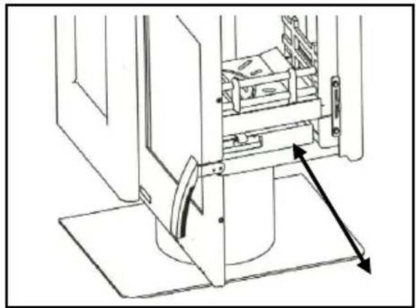
natural_image
Technical line drawing of a mechanical assembly with no visible text or symbolsBild 4
natural_image
Line drawing of a cabinet interior with an open door and internal compartments, showing a directional arrow indicating movement (no text or symbols present)Bild 5
text_image
Technical diagram of a mechanical assembly with numbered components and directional arrows indicating movement or force.Bild 7
Thank you for choosing our product!
By purchasing this product you receive guarantee for
• good quality originating from the usage of the finest and proven materials,
- operating security which is controlled according to German and European norms (Corresponds to the standard EN 13240)
- long life ensured by the robust structure.
In order to be able to use your new fireplace for a long time please read the following instructions manual. You will find all the necessary information in it and some additional advice.
PLEASE NOTE:
When ordering replacement parts, the Article No. and Serial No. shown on the identification plate must be quoted.
Contents
Foreword 18
Contents.... 18
SAFETY INSTRUCTIONS.... 19
- Usage 21
1.2 Installation 22
1.3 Putting out of operation.... 23
1.4 Heating instructions 23
1.5 Cleaning and maintenance 24
1.6 Potential problems and how to tackle them 26
- Placing 27
2.1 Prescriptions 27
2.2 Place of installation 27
2.3 Distances 27
2.4 Connection of the fireplace 28
- Technical specification .... 30
3.1 Dimensional drawings.... 30
3.2 Dimension 31
3.3 EC Declaration of Conformity 31
SAFETY INSTRUCTIONS
- The stoves are tested to EN 13240 (see identification plate).
- For installation and for flue gas connections, the requirements of the Fire Regulations (FeuVO in Germany) apply, as well as local building regulations such as the following technical standards DIN 18896, DIN 4705, EN 13384, DIN 18160, EN 1856-2 and EN 15287. In order for the stove to function correctly the chimney to which you want to connect the stove must be in good condition.
- Before first use and before connecting to the chimney, you must read the Instructions for Use carefully and inform the local authority responsible for approving heating systems.
- While installing the stove you are recommended to wear clean cotton gloves, in order to avoid leaving fingerprints which can be difficult to remove afterwards.
- In the interests both of clean air, and of the safe functioning of the stove, the fuel quantities listed in the Instructions for Use should never be exceeded, and the doors of the stove must be shut during use to avoid the risk of overheating, which can lead to damage to the stove. Damage due to this cause is not covered by the guarantee.
- The stove doors must remain shut at all times while the stove is in use.
- Permitted fuels are:
- Natural chopped firewood (up to 33 cm max. in length)
- Lignite (brown coal) briquettes (see permitted fuels in the Instructions for Use)
- Never use liquid fire starters. Use either special firelighters or wood shavings.
- Burning rubbish, fine chips, bark, coal slack, chips from planing, damp wood or wood treated with preservative, paper, cardboard or similar is not permitted.
- The first time the stove is heated there may be some smoke and an unpleasant smell. Make sure that the room is well ventilated (open windows and doors) and heat for at least an hour at the maximum nominal heat load. If the maximum temperature is not reached the first time the stove is heated, then there may be further unpleasant smells at a later date.
- All controls and settings must be used as indicated in the Instructions for Use. When the stove is hot, please handle only using the implements or protective gloves provided.
- If the stove is not working correctly, or if the chimney is not drawing properly, smoke may appear when the fire door is opened. It is very important to only open the fire door slowly, initially just a crack, then wait a few seconds before opening fully. In addition, before opening the fire door to top up the fuel, make sure that only glowing material is present: there must not be any visible flames.
- Do not place any flammable items in the warming drawer or on the surface of the stove.
- When in use, all surfaces and particularly the glass doors and handles and other controls can become very hot. Make children, young people, older people and animals aware of this danger, and keep them away from this source of heat when the stove is being used. Use the protective gloves or the implements provided. Children
and young people under 16 must not use the stove unless supervised by an adult who is responsible for them.
- Make sure that the ash pan is always fully pushed in, until it touches the back. Never remove ashes while still hot (fire risk).
- In spring and autumn the chimney may no longer draw correctly, so that gases produced by combustion are not completely removed. The fire chamber should then be filled with a small quantity of fuel, ideally with wood shavings, and lit under supervision, in order to stabilise the chimney draught. The grate must be clean.
- After each prolonged period of use for heating, have the stove checked by a professional. The flues and pipes for the evacuation of fumes must also be thoroughly cleaned.
- If repairs or replacements are necessary, please contact your supplier with the necessary article numbers and serial numbers in good time. Only original WAMSLER replacement parts may be used.
- Work such as installation, setup, commissioning and services, as well as repairs, must only be carried out by qualified personnel (heating system or space heating technicians). Intervention by non-qualified persons invalidates the warranty and guarantee.
- As the solid fuel oven/stove draws the air required for combustion from the surrounding room, you must ensure that sufficient air can be drawn in through non-sealed windows and outside doors. It can be assumed that is this is provided by a room volume of at least 4 m^3 per kW nominal heat capacity. If the volume is less than this, then air vents can be used to provide access to further air in other rooms (min. 150 cm^2 ).
- You must ensure that the correct safety distance is maintained from all flammable components and materials – to the side, rear and front. These distances can be found in the Instructions for Use or the identification plate.
- The fire chamber must not be modified.
- Connection to a chimney whose functional height is less than 4 m, or if multiple stoves are installed, 5 m, is not permitted. A maximum of two other fires can be connected to the chimney which is to be connected the stove.
- If the chimney catches fire immediately close all doors and openings and call the fire brigade. Do not attempt to extinguish the fire yourself. Afterwards have the chimney thoroughly checked out by a professional.
- Solid fuels naturally create soot, so it is always possible that the window glass will become dirty: this does not mean there is a malfunction.
1. Usage
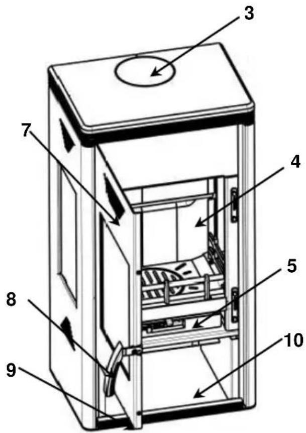
1.1 Structure of the equipment
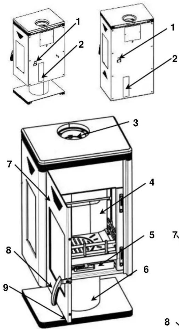
- Fuel selector
- Model plate on the rear wall
- Smoke tube end
- Furnace chamber walling
- Ash bin
- Plinth
- Furnace chamber door
- Door knob
- Primary air regulator
- Fuel storage
text_image
Technical diagram of a multi-compartment refrigerator with numbered parts labeled 3 through 101.2 Installation
Fuels
Low smoke, trouble-free operation of the stove and a supply of heat at the nominal level with a chimney draught of 12 Pa are only guaranteed when you use the following fuels and no others.
Only use natural, dry chopped firewood with a remaining humidity of max. 20%, and lignite (brown coal) briquettes.
| Types of fuels | Heating value appr. kJ/kg |
| Hard wood | 19.500 |
| Soft wood | 15.900 |
| Brown-coal | 11.500 |
With the primary air damper, do you adjust the rated output.
There may be engaged in only the settings and fuel quantities are given that correspond to your licensed or purchased device.
Adjustment:
| Fuel | Setting of the primary air regulator | Setting of the fuel selector | Burning time | |
| 8 kW | ||||
| Warning up, kindling | III | H | - | |
| Wood | Nominal heating performance | II | H | ca. 0,75 h |
| Brown-coal | Nominal heating performance | III | K | ca. 1 h |
| Putting out of working order | I | K | - | |
Table 2
Filling quantities 8 kW
-Split billet: max. length: 33 cm, max. 3 billets per filling, appr. 1,8 kg
-Lignite briquette: max. 2,4 kg
IT IS NOT ALLOWED to burn waste, fine chipping, bark, wood handled with preventive chemicals, furthermore paper and cardboard. For kindling please use wood scrapings or grill starter but never use liquid auxiliaries!
The first kindling
- At the first fire set-up could be a little smoke, but is not dangerous, normal! In this time, please ventilate the room carefully!
Warning! Upon the first kindling, smoke and unpleasant smell may be generated. Always ensure the proper ventilation of the room (by opening windows and doors), and heat the fireplace at maximum rated heating performance. If with the first heating the maximum temperature is not reached, the above-mentioned effects may as well arise later on.
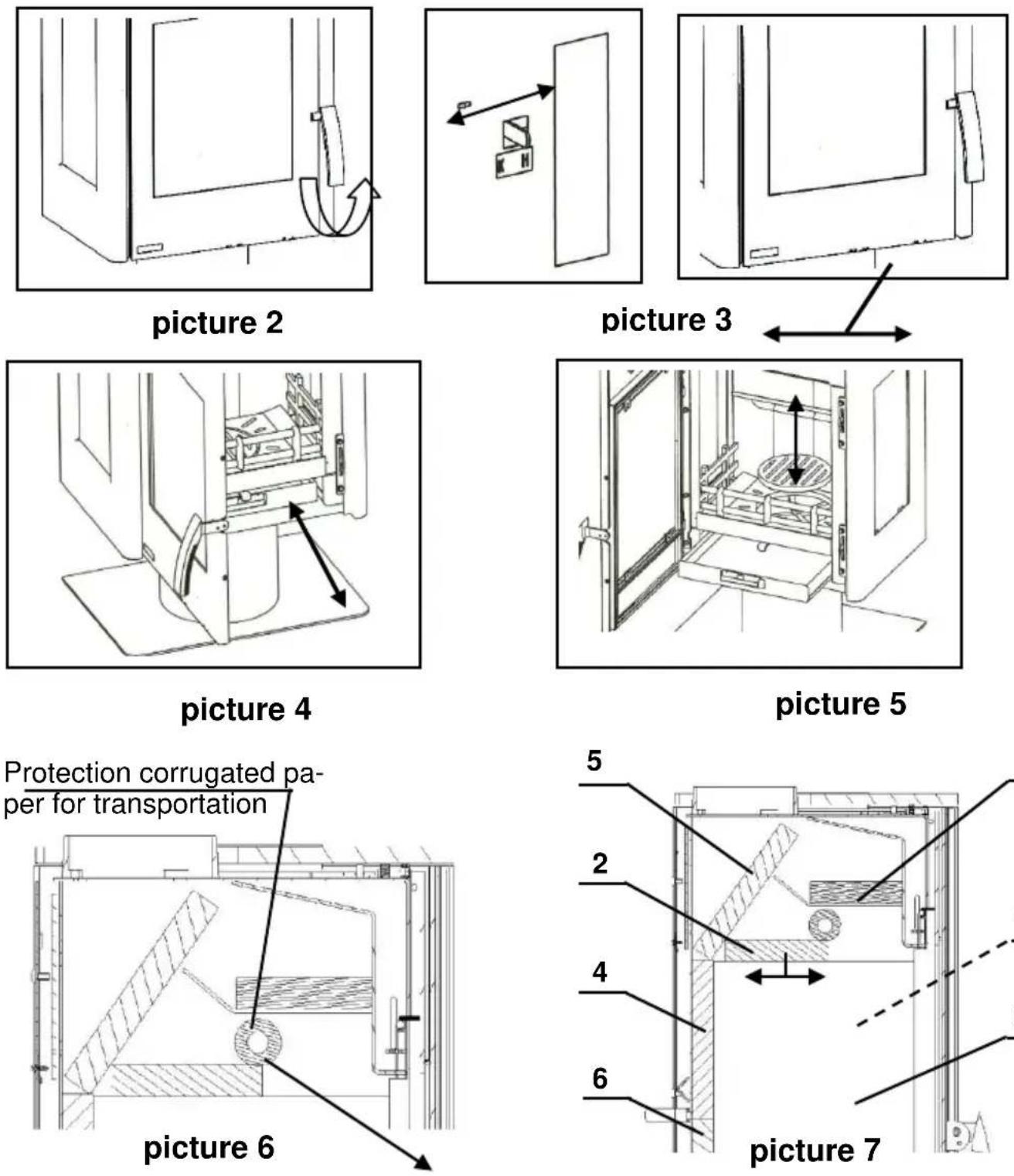
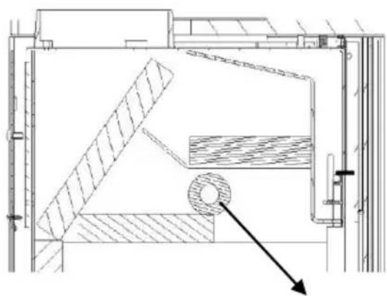
- Before installation pull out the delivery securer off the refractory brick through the furnace chamber (picture no. 6).
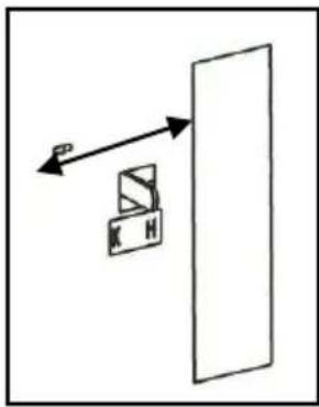
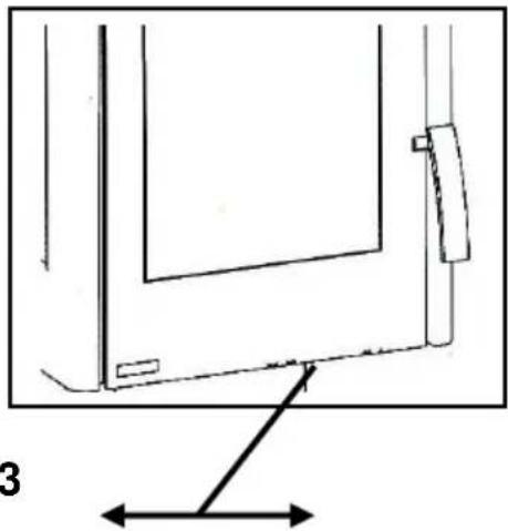
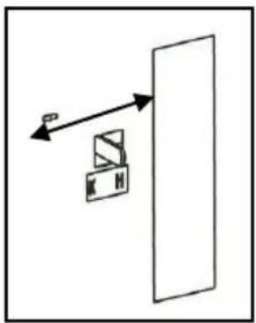
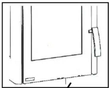
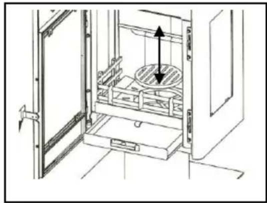
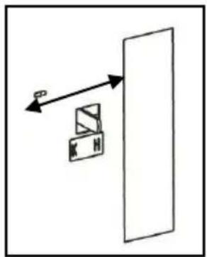
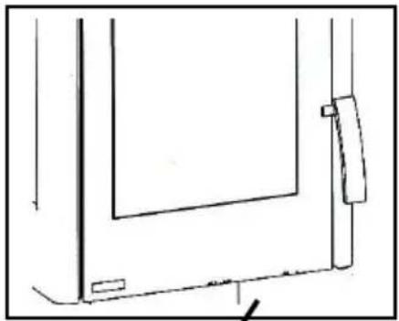
Open the door by raising the handle (Picture 2). If the equipment is hot, you can use insulated gloves. Adjust the primary air regulator and the fuel switch (Picture 3) according to the Table 2. Put coal lighter or wood wool onto the fire grate, followed by wood chips. First insert small pieces of wood, and then larger ones, light them and close the door again. When the wood burns quickly, and leaves sufficient glowing embers, put additional fuel on the fire. Thereafter, adjust the primary air regulator and the fuel switch according to the Table 2 („Adjustment of the burning air”).
The first kindling should be performed “finely” with little fuel only, so that the parts of the fireplace are adapted to heat. During the first kindling, the generation of smell is normal and absolutely undangerous.
1.3 Putting out of operation
- Let the glowing ember burn to ashes and the fire-place get cold.
• Empty the furnace chamber and the ash bin. - Close the doors, and shut off the primary air regulator (position I) and the fuel switch (position K).
1.4 Heating instructions
The fireplace should be operated only with closed furnace chamber door. Fireplaces belonging to type 1 have self-locking furnace chamber doors. These doors may be opened only for kindling, loading or when cleaning the furnace chamber (otherwise draught problems may occur with other equipment connected to the same chimney).
Warning!
When opening the furnace chamber door, any incorrect handling or insufficient draught may induce smoke. Always ensure that the furnace chamber door may be opened only slowly, first just to a small extent, and then fully after a few seconds. In addition, if you intend to put additional fuel into the fire, before the opening of the door only there may be only ember bed in the burning space, i.e. no flames may be visible.
Led into the burning space in correspondence with the existing conditions, the secondary air provides for the follow-up burning of the combustible components of in the burning space. This in fact means smoke and soot-poor burning, which contributes to the protection of the environment. If you wish to commission the fireplace in a transitional period, please, please first examine the chimney draught, as it can be especially weak at high external temperatures. Towards this end, hold a burning
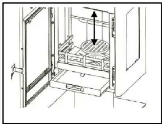
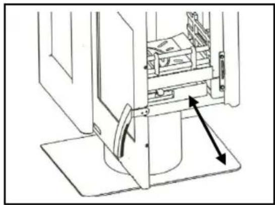
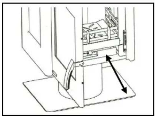
match in the slightly opened feeding door. If the flame is not drawn significantly by the draught, then a so-called starting fire is to be set first. Towards this end, burn wood chips/wool in the fireplace or the cleaning hole of the chimney. The fire grate is to be cleaned before every kindling to ensure the proper inflow of air for burning. The ashtray is to be emptied regularly (Figure 4). Should the equipment be extremely hot, use the gloves provided. Please, be careful not to dispose glowing materials into the waste bin.
Ensure that the ashtray should be fully pushed into the equipment.
Warning! In order to keep the air clean and safeguard the fireplace, do not exceed the specified maximum fuel quantity, otherwise overheating may occur, which potentially damage the equipment. Such damage is not covered with any guarantee. Only a single layer of fuel is allowable to be prepared in the fireplace. Try to reach lower heating performance only by decreasing the quantity of fuel, and not by cutting the primary air supply.
1.5 Cleaning and maintenance
After the heating season, it is recommended to clean the fireplace and the flue gas pipes carefully. Any dropping heating performance is almost always the consequence of the strong contamination of the flues. For cleaning, the baffle plate (Picture7) is to be pulled forward. This way, the flues can be cleaned from the inside or – after removing the flue gas pipe – from above. After cleaning, the baffle plate (Picture 7) is be pushed back fully again.
Warning!
Following every heating season you are advised to examine the fireplace thoroughly. If any repair or reconditioning is needed, please, contact your local dealer in a timely manner, and specify the model number and serial number of your equipment (as seen on the model plate). External surfaces may be maintained only after the fireplace cooled down, and following the first commissioning. Use cold water for cleaning, or soap, washing ingredient in extraordinary cases, then wipe it dry. Before its first use, clean the ROBAX inspection glass with a wet and clean cloth, and then put a few drops of glass—ceramics cleaner onto both sides of the glass, and spread them with the use of kitchen paper tissues. It provides an invisible film on the valuable surface of the Robax glass. This film helps to keep the glass clean, and facilitates regular cleaning operations. ROBAX S for slightly contaminated surfaces – a commercially available glass surface cleaning agent – may as well be used for the cleaning of the medium or strongly contaminated glass surfaces of the fireplace. Towards this end, spray small quantities of the agent to the cold surfaces, spread it, and wash it down with a wet cloth, followed by drying with a clean, soft cloth. In case there are sticky fuel deposits on these surfaces, first scale simply them with a ceramic-plate scraper held in flat angle, and then clean the surfaces as described above.
Cleaning of the ceramic surfaces dirt and grease are to be removed with soap and water.
Cleaning of the soapstone: the soapstone is a natural stone, therefore minor colour differences may occur; as it is normal, they may not serve as a basis for quality complaints! To clean the soapstone from dirt and fat with water and soap, as well as small scratches, use sand paper (grain size 240).
Warning: Under no circumstances you may use sponge, scouring, aggressive or scratching cleaning agents! If the grate is blocked so that the equipment cannot serve the intended function, the grate is to be removed for cleaning.
1.6 Potential problems and how to tackle them
| Kind of operating problem | Possible reasons | Solution |
| Odour formation | Curing of the applied preventive lacquer.Steaming oil remains. | Operate the fire-place on a low heating level according to the instructions manual for a few hours. Then heat up for maximal performance for a few hours. |
| Too little heating performance | We chose too little performanceChimney draught is slight | Have the heating requirement of the room examined by an expertChimney draught shall be at least 12 Pa, max. for a short time 18 Pa.Check the tightness of your chimney and also that the doors of other fire-places leading to the same chimney are closed and sealed properly. Make sure that the chimney-cleaning joints are sealed properly. |
| Too long and leaky smoke tube | All the smoke tube joints must be well sealed and fireproof-isolated | |
| Leakage at the door glass | Check the sealing, close the door properly. May have to have the tightening flap renewed. | |
| Usage of wet wood. | Use well dried wood only. |
Actions to be in chimney fire
Chimney fire may occur upon the improper cleaning of the chimney, the use of inappropriate fuels (e.g. excessively wet wood) or the inadequate setting of the burning air. In such cases, close the burning air at the fire, and call the fire service.
Never try to extinguish the fire with water!
2. Placing
2.1 Prescriptions
For installation and for connection of flue, the requirements of the Fire Regulations (FeuVO in Germany) apply, as well as local building regulations such as the following technical standards DIN 18896, DIN 4705, EN 13384, DIN 18160, EN 1856-2 and EN 15287. In order for the stove to function correctly the chimney to which you want to connect the stove must be in good condition.
2.2 Place of installation
The stove draws the air required for burning from the surrounding room. You must ensure that sufficient air can be drawn in through non-sealed windows and outside doors. In addition you must ensure that a room volume/heat capacity ratio of at least 4 m^3 per kW nominal heat capacity is available. If the volume is less than this, then air vents can be used to provide access to further air supply in other rooms (connecting vents min. 150 cm^2 ).
2.3 Distances
All the combustible materials, furniture or e.g. decoration materials that are in the close environment of the fireplace should be protected from the heat.
Furnishing in the radiation area
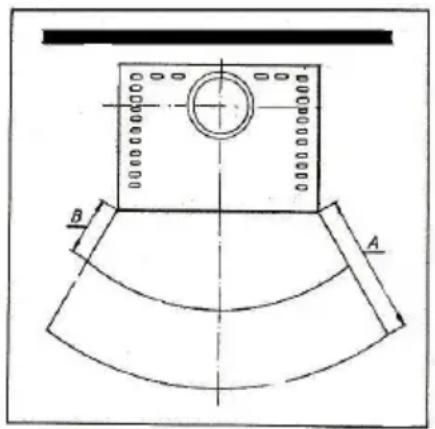
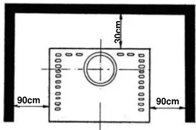
Keep a minimal distance of 90 cm (A) between the front edge of the fireplace and the combustible equipment, furniture or e.g. decoration materials in the building. The security distance can be reduced to 50 cm (B) if a heat shield is placed in front of the object to be protected (see example in Picture 8).
Furnishing beyond the radiation area
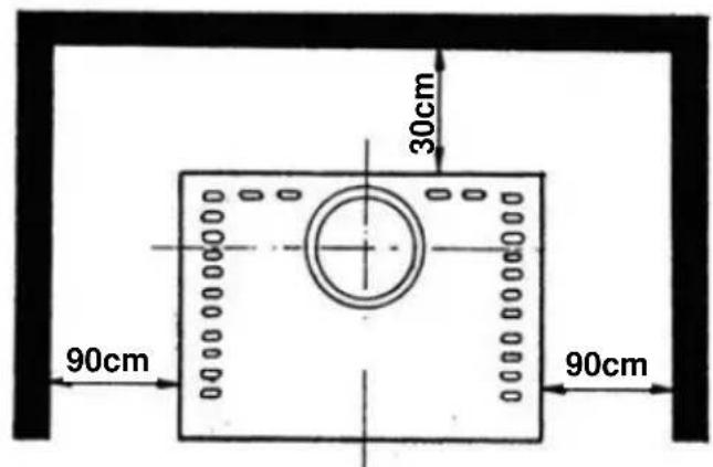
The walls beside and behind the fireplace may not be made of combustible materials, and they cannot be covered with such materials if the distance on the sides is under 90 cm, or 30 cm on the rear side. Similarly, the distance to wooden and plastic furniture on the sides should be at least 90 cm (see Picture 9).
text_image
B Apicture 8
text_image
30cm 90cm 90cmpicture 9
Floor in front of and under the fireplace
Floors made from combustible materials, such as carpets, parquet floors or cork is to be protected by a shield of non-combustible material – for example ceramics, stone, glass or steel – placed under the fireplace so that it should reach out to 50 cm in front and 30 cm besides.
2.4 Connection of the fireplace
The connection for attaching to the chimney must be able to withstand at least 400^ C.
PLEASE NOTE:
Before connecting the stove the local authority responsible for approving heating systems must be consulted!
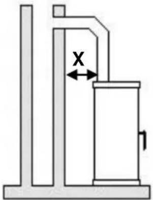
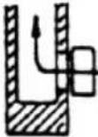
Connection pieces must be firmly connected to the stove and to each other and must not leak. They must not project into the open diameter of the chimney. The connection piece between the stove and the chimney must have the same diameter as the pipe socket on the stove. Horizontal connection pieces of over 0.5 m must rise towards the chimney at an angle of 10 degrees. Any pipes which are not heat insulated or vertical must not be longer than 1 metre.
The requirements of the Fire Regulations (FeuVO) apply, as well as local building regulations such as for the chimney standards DIN 18896, DIN 4705, EN 13384, DIN 18160 and EN 15287. Connection pieces must be tested to EN 1856-2. Measurement X (distance from flammable construction and other materials) must be as defined by the manufacturer of the connection piece.
text_image
XPLEASE NOTE:
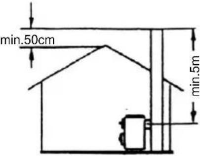
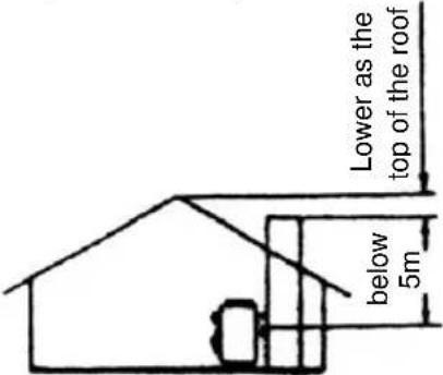
Fitting to a chimney with a functional height of less than 4 m, or if several stoves are being fitted, less than 5 m, is not permitted.
(See: Data for chimney calculations / Chapter 3.) A maximum of two other fires can be connected to the chimney to be connected to the stove.
For safety reasons it is not permitted to use a steam extractor hood to remove air when the stove is producing heat.
text_image
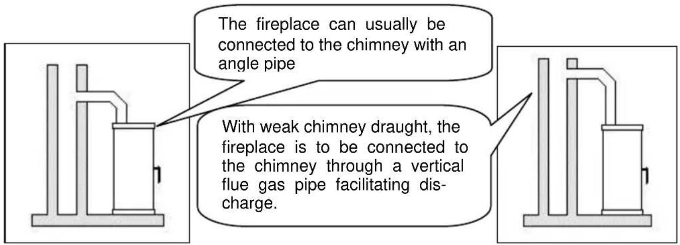
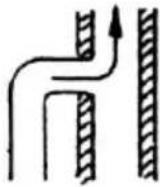
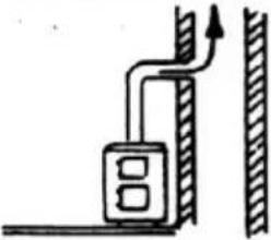
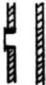
The fireplace can usually be connected to the chimney with an angle pipe With weak chimney draught, the fireplace is to be connected to the chimney through a vertical flue gas pipe facilitating discharge.| Correct | Incorrect | |
 |  | |
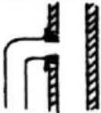
 | 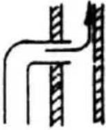 | Tightening cross section of the chimney because the smoke tube is pushed into the chimney too much |
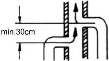 | 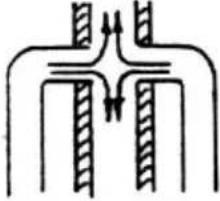 | Obstruction, because the smoke tubes are led as facing each other |
 | [Faulty d because fire-plac door (nc use) is c 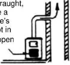 ] ] | |
 | [Fals an c 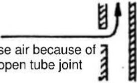 ] ] | |
 | [Fals beca leak 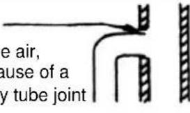 ] ] | |
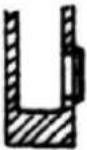 |  False air, because a open fire-place door False air, because a open fire-place door | |
3. Technical specification
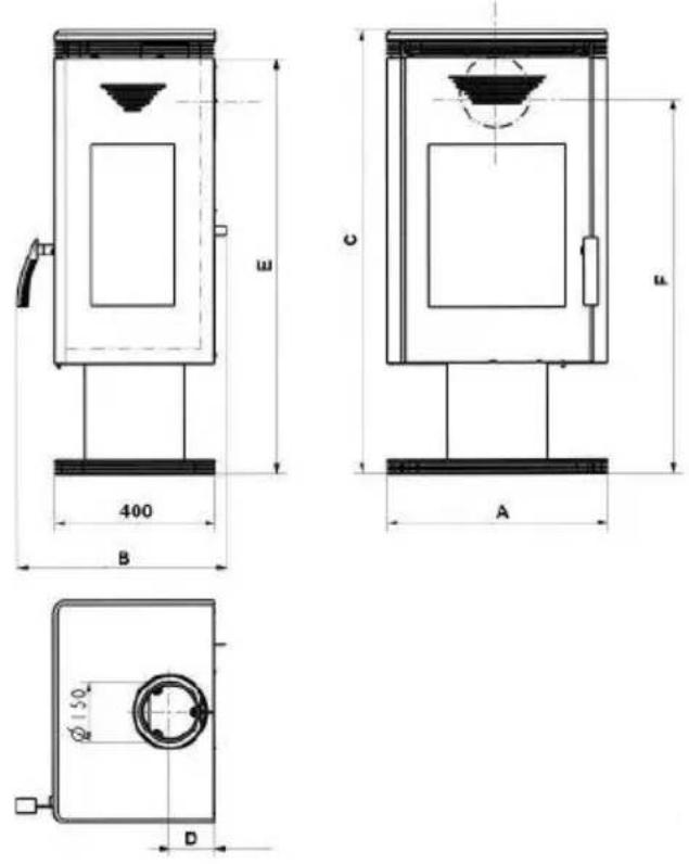
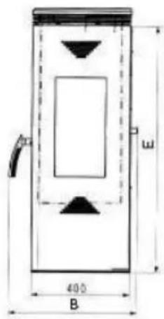
3.1 Dimensional drawings
TYP10188 TRION/VISTA/SAN FILOU
TYP10188 TRION-H/VIOLA
text_image
400 B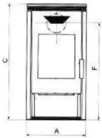
text_image
C A L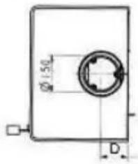
text_image
Ø150 D| Type | TYP10188 |
| Nominal performance | 8 kW |
| Heating capacity (m3) | 182 |
| -under favourable | 105 |
| -less favourable | 71 |
| -not favourable heating circumstances according to 18893/TAB2 DIN standard | |
| Flue gas values: fuel: | wood / brown coal |
| Flue gas stream: | 8,5 g/s |
| Flue gas temperature: | 335°C |
| Min. blast pressure at performance: | 12 Pa |
| CO (relating to 13% O2) | ≤ 40 mg/m3 |
| dust (relating to 13% O2) | 1121 / 1051 mg/Nm3 |
| efficiency | ≥ 75 % |
All information provided by the exhaust gas values are based on the EN 13240 under stationary laboratory conditions
3.2 Dimension
| Art. No. | A(mm) | B(mm) | C(mm) | D(mm) | E(mm) | F(mm) | Weight* netto |
| W20001018810 | 550 | 520 | 1099 | 110 | 1028 | 926 | 120 |
| W20001018850 | 550 | 520 | 1074 | 110 | 1028 | 926 | 105 |
| G001018820 / 30 / 40 | 580 | 520 | 1099 | 110 | 1028 | 926 | 116 |
| W20001018815 | 550 | 520 | 1070 | 110 | 999 | 896 | 121 |
| G001018860 | 580 | 520 | 1050 | 110 | 999 | 896 | 132 |
* Basic equipment with ceramics
The specified dimensions and weights are approximate values, and thus have only informative purposes. We reserve the right to modify the designs as required in terms of technology or quality!
3.3 EC Declaration of Conformity

EC-Declaration of Conformity
Manufacturer:
Product description: Solid fuel stove
Model no: TYP 101 88
The products listed above conform to the requirements of the following European Directive:
89/106/EC: Construction Products Directive
This is attested by test reports No. FSPS-Wa 1517-EN and FSPS-Wa 1916-EN of 04.09.2006 and 07.01.2010 from the state-accredited test centre RWE Power AG Frechen (notified body number 1427), tested under EN 13240.
Munich, 19.09.2011
K.D. Knabel A. Freund
text_image
iV Gaul AManaging Director Technical Director
This declaration certifies conformity to he above-named Directives but does not provide any guarantee of product characteristics. The safety notices in the product documentation supplied must be adhered to. This declaration is no longer valid if the equipment is modified by a third party.
We reserve the right to make changes which relate to technical advances and / or to an improvement in quality. We accept no liability for printing errors and changes which occur after printing.
Préambule
Cher Client,
2.3 Distances minimum 45
natural_image
Simple line drawing of a door with an arrow indicating clockwise motion (no text or symbols)fig. 2
natural_image
Simple line diagram showing a device with an arrow pointing to a vertical panel, no text or symbols present.fig. 3
natural_image
Simple line drawing of a door frame with handle and base, no text or symbols present
natural_image
Technical line drawing of a mechanical assembly with no visible text or symbolsfig. 4
natural_image
Technical line drawing of a cabinet interior with an open door and internal compartments (no text or symbols)fig. 5
natural_image
Architectural cross-section diagram of a building interior with structural elements and a circular component (no text or labels)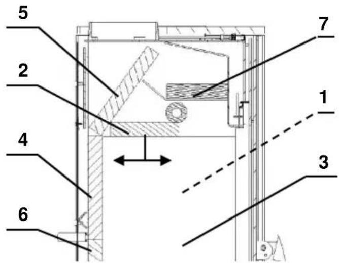
text_image
5 2 4 6 7 1 3fig. 6
fig. 7
1.6 Anomalies
2.3 Distances minimum
text_image
Technical diagram showing two views of a device with labeled components and directional arrows indicating movement or assembly.text_image
Technical diagram of a mechanical device with numbered components for identification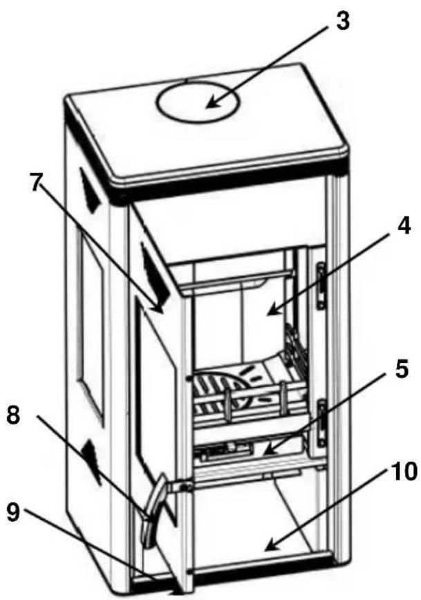
text_image
Technical diagram of a multi-compartment refrigerator with numbered parts and directional arrows indicating internal components.1.2 Accensione
Combustibili
natural_image
Simple line drawing of a door with an arrow indicating clockwise motion (no text or symbols)Fig. 2
natural_image
Simple line drawing of a door with an arrow indicating direction and a small object inside (no text or symbols)Fig. 3
natural_image
Simple line drawing of a door frame with handle and angle marker (no text or symbols)
natural_image
Technical line drawing of a mechanical assembly with no visible text or symbolsFig. 4

natural_image
Technical line drawing of a door with an open shelf and internal compartments, showing no text or symbolsFig. 5
natural_image
Technical line drawing of a mechanical assembly with hatched areas and a circular component, no visible text or symbolstext_image
Technical diagram of a mechanical assembly with numbered components and directional arrows indicating movement or force.Fig. 7
text_image
Technical diagram of a mechanical component with labeled sections A and B, showing cross-sectional views and centerlines.Fig. 8
text_image
30cm 90cm 90cmFig. 9
text_image
d ≥ 5m d ≤ 5m 0,50m 0,50m