
CTS801II - Printer CITIZEN - Free user manual and instructions
Find the device manual for free CTS801II CITIZEN in PDF.
| Product Type | Thermal line printer |
| Brand | Citizen |
| Model | CTS801II |
| Dimensions (built-in power supply type) | 145 x 192 x 148 mm |
| Dimensions (AC adapter type) | 145 x 192 x 120 mm |
| Weight (built-in power supply type) | Approx. 2 kg |
| Weight (AC adapter type) | Approx. 1.6 kg |
| Power supply | DC 24 V ±5%; AC adapter 100-240 V, 50/60 Hz |
| Power consumption | Approx. 45 W (printing), 3 W (standby) |
| Maximum print speed | 300 mm/s |
| Resolution | 203 dpi (8 x 8 dots/mm) |
| Print width | Up to 80 mm (depending on paper) |
| Available interfaces | USB, RS-232C Serial, Parallel, Ethernet, Bluetooth, WiFi |
| Display | LCD 128 x 32 dots, white/red LED backlight |
| Main functions | Thermal printing, automatic and manual cutter, 1D/2D barcodes, 16-level grayscale, user memory 384 KB |
| Maintenance and cleaning | Clean the print head and platen regularly with an alcohol-moistened cotton swab |
| Safety | Do not expose to moisture, shock, or disassemble; unplug before cleaning |
| Spare parts and repairability | Contact an authorized Citizen dealer for any repairs; do not attempt to repair yourself |
| Operating temperature | 5 to 45°C, 10 to 90% RH (non-condensing) |
| Storage temperature | -20 to 60°C, 10 to 90% RH (non-condensing) |
| Print head reliability | 150 km or 200 million pulses |
| Cutter life | 2 million cuts |
Frequently Asked Questions - CTS801II CITIZEN
User questions about CTS801II CITIZEN
0 question about this device. Answer the ones you know or ask your own.
Ask a new question about this device
Download the instructions for your Printer in PDF format for free! Find your manual CTS801II - CITIZEN and take your electronic device back in hand. On this page are published all the documents necessary for the use of your device. CTS801II by CITIZEN.
USER MANUAL CTS801II CITIZEN
LINE THERMAL PRINTER
MODEL CT-S801 Type II
User's Manual
Mode d'emploi
Benutzerhandbuch
Manuale dell'utente
Manual de Usuario
natural_image
Line drawing of a mechanical device with ports and casing (no text or symbols)If you want to dispose of this product, do not mix it with general household waste. There is a separate collection systems for used electronics products in accordance with legislation under the WEEE Directive (Directive 2002/96/EC) and is effective only within European Union.
Ge
Declaration of Conformity
This printer conforms to the following Standards:
The Low Voltage Directive 2006/95/EC, the EMC Directive 2004/108/EC, the RoHS Directive 2011/65/EU, and the WEEE Directive 2002/96/EC.
LVD : EN60950-1
EMC: EN55022 Class A
EN61000-3-2
EN61000-3-3
EN55024
This declaration applies only to the 230-V model.
IMPORTANT: This equipment generates, uses, and can radiate radio frequency energy and if not installed and used in accordance with the instruction manual, may cause interference to radio communications. It has been tested and found to comply with the limits for a Class A computing device pursuant to Subpart J of Part 15 of FCC Rules, which are designed to provide reasonable protection against such interference when operated in a commercial environment. Operation of this equipment in a residential area is likely to cause interference, in which case the user at his own expense will be required to take whatever measures may be necessary to correct the interference.
CAUTION: Use shielded cable for this equipment.
Sicherheitshinweis
This Class A Information Technology Equipment (ITE) complies with Canadian CAN ICES-3(A)/NMB-3(A).
This Information Technology Equipment (ITE) does not exceed the Class A limits for radio noise emissions from digital apparatus set out in the Radio Interference Regulations of the Canadian Department of Communications.
- Before using this product, be sure to read through this manual. After having read this manual, keep it in a safe, readily accessible place for future reference.
- The information contained herein is subject to change without prior notice.
● Reproduction or transfer of part or all of this document in any means is prohibited without permission from Citizen Systems. - Note that Citizen Systems is not responsible for any operation results regardless of omissions, errors, or misprints in this manual.
- Note that Citizen Systems is not responsible for any trouble caused as a result of using options or consumables that are not specified in this manual.
- Except explained elsewhere in this manual, do not attempt to service, disassemble, or repair this product.
- Note that Citizen Systems is not responsible for any damage attributable to incorrect operation/handling or improper operating environments that are not specified in this manual.
- Data is basically for temporary use and not stored for an extended period of time or permanently. Please note that Citizen Systems is not responsible for damage or lost profit resulting from the loss of data caused by accidents, repairs, tests or other occurrences.
- If you find omissions, errors, or have questions, please contact your Citizen Systems dealer.
- If you find any pages missing or out of order, contact your Citizen Systems dealer for a replacement.
"Made for iPod," "Made for iPhone," and "Made for iPad" mean that an electronic accessory has been designed to connect specifically to iPod, iPhone, or iPad, respectively, and has been certified by the developer to meet Apple performance standards. Apple is not responsible for the operation of this device or its compliance with safety and regulatory standards.
Please note that the use of this accessory with iPod, iPhone or iPad may affect wireless performance.
- iPad, iPhone and iPod touch are trademarks of Apple Inc., registered in the U.S. and other countries. iPad Air and iPad mini are trademarks of Apple Inc.
● EPSON and ESC/POS are registered trademarks of Seiko Epson Corporation. - QR Code is a registered trademark of DENSO WAVE INCORPORATED.
- Ethernet is a registered trademark of Fuji Xerox Corporation.
- Bluetooth® is a registered trademark of Bluetooth-SIG Inc.
● CITIZEN is a registered trademark of Citizen Watch Co., Ltd. Japan
● All other trademarks are the property of their respective owners. - Citizen Systems use these trademarks in accordance with the license of relevant owners.
SAFETY PRECAUTIONS...WHICH SHOULD BE STRICTLY OBSERVED
Before using this product for the first time, carefully read these SAFETY PRECAUTIONS. Improper handling may result in accidents (fire, electric shock or injury).
In order to prevent injury to operators, third parties, or damage to property, special warning symbols are used in the User's Manual to indicate important items to be strictly observed.
- After having read this Manual, keep it in a safe, readily accessible place for future reference.
- Some of the descriptions contained in this manual may not be relevant to some printer models.
The following describes the degree of hazard and damage that could occur if the printer is improperly operated by ignoring the instructions indicated by the warning symbols.

WARNING
Neglecting precautions indicated by this symbol may result in fatal or serious injury.

CAUTION
Neglecting precautions indicated by this symbol may result in injury or damage to property.

This symbol is used to alert your attention to important items.

This symbol is used to alert you to the danger of electric shock or electrostatic damage.

This symbol denotes a request to unplug the printer from the wall outlet.

This symbol is used to indicate that the power supply must be grounded.

This symbol is used to indicate useful information, such as procedures, instructions or the like.

This symbol is used to indicate prohibited actions.
PRECAUTIONS ON PRINTER INSTALLATION

WARNING
■ Do not use or store this product in a place where it will be exposed to:
* Flames or moist air.
* Direct sunlight.
* Hot airflow or radiation from a heating device.
* Salty air or corrosive gases.
* Ill-ventilated atmosphere.
* Chemical reactions in a laboratory.
* Airborne oil, steel particles, or dust.
* Static electricity or strong magnetic fields.
- Neglecting these warnings may result in printer failure, overheating, emission of smoke, fire, or electric shock.


■ Do not drop any foreign object nor spill liquid into the printer. Do not place any object on the printer either.
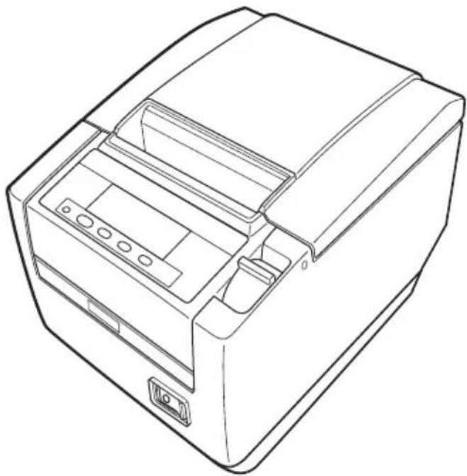
■ Do not drop any metallic object such as paper clips, pins or screws into the printer.
■ Do not place a flower vase, pot, or anything containing water on the printer.
■ Do not spill coffee, soft drinks, or any other liquid into the printer.
■ Do not spray insecticide or any other chemical liquid over the printer.
- Dropping a metallic foreign object into the printer, may cause printer failure, fire, or electric shock. Should it occur, immediately turn the printer off, unplug it from the supply outlet, and call your local Citizen Systems dealer.


Do not handle the printer in the following ways:
■ Do not subject the printer to strong impacts or hard jolts (e.g., being stepped on, dropped or struck).
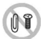
■ Never attempt to disassemble or modify the printer.
- Neglecting to handle properly may result in printer failure, overheating, emission of smoke, fire, or electric shock.

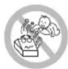
■ Install, use, or store the printer out of the reach of children.
- Electric appliances could cause an unexpected injury or accident if they are handled or used improperly.
- Keep the power cord and signal cables out of the reach of children. Also children should not be allowed to gain access to any internal part of the printer.
- The plastic bag the printer came in must be disposed of properly or kept away from children. Wearing it over the head may lead to suffocation.

CAUTION
Do not use the printer under the following conditions.
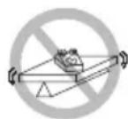
■ Avoid locations subject to vibration or instability.
■ Avoid locations where the printer is not level.
- The printer may fall and cause an injury.
- The quality of printing may deteriorate.
- Do not obstruct the printer's air vents.
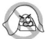
■ Do not place anything on the printer.
■ Do not cover or wrap the printer in cloth or blankets.
- Doing so could cause heat to build up and deform the case or start a fire.
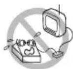
■ Avoid using the printer near a radio or TV set or from supplying it from the same electric outlet as these appliances.
■ Avoid using the printer interconnected with a cable or cord that has no protection against noise. (For interconnections, use shielded or a twisted pair of cables and ferrite cores, or other anti-noise devices.)
■ Avoid using the printer with a device that is a strong source of noise.
- The printer may have an adverse effect on nearby radio or TV transmissions. There may also be cases when nearby electrical appliances adversely influence the printer, causing data errors or malfunction.
■ Installed in any orientation other than those specified.
- Malfunction, failure, or electric shock may result.
■ Connect the printer to a ground.
• Electric leakage may cause an electric shock.
- Do not connect the printer's ground to any of the following:
* Gas piping
• A gas explosion could result.
* Telephone line ground
* Lightning rod
- If lightning strikes a large surge of current may cause fire or shock.
* Water pipes
- Plastic water pipes should not be used for grounding. (Those approved by a Waterworks Department may be used.)
■ Before connecting or disconnecting the grounding lead to or from the printer, always unplug it from the electric outlet.


PRECAUTIONS IN HANDLING THE PRINTER

WARNING
Please observe the following precautions for power source and power cord:
■ Do not plug or unplug the power cord with a wet hand.
■ Use the printer only at the specified supply voltage and frequency.
■ Use only the specified AC adapter with the printer.
- Check to make sure that the supply outlet from which the printer is powered has a sufficient capacity.
■ Do not supply the printer from a power strip or current tap shared with other appliances.
■ Do not plug the power cord into an electric outlet with dust or debris left on the plug.
■ Do not use a deformed or damaged power cord.
■ Do not move the printer while its power is on.
- Neglecting to handle it properly may result in printer failure, emission of smoke, fire, or electric shock.
- An overload may cause the power cord to overheat, catch fire, or the circuit breaker to trip.
■ Do not allow anything to rest on the power cord. Do not place the printer where the power cord may be stepped on.
■ Do not use or carry the printer with its power cord bent, twisted, or pulled.
■ Do not attempt to modify the power cord unnecessarily.
■ Do not place the power cord near any heating device.
- Neglecting these cautions may cause wires or insulation to break, which could result in electric leakage, electric shock, or printer failure. If the power cord sustains damage, contact your Citizen Systems dealer.
■ Do not leave things around the electric outlet.
■ Supply power to the printer from a convenient electric outlet, readily accessible in an emergency.
- Pull the plug to immediately shut it down in an emergency.
■ Insert the power plug fully into the outlet.
■ If the printer will not be used for a long time, disconnect it from its electric outlet.
■ Hold the plug and connector when plugging or unplugging the power cord or signal cable after turning off the printer and the appliance connected to it.


CAUTION
Caution label is attached in the position shown in the following figure. Carefully read the handling precautions before using the printer.
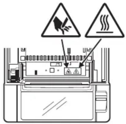
THIS LABEL INDICATES THE RISK OF BURNS DUE TO THE HIGH TEMPERATURE OF THE PRINT HEAD AND A RISK OF BEING CUT BY THE MANUAL AND AUTO CUTTERS WHILE THE PAPER COVER IS OPEN.
■ Do not transport this printer with the paper roll inside.
- Printer failure or damage may occur.
To prevent possible malfunction or failure observe the following.
■ Do not open the paper cover during printing.
■ Avoid operating the printer without paper properly loaded.
■ Avoid the use of paper not complying with specifications.
- May result in poor print quality.
■ Avoid using torn pieces of paper or paper spliced with plastic adhesive tape.
■ Avoid forcibly pulling already loaded paper by hand.
■ Avoid using a sharp pointed device to operate panel buttons.

■ Be sure to firmly insert the cable plugs into their mating sockets.
- A cross connection may damage the printer's internal electronics or the host system's hardware.
■ Only use the printer with devices that have designated solenoid specifications for the cash drawer interface connector.
- Neglecting this caution may result in malfunction or failure.

CAUTION
To prevent injury and printer failures from worsening, observe the following:
■ While the paper cover is open, be careful to not touch the manual cutter that is in the paper eject slot.
■ Do not touch the printing surface of the thermal head.
■ Do not touch any of the moving parts (e.g., paper cutter, gears, active electric parts) while the printer is working.
In case of trouble do not attempt to repair the printer. Ask Citizen Systems service for repair.
■ Be careful that the covers do not pinch your hands or fingers.
■ Be careful of the sharp edges on the printer. Do not allow them to injure you or damage property.
- May result in electric shock, burn, or injury.
If the printer emits smoke, an odd smell, or unusual noise while printing, immediately abort the current print session and unplug the printer from the electric outlet.


DAILY MAINTENANCE
Observe the following precautions for daily maintenance.
■ When cleaning the printer, always turn it off and unplug it from the electric outlet.
■ Use a soft, dry cloth for cleaning the surface of the printer case.
For severe stains, use a soft cloth slightly dampened with water.
Never use organic cleaning solvent such as alcohol, paint thinner, trichloroethylene, benzene, or ketone. Never use a chemically processed cleaning cloth.
■ To remove paper dust, use a soft brush.


CAUTION
- The thermal head is at a dangerously high temperature immediately after printing. Allow it to cool off before starting maintenance work.
Visit the following site to get documentation, drivers, utilities, and other information.
http://www.citizen-systems.co.jp/english/support/index.html
THE TABLE OF CONTENTS
1. GENERAL OUTLINE....9
1.1 Features....9
1.2 Unpacking.... 10
1.3 Model Classification 10
1.4 Basic Specifications.... 11
2. EXPLANATION OF PRINTER PARTS ......13
2.1 Printer Appearance.... 13
2.2 Inside the Paper Cover 16
2.3 Other Built-in Functions.... 18
3. SETUP......20
3.1 Connecting the AC Power Cord 20
3.2 Connecting Interface Cables 21
3.3 Bluetooth Interface Board 23
3.4 Ethernet (LAN) Interface Board 25
3.5 Wireless LAN Interface Board 28
3.6 Connecting the Cash Drawer 32
3.7 Precautions for Installing the Printer 34
3.8 Partition for Paper Roll 35
3.9 Setting the DIP Switch on the Serial Interface Board.... 36
3.10 Adjusting the Paper Near-end Sensor 37
3.11 Loading Paper 38
3.12 Calibrating the Paper Sensor 39
3.13 Selecting a Paper Type 42
3.14 Attaching the Power Switch Cover 43
3.15 Attaching the Interface Cover 43
3.16 Removing the Interface Cover 44
3.17 Installing a Driver 44
3.18 Precautions for Creating Applications and Practical Operations 45
4. MAINTENANCE AND TROUBLESHOOTING......46
4.1 Periodic Cleaning.... 46
4.2 Clearing a Cutter Lock (1) 47
4.3 Clearing a Cutter Lock (2) 48
4.4 Function Test Mode 49
4.5 Key Lock Function 51
4.6 Hexadecimal Dump Printing 52
4.7 Error Messages 53
4.8 Paper Jams 55
4.9 Serial Interface Operation Precautions.... 55
5. OTHER ....56
5.1 External Views and Dimensions 56
5.2 Printing Paper 57
5.3 Manual Setting of Memory Switches.... 60
1. GENERAL OUTLINE
The CT-S801II line thermal printer series is designed for use with a broad array of terminal equipment including data, POS, and kitchen terminals.
These printers have extensive features so they can be used in a wide range of applications.
1.1 Features
● Prints at speeds up to 300 mm/sec
- Design so compact it can be installed anywhere (maximum 3-inch (83-mm) paper roll size)
- Choose from two models with either 3-inch (83/80 mm) or 2-inch (60/58 mm) wide paper rolls
● Built-in power supply or AC adapter types available
● Printer status and errors indicated by LCD, LED, and a buzzer
● LCD and four buttons make it easy to change settings
● Equipped with a fast and quiet cutter
● Easy to clear cutter jams
- USB power supply OFF
- Interchangeable interface
● Built-in cash drawer kick-out interface
● Memory switches make customization possible
- Store user-defined characters and logos on user memory
- Barcode and 2D barcode printing supported
● 16 level greyscale and clear printing
• Paper saving functions
● Japanese Kanji, Chinese(simplified and traditional) and Hangul supported
● Driver and utility software included
- Apple MFi certified Bluetooth communication support (Bluetooth model)
● Some models support label paper and/or black mark paper
1.2 Unpacking
Make sure the following items are included with your printer.
- Printer: 1
- Interface cover: 1
- AC power cord: 1
● Power switch cover: 1
● Sample paper roll: 1 roll -
CD-ROM: 1
-
Quick Start Guide: 2
- AC adapter: 1
- USB cable: 1
Notes:
*1: CT-S801IIA only
*2: USB interface types only In designated markets
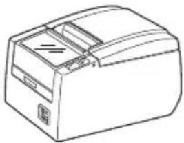
natural_image
Line drawing of a mechanical device with no visible text or symbolsCT-S801IIS
(Built-in power supply type) 36AD3/37AD3 AC adapter built in
AC power cord

Power switch cover
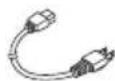
USB cable
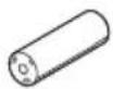
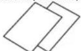
Sample paper roll
Quick Start Guide

Interface coverCD-ROM
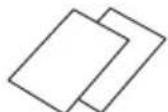
natural_image
Line drawing of a rectangular electronic device with ports and a lid (no text or symbols)CT-S801IIA (AC adapter type)
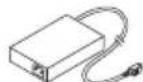
AC adapter (36AD2/37AD5)
Quick Start Guide
AC power cord
USB cable
Sample paper roll

Power switch cover

CD-ROM
Interface cover
1.3 Model Classification
Model numbers indicate printer features according to the following system.
CT - S801IIS 3 RS E - BK - P L M1
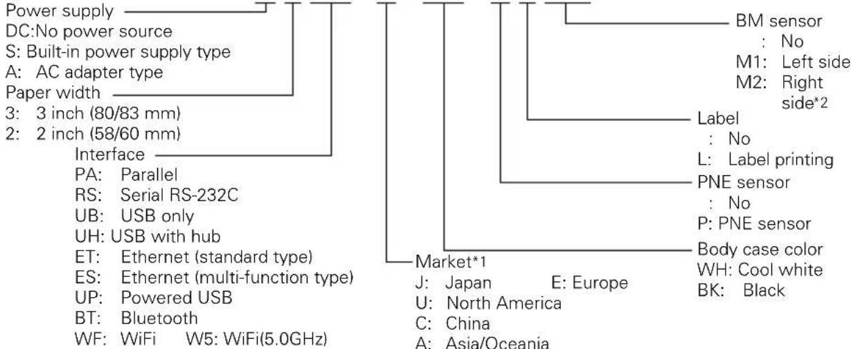
flowchart
graph TD
    A["Power supply"] --> B["DC: No power source"]
    A --> C["S: Built-in power supply type"]
    A --> D["A: AC adapter type"]
    A --> E["Paper width"]
    A --> F["3: 3 inch (80/83 mm)"]
    A --> G["2: 2 inch (58/60 mm)"]
    A --> H["Interface"]
    H --> I["PA: Parallel"]
    H --> J["RS: Serial RS-232C"]
    H --> K["UB: USB only"]
    H --> L["UH: USB with hub"]
    H --> M["ET: Ethernet (standard type)"]
    H --> N["ES: Ethernet (multi-function type)"]
    H --> O["UP: Powered USB"]
    H --> P["BT: Bluetooth"]
    H --> Q["WF: WiFi W5: WiFi(5.0GHz)"]

    B --> R["BM sensor : No"]
    B --> S["M1: Left side"]
    B --> T["M2: Right side*2"]

    R --> U["Label : No"]
    R --> V["L: Label printing"]

    S --> W["PNE sensor : No"]
    S --> X["P: PNE sensor"]

    T --> Y["Body case color WH: Cool white"]
    T --> Z["BK: Black"]

    W --> AA["Market*1"]
    X --> AA
    Y --> AA
    Z --> AA

    style A fill:#f9f,stroke:#333
    style AA fill:#ccf,stroke:#333
Certain combinations may not be available. Check with Citizen beforehand.
Notes:
*1: AC power cord, serial I/F screw, firmware and other specifications vary according to markets.
*2: 3-inch type only
1.4 Basic Specifications
| Item Specifications | ||||||
| Model CT-S801II | ||||||
| Print method Line thermal dot print method | ||||||
| Print width *1 80 mm/6 | 40 dots, 72 mm/576 dots, 64 mm/512 dots, 54.5 mm/436 dots,54 mm/432 dots, 52.5 mm/420 dots, 48 mm/384 dots, 45 mm/360 dots,48.75 mm/390 dots, 68.25 mm/546 dots | |||||
| Dot density 8 × 8 dots/mm (203 dpi) | ||||||
| Print speed 300 mm/s | fastest, print density 100%, 2400 dot-lines/s)150 mm/sec (1200 dot lines/sec) (for label specifications) | |||||
| Number of print columns*2 | — | Maximum number of characters(columns) | Dot configuration(dots) | |||
| Paper widthFont | 83 mm | 80 mm | 60 mm | 58 mm | ||
| F o | n | t | A | 5 | 3 | |
| F o | n | t | B | 7 | 1 | |
| F o | n | t | C | 8 | 0 | |
| Character size*3 | Font A: 1.50 × 3.00 mmFont B: 1.13 × 3.00 mmFont C: 1.00 × 2.00 mm | |||||
| Character type | Alphanumeric, international, PC437/850/852/857/858/860/863/864/865/866,WPC1252, katakana, ThaiCode 11/18 (1Pass/3Pass), TCVN-3 | |||||
| Liquid crystal display (LCD) | 128 × 32 dots STN liquid crystal, white/red LED backlight | |||||
| User memory | 384 KB (capable of storing user-defined characters and logos) | |||||
| Bar code types | UPC-A/E, JAN (EAN) 13/8 columns, ITF, CODE39, CODE128, CODABAR (NW-7),CODE93, PDF417, QR Code, GS1-DataBar | |||||
| Line spacing | 4.23 mm (1/6 inch) (changeable using commands) | |||||
| Paper roll | Paper roll: 83_-1^+0 mm/ 80_-1^+0 mm/ 60_-1^+0 mm/ 58_-1^+0 mm × maximum φ83 mmPaper thickness: 65 to 75 μm (core tube diameter: inner 12 mm/outer 18 mm)75 to 85 μm (core tube diameter: inner 25.4 mm/outer 32 mm)85 to 150 μm (core tube diameter: inner 25.4 mm/outer 32 mm:Supported by label-printing models only) | |||||
| Interface | Serial (RS-232C compliant), parallel (IEEE 1284 compliant), USB, USB with hub,Ethernet, Powered USB, Bluetooth(3.0), wireless LAN (802.11b/g or 802.11a/b/g/n) | |||||
| Cash drawer kick-out | Supports 2 cash drawers | |||||
| Buffer size | 4 k bytes/45 bytes | |||||
| Supply voltage | DC 24 V ±5% | |||||
| Power consumption | Approximately 45 W (normal printing), 3 W (standby) | |||||
| AC adapter*4(36AD2/3, 37AD3/5) | Rated input: AC 100 to 240 V, 50/60 Hz, 150 VARated output: DC 24 V, 2.1 A | |||||
| Item Specifications | |
| Weight | CT-S801IIS: Approx. 2 kg, CT-S801IIA: Approx. 1.6 kg |
| Outside dimensions | CT-S801IIS: 145 (W) × 192 (D) × 148 (H) mmCT-S801IIA: 145 (W) × 192 (D) × 120 (H) mm |
| Operating temperature and humidity | 5 to 45°C, 10 to 90% RH (no condensation) |
| Storage temperature and humidity | -20 to 60°C, 10 to 90% RH (no condensation) |
| Reliability Print head life | 150 km, 200 million pulses (at normal temperature/humidity, using recommended paper and paper thickness)Auto cutter life: 2 million cuts (at normal temperature/humidity, using recommended paper and paper thickness) |
| Safety standard *5 UL, C-UL, FCC Class A, TÜV-Bauart, CE Marking | |
Notes:
*1: When paper width is 83, 80, 60, or 58 mm.
*2: The number of printable columns is selected using a memory switch.
The numbers of columns noted in this table refer to typical models. The number of columns varies depending on specifications.
*3: Characters appear small because the dimensions include a blank area surrounding each character.
*4: The 36AD2/37AD5 is the AC adapter packaged as an accessory with the CT-S801IIA.
The 36AD3/37AD3 is the AC adapter built in to the CT-S801IIS.
*5: Compliant if the Citizen Systems AC adapter (36AD2/3, 37AD3/5) is used.
2.1 Printer Appearance
Names of parts
Paper cover
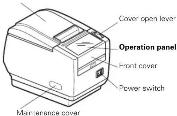
(Front view) (Rear view)
- Paper cover
Open to load paper.
(A label guide is attached to the paper cover of label-printing models.)
- Cover open lever
Use this lever to open the paper cover.
- Front cover
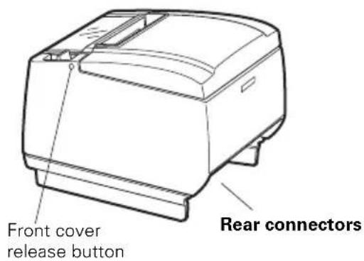
Open and close this cover to clear a cutter lock.

Refer to 4.3 Clearing a Cutter Lock (2)
- Front cover release button
Press this button to open the front cover.
- Power switch
Press this switch to turn the power on or off.
● Maintenance cover
Not applicable for this product.
Not used. Do not remove.
Do not open the maintenance cover.
Operation panel
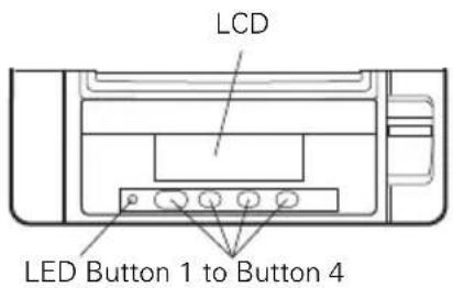
Examples are shown in the diagram of the LCD above on the right.
- LCD Indicates the printer's status, button names, types of errors, and messages.
- LED Lights green when the power is on, turns off when the power is off. Flashes green when receiving data. Lights red in special modes and in case of errors. Lights orange when paper is low (paper near-end) or the print head is hot.
- Button 1 to Button 4 Functions assigned to these buttons vary depending on the active mode. The buttons are called button 1, button 2, button 3, and button 4 in order from left to right.
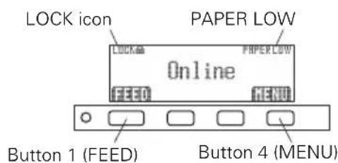
- FEED button Press this button to feed paper. To release a cutter lock, remove the cause of the lock, close the paper cover, and then press the FEED button.

Refer to 4.7 Error Messages
- MENU button Press and hold this button (for at least two seconds) to access the memory switch setting mode.

Refer to 5.3 Manual Setting of Memory Switches
● PAPER LOW Appears when the paper roll is near its end.
- LOCK icon
This icon indicates that the MENU button is inoperative.

Refer to 4.5 Key Lock Function
LCD in the vertical or wall mounted position
You can change the memory switch settings to invert the LCD if the printer is used in a vertical position or installed on a wall.
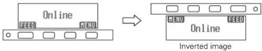

Refer to 5.3 Manual Setting of Memory Switches
Rear connectors
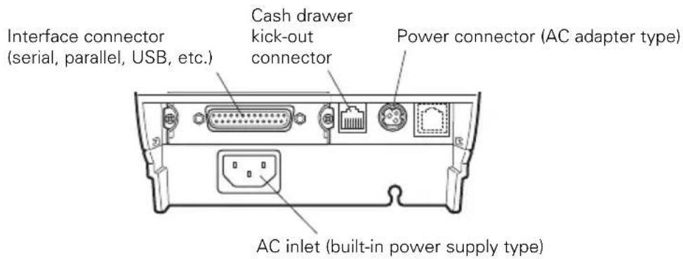
● Interface connector (serial, parallel, USB, etc.)
Connects to the interface cable.
The serial interface board is equipped with a DIP switch.
● Cash drawer kick-out connector Connects to the cable from the cash drawer.
● Power connector (AC adapter type) Connects to the AC adapter cable.
● AC inlet (built-in power supply type) Connects to the AC power cord.
2.2 Inside the Paper Cover
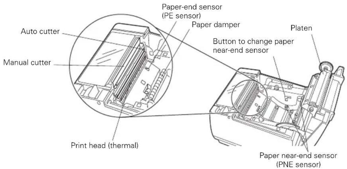
- Platen
Feeds the paper.
Do not remove the platen except to do maintenance.
● Paper near-end sensor (PNE sensor)
Detects when the paper is near the end of the roll. Adjust the position of the sensor to determine when it detects the end of the paper is near.
- Button to change paper near-end sensor
Change the position of the paper near-end sensor to match the paper being used.

Refer to 3.10 Adjusting the Paper Near-end Sensor
- Manual cutter
For cutting the paper manually when printing is finished.
- Auto cutter
Automatically cuts the paper when printing is finished.

Refer to 5.3 Manual Setting of Memory Switches
- Print head (thermal)
Prints characters and graphic data on paper (paper rolls).
● Paper end sensor (PE sensor)
Detects when there is no paper. Printing stops when this sensor detects there is no paper.
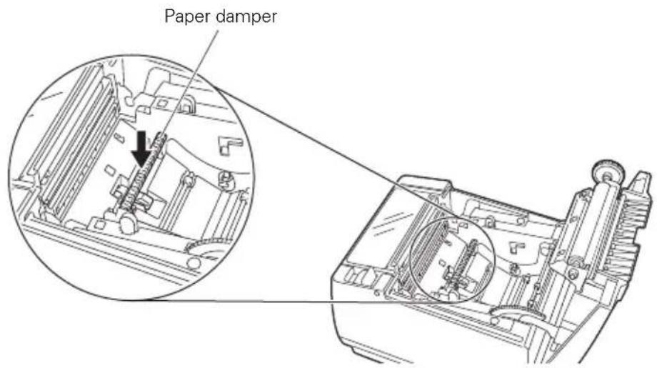
● Paper damper Assists paper feed.
The components in the figure below are used in label-printing models and black mark models.
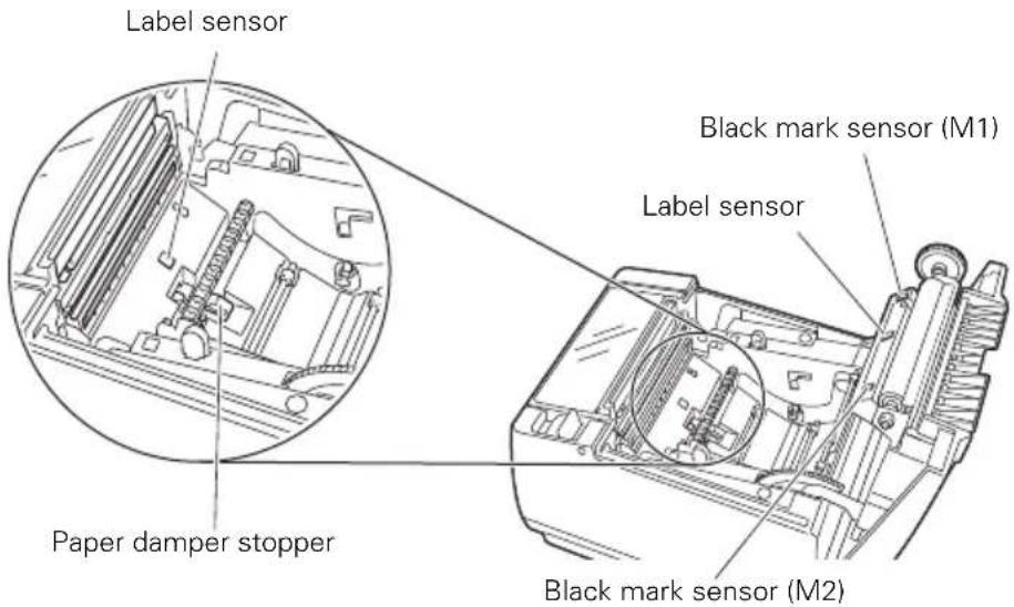
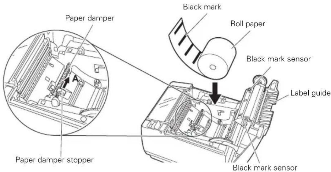
● Paper damper stopper Used to lock the paper damper.
- Black mark sensor Detects black marks on black mark paper. The sensor position is either M1 or M2, depending on the model classification.

Refer to 1.3 Model Classification
- Label sensor Measures the length of label paper.
2.3 Other Built-in Functions
- Buzzer
Buzzes when errors occur or when operations or command operations are performed.

Refer to 4.7 Error Messages
- User memory
You can save user-defined logo and character data in this memory. Data remains stored in this memory even if the printer is turned off. For information on how to save data, refer to the Command Reference.
- Memory switch
Setting of various kinds of functions can be stored in memory. Settings remain stored in the memory even if the printer is turned off.
- USB power supply OFF (When memory switch MSW6-3 is set to ON)
When the printer is connected to a PC by USB, turning off PC power or terminating the USB connection causes printer USB power to turn off three seconds later.
This mode is canceled when the PC is turned back on or when a USB connection is established.

CAUTION
■ The POWER LED is unlit when USB power supply is OFF, and the power OFF state cannot be identified.
- Pressing POWER while USB power is off does not turn on power immediately. After a while, USB power supply OFF is canceled and pressing POWER turns on power normally.
● Paper saving functions
Memory switches MSW8-3 through MSW8-5 can be used to configure the settings below, which save paper.
- Top margin suppression
The printer back feeds the paper before printing which reduces the blank space at the top edge of the paper.
The back feed amount can be specified.
- Line gap reduce
Automatically compresses the linefeed amount between lines. The compression ratio can be specified.
- Text compression vertical/horizontal
Makes the print size smaller.
The compression amount is specified by a combination of vertical and horizontal compression ratios.
● Auto side shift (MSW8-6)
This function dissipates heat load during frequent heat generation by a vertical ruled line or other specific head heating element.
If no data is received within 15 seconds after each cut or print, the print position is automatically slid N* dots to the right. The original print position is returned to at the next slide timing.
* N is the MSW8-6 setting value.

CAUTION
■ Before configuring the top margin suppression setting, first remove any partially cut paper from the printer. Failure to do so can cause the cut paper to be torn off by the next print operation, which can cause printer trouble.
■ Note the following precautions when using text compression.
- Compressed text is more difficult to read than the original text.
- Horizontally compressing text also makes the print range smaller, so the number of print lines does not change. Pay close attention to the print range when using narrow paper.
- Do not use compressed text when printing a bar code. Doing so may make the bar code unreadable.
If the right margin is too narrow, this may result in some print characters being cut off. This function is disabled under initial settings. To enable this function, use MSW8-6 to specify an appropriate value for the maximum slide amount.
3.1 Connecting the AC Power Cord
1. Turn off the power.
- ● For the built-in power type printer, connect the AC power cord to the AC inlet, and insert the plug into an electric outlet.
- For the AC adapter type printer, connect the cable connector of the AC adapter to the power connector. Next, connect the AC power cord to the AC inlet, and insert the plug into an electric outlet.
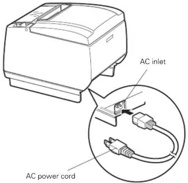
Built-in power supply type
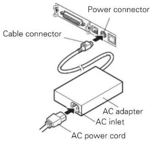
AC adapter type

CAUTION
■ Use only an AC adapter that complies with the specified ratings.
■ Always hold the AC adapter's cable connector by the connector when removing or inserting it.
■ Use an AC power source that does not also supply power to equipment that generates electromagnetic noise.
■ Pulling on the AC power cord may damage it, cause a fire, electric shock, or break a wire.
If a lightning storm is approaching, unplug the AC power cord from the electric outlet. A lightning strike may cause a fire or electric shock.
- Keep the AC power cord away from heat generating appliances. The insulation on the AC power cord may melt and cause a fire or electric shock.
■ If the printer is not going to be used for a long time, unplug the AC power cord from the electric outlet.
■ Place the AC power cord so that people do not trip on it.
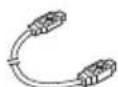
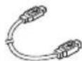
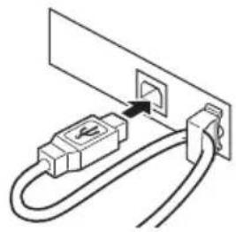
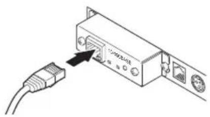
3.2 Connecting Interface Cables
- Turn off the power.
- Orient the interface cable correctly and insert it into the interface connector.
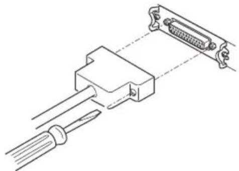
natural_image
Technical line drawing of a connector assembly with a USB cable and two connected ports (no text or symbols)Serial interface

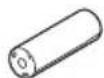
natural_image
Technical line drawing of a mechanical component with arrows indicating assembly or movement (no text or symbols)Parallel interface
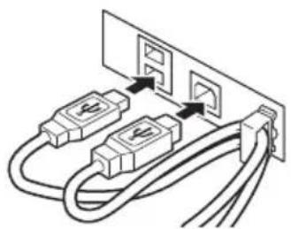
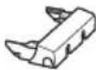
natural_image
Diagram of two USB connectors connected to a power outlet (no text or symbols)USB interface (hub type) USB interface
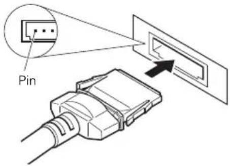
natural_image
Simple line drawing of a cable connector inserted into a socket (no text or symbols)Front view
Ethernet interface Powered USB interface
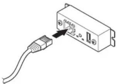
natural_image
Diagram of a USB cable inserted into an electronic device (no text or symbols visible)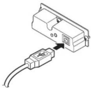
natural_image
Diagram of an electronic device showing a connector with an attached cable (no text or symbols present)Bluetooth + USB
Wireless LAN + LAN

CAUTION
■ Always unplug the AC adapter from the printer before connecting the printer to a Powered USB interface. Failure to do so may damage the host PC. For information about installing a Powered USB interface, contact your Citizen Systems dealer.
- Check the orientation of the Powered USB cable connector before connecting it. Insert it straight in so that the pins do not bend. Push it in until it clicks.
■ When disconnecting the cable, always hold the connector.
■ Be careful not to insert the USB interface cable into the cash drawer kick-out connector.
■ To connect more than one printer to a single computer via a USB interface you must change the serial number of the USB interface.
■ Hold the connector of the Ethernet interface cable perpendicular and straight when connecting or disconnecting it. Doing it at an angle may cause the connector to misconnect.
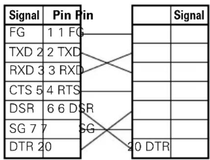
Use a serial interface cable with the connection layout shown below.
25-pin - 25-pin cable
PC Printer
9-pin - 25-pin cable
PC
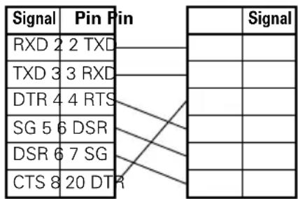

CAUTION
Place the interface cable so people do not trip on it.
3.3 Bluetooth Interface Board
Bluetooth status LED
natural_image
Pure electrical circuit lines without any symbolsSwitchStatus LED
The LED on the Bluetooth interface board on the rear of the printer indicates the status below.
| Status Description LED Status | ||
| Detection standby (Discoverable) | Standing by for detection and connection |  |
| Connection standby (Connectable) | Standing by for connection | 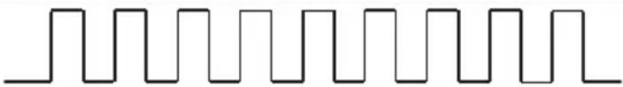 |
| iOS connection Data session unopened | 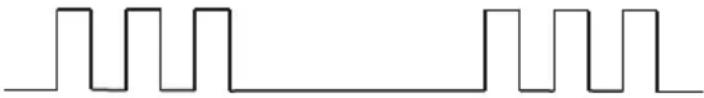 | |
| Communicating iOS: data session openedOther OS: connection established and communication in progress | 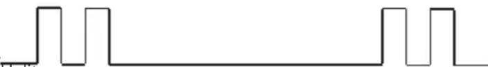 | |
| Error Error or settings being configured | ||
Pairing operation
You need to perform the operations below the first time you establish a Bluetooth connection for Bluetooth data communication.
A: Detect Bluetooth devices
B: Configure pairing settings
A: Detecting Bluetooth devices
Confirm that Bluetooth is enabled on the host PC before searching for Bluetooth devices.
This product will show up as "CT-S801II_XX"(XX is last 2 digits of unique BD address.) when it is detected.
Select this product from among the detected devices.
Note: You can search for devices and change the names.
When memory switch MSW13-5 is set to "No Response" nothing is displayed by device detection.
You can temporarily switch this setting to device detection (detect mode) by pushing the switch on the Bluetooth interface board. Detect mode is exited when the connection between the host PC is terminated.
B: Configuring pairing settings
Normally, selecting the printer during device detection will transition directly to pairing settings.

CAUTION
Some host PC configurations and models may not transition directly to pairing settings after the printer is selected during device detection.
The operation required to configure pairing settings depends on whether SSP (secure simple pairing) is enabled on the host PC.
If SSP is enabled on the host PC, pairing can be achieved without additional operations.
If SSP is disabled on the host PC, you will be prompted to input a passkey.
Input the passkey as described below.
Passkey Last four digits of the address on the self test printout (Letters A through F are uppercase) Example: If the address is 01:23:45:67:89:AB the passkey is 89AB.
If you delete paring information from the host PC without deleting the corresponding pairing information on the printer, the printer may not show up if you detect devices again with the host PC.
To delete printer pairing information, hold down the switch on the Bluetooth interface board for two seconds or more.
Deleting pairing information on the printer will put the printer into discovery mode.
Auto reconnection
With iOS device Bluetooth communication, a connection between a paired iOS device and the printer is not automatically restored after it is lost. However, when auto reconnection is enabled, the printer tries to reconnect with an iOS device after two-way communication is enabled and automatically restores the connection.

CAUTION
This function is enabled when shipped from the factory. (MSW13-6)
Auto reconnection can take some time to connect when the host is not an iOS device.
■ Even if the partner device is an iOS device, the conditions below can interfere with the auto reconnection function.
- When you want Bluetooth communication to cut off after printing is complete
- When there are multiple iOS devices printing on the same printer
Under such conditions, disable auto reconnection.
Enabling and disabling auto reconnection
To change the setting of this feature, the following method is provided.
Press the FEED button 3 times during self test -> Auto reconnect = Valid Press the FEED button 4 times during self test -> Auto reconnect = Invalid
At the end of self test, new setting will be printed as Auto reconnect [Valid] or [Invalid]

Refer to 4.4 Function Test Mode
3.4 Ethernet (LAN) Interface Board
This section provides an overview of the Ethernet (LAN) interface board. For details about this board, refer to the separate manual.
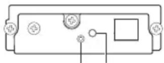
Panel button operation
Board operations are performed using the panel button on the Ethernet board. You can use the button to print setup information and to return the board to its factory settings.
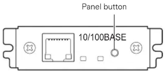
● Printing network setup information
Press the panel button.
- Entering setting mode
Hold down the panel button. A buzzer* will sound once to indicate that setting mode has been entered.
- You can use setting mode to read factory settings and to print firmware information.
- If you do not perform any operation for three seconds while in setting mode, a buzzer* will sound once to indicate the board has returned to normal mode.
* Depending on settings, the buzzer may not sound.
- Returning to factory settings Enter the board setting mode, and then hold down the panel button. This returns the board to its factory settings.

CAUTION
■ The board will automatically restart after this operation is complete.
■ If settings are configured to obtain an IP address from a DHCP server automatically, the new IP address may be different from the previous one.
LED Functions
The tables below explain how to interpret LED indications.
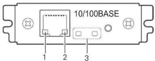
1. Network transmission speed
| Transmission speed LED (green) | |
| 100Mbps Lit | |
| 10Mbps/Not connected Unlit | |
2. Network status
| Status LED (yellow) | |
| Connected Lit | |
| Not connected Unlit | |
| Data transmission in progress | Flashing |
3. Board status
| Status LED (green) | LED (red) Description | ||
| No printer connection Unlit — Board is not connected with a printer. | |||
| Connecting with printer | Lit | — Board is connected with a printer. | |
| No network connection | — | Unlit | Board is not connected with a network. |
| Getting IP address | — | Flashing (0.5-second cycle) | Getting an IP address from the DHCP server. |
| Connected with network | — | Lit | Network connection complete. |
| Resource error | Alternate flashing (0.5-second cycle) | Board is unable to operate normally. | |
| System error | Alternate flashing (0.1-second cycle) | Board is unable to operate normally. | |
Changing network settings
You can use a web browser to access a special settings page to check and change board settings.
- Accessing the special settings page
-
Use a web browser to access the URL of the special settings page. Specify the IP address assigned to the printer as the URL. (Example: For an IP address of 169.254.1.10, input: http://169.254.1.10.)
-
This displays the special settings page menu page.
Print server homepage
Menu
Print server configuration
Printer status
LAN I/F information
Copyright (C) 2010 CITIZEN SYSTEMS JAPAN CO.,LTD. All Rights reserved.
- Select "Print server configuration" to display the setting screen. For details about settings, refer to the separate manual.
3.5 Wireless LAN Interface Board
This section provides an overview of the wireless LAN interface board. For details about this board, refer to the separate manual.
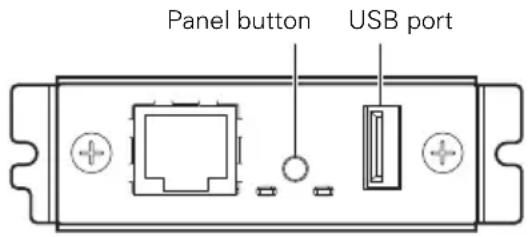
Connecting USB dongle
Connect the USB WiFi dongle that comes with the wireless LAN interface board to the USB port connector.
To improve signal quality, you can also use a USB extension cable and adjust the position of the dongle.
Panel button operation
Board operations are performed using the panel button on the rear of the LAN board.
● Enabling wireless LAN connection
Turn on the printer. Operation of this board will start about 20 seconds later.
● Printing wireless LAN setup information Press the panel button.
- Entering setting mode Hold down the panel button. A buzzer* will sound once to indicate that setting mode has been entered.
- You can use setting mode to read factory settings.
- If you do not perform any operation for three seconds while in setting mode, a buzzer* will sound once to indicate the board has returned to normal mode.
* Depending on the printer model and settings, the buzzer may not sound.
- Returning to factory settings Enter the board setting mode, and then hold down the panel button. This returns the board to its factory settings.

CAUTION
■ The board will automatically restart after this operation is complete. After clearing settings, you will need to re-configure wireless LAN settings.
LED Functions
The tables below explain how to interpret LED indications.
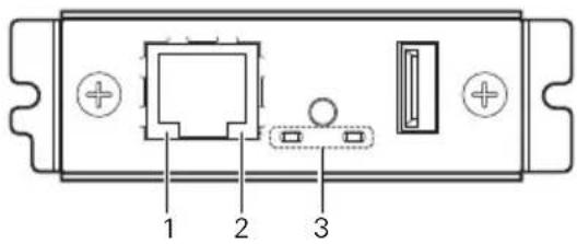
1. Wired LAN transmission speed
| Transmission speed LED (green) | |
| 100Mbps Lit | |
| 10Mbps/Not connected Unlit | |
2. Wired LAN connection/transmission status
| Connection status LED (yellow) | |
| Connected Lit | |
| Not connected Unlit | |
| Data transmission in progress | Flashing |
3. Wired/Wireless LAN status
| Connection status LED | (green) LED (red) | Description | ||
| No printer connection Unlit — Board is not connected with a printer. | ||||
| Printer connection | No network connection | Lit | Unlit | Board is connected with a printer. |
| Connected by wired LAN | Lit | Flashing (1-second cycle) | Getting an IP address from the DHCP server over wired LAN. | |
| Wired LAN operation | Lit | Lit | Network operation being performed over wired LAN. | |
| Connected by wireless LAN | Flashing (2-second cycle) | Flashing (1-second cycle) | Connecting to an access point or getting an IP address from the DHCP server over wireless LAN. | |
| Wireless LAN operation | Flashing (2-second cycle) | Lit | Network operation being performed over wireless LAN. | |
| Resource error | Alternate flashing (1-second cycle) | Board is unable to operate normally. | ||
| System error | Alternate flashing (0.2-second cycle) | Board is unable to operate normally. | ||
Web Manager
The wireless LAN interface board has a Web Manager function that can be used to connect to the board with a web browser and change board settings.
Starting up Web Manager
- Start up a web browser.
- In the address field, input the board's IP address and then press [Enter].

HOME Screen
This is the Web manager home screen.
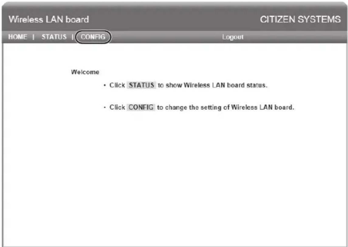
Here, press the [CONFIG] button.
CONFIG Screen
This will display the Login dialog box shown below. Log in as an administrator and then configure wireless LAN interface board settings.

- User Name Input a board administrator user name. (Initial setting: admin)
- Password Input the administrator user password. (Initial setting: admin)
- [Login] button After inputting an administrator user name and password, click the [Login] button. This displays the setting screen.
For details about settings, refer to the separate manual.
3.6 Connecting the Cash Drawer
- Turn off the power.
- Confirm the orientation of the cash drawer kick-out cable connector and connect it to the cash drawer kick-out connector at the back of the printer.
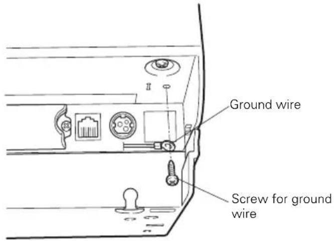
- Remove the screw for the ground wire.
- Screw the cash drawer's ground wire to the body of the printer.
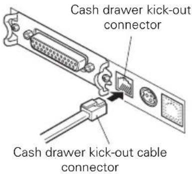

CAUTION
■ Connect only the cash drawer kick-out cable connector to the cash drawer kick-out connector. (Do not connect a telephone line.)
■ Signals cannot be output from the cash drawer kick-out connector while printing.
(1) Connector pin configuration
| No. | Signal Function | 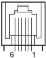 |
| 1 | FG Frame ground Connector used: | |
| 2 | DRAWER1 Cash drawer 1 drive signal | |
| 3 | DRSW Cash drawer switch input | |
| 4 | VDR Cash drawer drive power supply | |
| 5 | DRAWER2 Cash drawer 2 drive signal | |
| 6 | GND Signal ground (common ground on circuits) |
TM5RJ3-66 (Hirose) or equivalent
Applicable connector: TM3P-66P (Hirose) or equivalent
(2) Electric characteristics
1) Drive voltage: 24 VDC
2) Drive current: Approx. 1 A max. (not to exceed 510 ms.)
3) DRSW signal: Signal levels: "L" = 0 to 0.8 V, "H" = 2 to 3.3 V
(3) DRSW signal
DRSW signal status can be tested with the DLE+EOT, GS+a, or GS+r command or at pin 34 on the parallel interface port.
(4) Drive circuit
Cash drawer kick-out connector
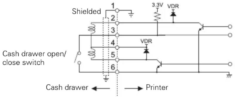

CAUTION
■ Cash drawers 1 and 2 cannot be operated at the same time.
■ The solenoid used for the cash drawer should be 24 Ω or more. Do not allow the electric current to exceed 1 A. Excessive current could damage or burn out the circuits.
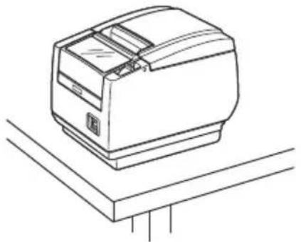
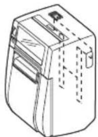
3.7 Precautions for Installing the Printer
The printer can be used horizontally, vertically, or installed on a wall. However, the CT-S801IIS (built-in power supply type) cannot be used vertically or installed on a wall.
Use the optional stand for vertical applications, and the optional brackets for wall installations. Please refer to the manual for further details.
natural_image
Line drawing of a mechanical device with no visible text or symbolsHorizontal position
natural_image
Line drawing of a mechanical device with no visible text or symbolsWall installation

natural_image
Line drawing of a mechanical device with no visible text or symbolsVertical position
You can change the memory switch settings to invert the LCD if the printer is used in a vertical position or installed on a wall.

Refer to 5.3 Manual Setting of Memory Switches

Refer to 2.1 Printer Appearance (LCD in the vertical or wall mounted position)
Change the paper near-end sensor settings for vertical and wall installations. (The factory setting for the paper near-end sensor is for horizontal installations.)

Refer to 3.10 Adjusting the Paper Near-end Sensor

CAUTION
Do not use the printer under the following conditions.
■ Locations subject to vibration or instability.
■ Locations that are very dirty or dusty.
■ Locations where the printer is not level.
- The printer may fall and cause an injury.
• The quality of printing may deteriorate.
■ Oriented other than as specified.
- The printer may malfunction, be damaged, or cause an electric shock.
Precautions for horizontal installations
■ Do not set cutting to full cut. Doing so may cause cutter jams.
Precautions for vertical/wall installations
■ Adjust the paper near-end sensor.
Precautions for vertical installations
■ The optional stand may fall over when you pull on partially cut thick paper. Do not use thick paper.
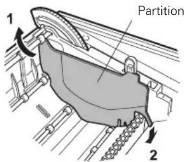
3.8 Partition for Paper Roll
Set the partition to the width of the paper roll you are loading.
The partition is set at the factory to the position shown below.
● For 3-inch type: 80-mm wide paper roll
- For 2-inch type: 58-mm wide paper roll, 60-mm wide paper roll (2-sheet partition installed.)
-
Turn off the power.
-
Pull the cover open lever forward and open the paper cover.
-
Set the partition in a slot that matches the size of the paper roll you are using. However, to use an 83-mm wide paper roll, remove the partition. Or, when you are using a 60-mm wide paper roll with the 2-inch type, remove the partition installed for 58-mm.
-
Refer to "5.3 Manual Setting of Memory Switches" to change the paper width settings.
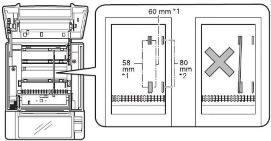
Notes:
*1: 2-inch type (58/60 mm)
*2: 3-inch type (80/83 mm)

CAUTION
Make sure the partition is not slanted when setting it for 58-mm or 60-mm paper rolls.
3.9 Setting the DIP Switch on the Serial Interface Board
- Turn off the printer and unplug the power cord from the electric outlet.
- Remove the mounting screws of the serial interface board.
- Remove the serial interface board from the printer.
- Set the DIP switch according to the following table.
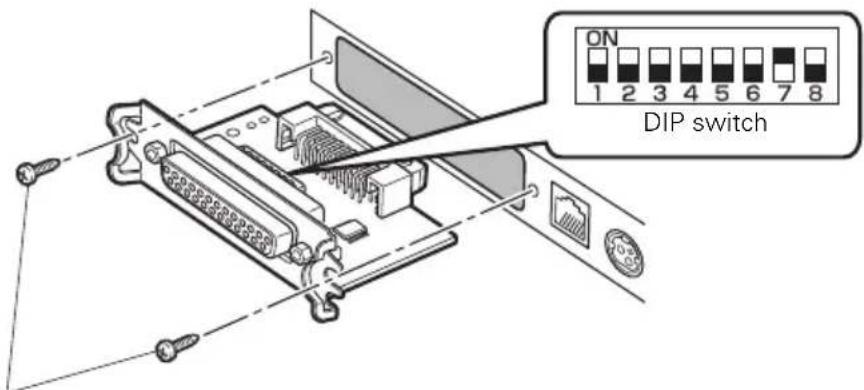
Serial interface board mounting screws

CAUTION
When setting the DIP switch, do not remove any screws except the serial interface board mounting screws.
The function of each switch is shown below. (Shaded values are factory settings. However, factory settings differ depending on the destination market.)
| Switch no. | Function ON OFF | ||
| 1 | Communication condition setting | According to DIP switch settings | According to memory switch settings |
| 2 | Hand shake XON/XOFF | DTR/DSR | |
| 3 | Bit length 7 bits | 8 bits | |
| 4 | Parity check Yes | No | |
| 5 | Parity selection Even parity | Odd parity | |
| 6 | Baud rate selection | Refer to table below. | |
| 7 | |||
| 8 | INIT Reset | Invalid | |
Baud rate selection
| Baud rate (bps) | Switch no. | |
| 6 | 7 | |
| 2400 OFF OFF | ||
| 4800 | ON | OFF |
| 9600 OFF ON | ||
| 19200 ON ON | ||
When switch no. 1 is set to OFF, you can use a command or a memory switch to select 1200, 38400, 57600, or 115200 bps.
3.10 Adjusting the Paper Near-end Sensor
Change the settings of the paper near-end sensor to set the position at which the near-end of the paper is detected.
- Use a pointed object, such as a pen, to gently press the button to change the paper near-end sensor.
- Press and hold down the button while moving the paper near-end sensor up, down, right and left. The sensor positions are shown below for the various diameters of the paper roll used.
When paper thickness is 75 μm or less (Unit: mm)
| Sensor position | Exterior diameter when detected as near end | Exterior/ interior diameter of core of paper roll used |
| A, a | Approximately 31 | 18/ 12 |
| B*, b | Approximately 23 | 18/ 12 |
| C Paper near-end sensor function is off | ||
When paper thickness is 75 μm or more (Unit: mm)
| Sensor position | Exterior diameter when detected as near end | Exterior/ interior diameter of core of paper roll used |
| A, a | Approximately 41 | 32/ 25.4 |
| B*, b | Approximately 34 | 32/ 25.4 |
| C Paper near-end sensor function is off | ||
Note:
*: Position of sensor when shipped from factory. However, factory settings differ depending on the destination market.

CAUTION
The diameter of the roll of paper that is detected is an estimate. Some variations may occur depending on the paper.
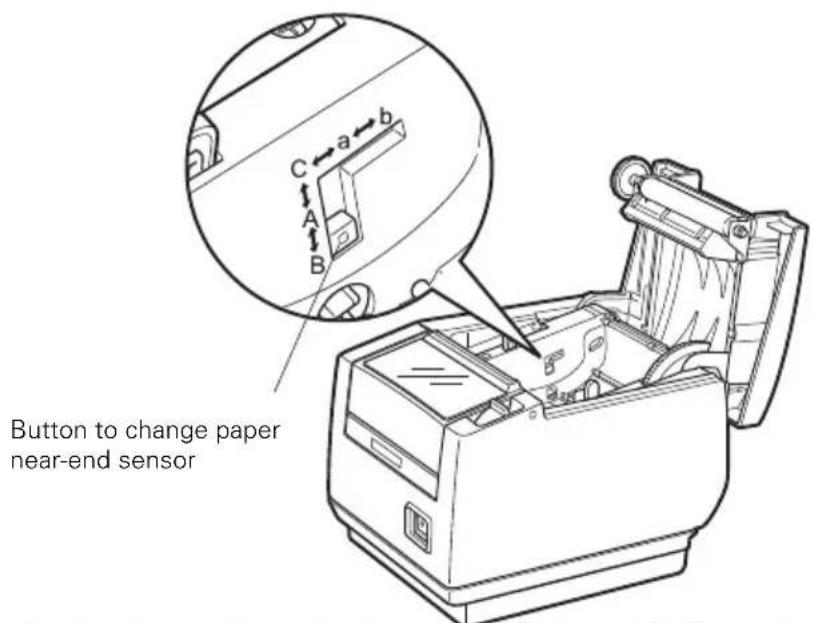
("A" and "B" are for horizontal installations, and "a" and "b" are for vertical or wall installations.)
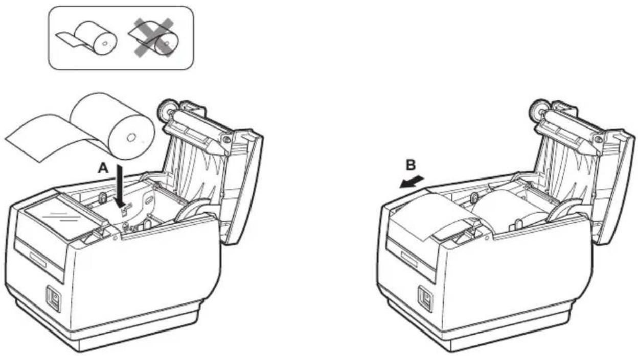
3.11 Loading Paper
- Turn on the power.
- Pull the cover open lever forward and open the paper cover.
- Lock the paper damper when using label paper or thick paper.
- Load the paper roll so that the printable side of the paper is facing down, as shown by arrow A.
- Pull a few cm of paper straight out in the direction of arrow B.
- Close the paper cover until you hear a click. Paper is fed and cut automatically (by the factory setting).

Refer to 5.3 Manual Setting of Memory Switches

CAUTION
■ Always use the specified types of paper rolls.
■ Confirm that the paper roll is set correctly.
■ If the paper is skewed and not coming straight out of the paper cover, open it and straighten the paper.
■ Always pull a few cm of paper straight out of the printer if you open the paper cover while paper is loaded.
■ Press on the center of the paper cover to close it securely.
■ Be careful of paper cuts while loading the paper.
■ Do not touch the print head, manual cutter, or auto cutter while the paper cover is open. Doing so may cause a burn or cut.
3.12 Calibrating the Paper Sensor
Calibrate the paper sensor to suit the actual paper you are using before using label paper or black mark paper.
When you perform the procedure below, the printer will automatically feed the paper loaded in it and set the sensor to the optimum sensitivity. Or, the paper type is automatically selected.
To load label paper
- Turn off the power.
- Pull the cover open lever forward and open the paper cover.
- Press in on the paper damper in the direction indicated by the arrow until it clicks.
- Peel off the first label of the label paper.
Peel off a few labels, if they are short, so at least 5 cm of paper is uncovered. - Load the paper roll so that the printable side of the paper is facing down.
- Adjust the paper position so the part from which you peeled the label is located above the label sensor.
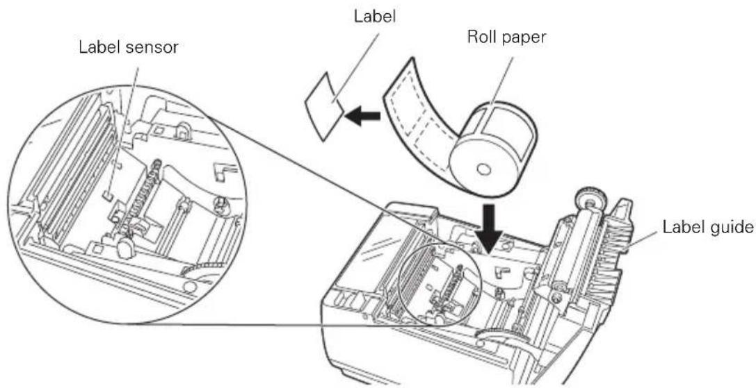
- Close the paper cover.
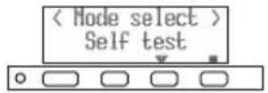
8. While holding down button 1, turn on the power.
The function test mode starts and "Self test" appears on the LCD.
9. Press button 3 ( ) five times.
"Calibrate Label" appears on the LCD.
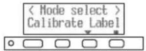
10. Press button 4 ( )
Paper sensor calibration starts.
- "Online" will appear on the LCD if paper sensor calibration is successful. If paper sensor calibration fails, an error message will appear on the LCD.
To load black mark paper
- Turn off the power.
- Pull the cover open lever forward and open the paper cover.
- Slide the paper damper stopper in the direction indicated by arrow A and release the paper damper lock.
Lock the paper damper whenever you are using black mark label paper. - Load the paper roll so that the printable side of the paper is facing down.
- Check to make sure the paper is above the paper damper.
- Adjust the paper position so no black mark is located under the black mark sensor.
7. Close the paper cover.
8. While holding down button 1, turn on the power.
The function test mode starts and "Self test" appears on the LCD.
9. Press button 3 ( ) four times.
"Calibrate BM" appears on the LCD.
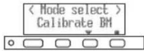
10. Press button 4 ( ).
Paper sensor calibration starts.
- "Online" will appear on the LCD if paper sensor calibration is successful. If paper sensor calibration fails, an error message will appear on the LCD.

Refer to 4.7 Error Messages

Refer to 3.13 Selecting a Paper Type

CAUTION
■ Do not allow more than 10 sheets of cut paper to collect in the paper catch tray (label guide). More than 10 sheets of paper may cause a paper jam.
■ Be sure to re-calibrate the paper sensor whenever you change to another type of black mark paper.
3.13 Selecting a Paper Type
Select a paper type in "Paper select" in the Function Test Mode to change the type of paper being used.
- Load paper.
- While holding down button 1, turn on the power.
The function test mode starts and "Self test" appears on the LCD.
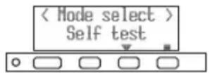
- Press button 3 () three times.
"Paper select" appears on the LCD.

- Press button 4 ().
"Thermal roll" appears on the LCD.
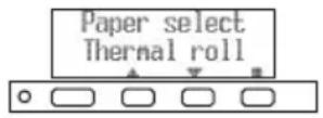
-
Each press of button 3 ( ) cycles through the paper types on the LCD as follows: Thermal roll → Black mark → Label → Thermal roll. Keep pressing button 3 ( ) until the paper type you want to use is displayed.
-
Press button 4 ().

Refer to 3.11 Loading Paper
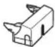
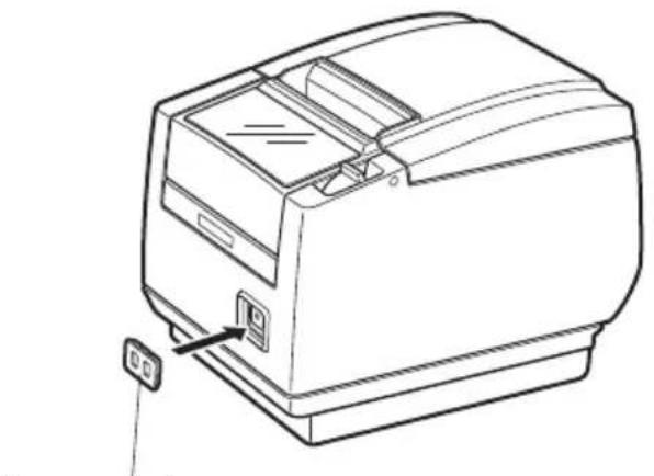
3.14 Attaching the Power Switch Cover
Attach this cover to prevent the power switch from being used.
- Press the power switch cover onto the power switch compartment until it clicks.
natural_image
Line drawing of a mechanical device with a button and mounting bracket (no text or symbols)Power switch cover
Put a screwdriver or other pointed object into the grooves on the power switch cover to remove it.
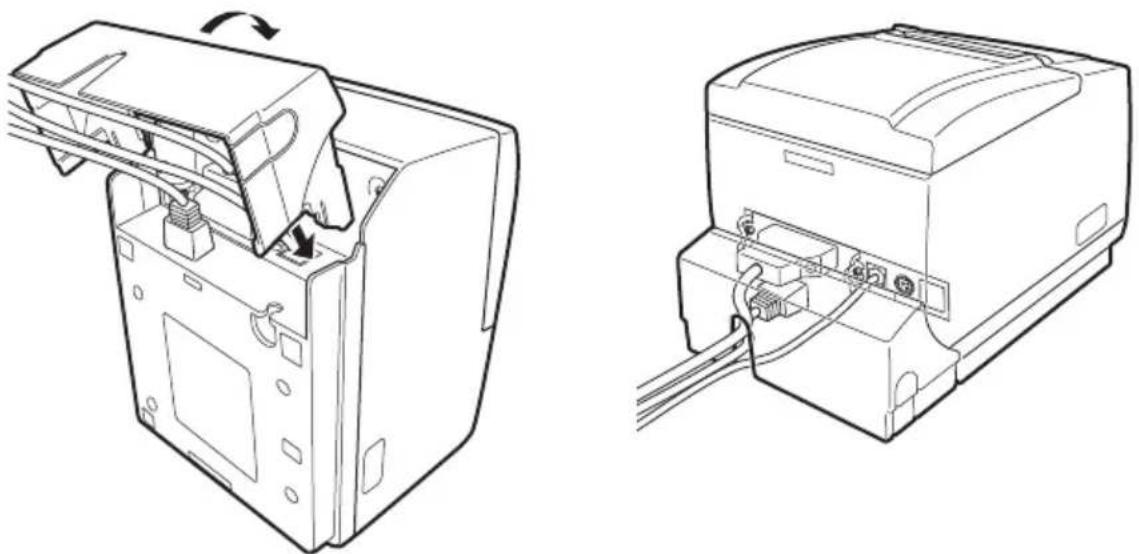
3.15 Attaching the Interface Cover
Attach the interface cover to the back of the printer.
The shape of the interface cover is different depending on the type of power source.
- Press the interface cover as shown in the diagram until you hear it click.
natural_image
Technical line drawing of two views of a device showing internal components and wiring (no text or symbols)CT-S801IIS
3.16 Removing the Interface Cover
Press in on both sides at the point indicated by A to remove the interface cover.
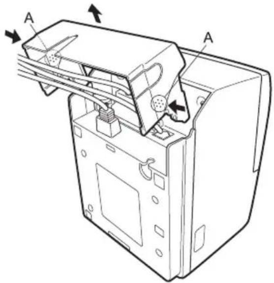
CT-S801IIS
3.17 Installing a Driver
Drivers are included on the CD-ROM that comes with the printer. Install the driver required by your printer.
For information about driver installation, functions, and operations, see the information provided on the CD-ROM for each driver.
Visit the site below to download the latest driver versions and information.
http://www.citizen-systems.co.jp/english/support/download/printer/driver/
3.18 Precautions for Creating Applications and Practical Operations
If printing is done immediately after the paper is partially cut and torn off, the top of the next print out may be distorted.
We recommend advancing the paper one line after cutting before printing.
If you are using a serial interface that has a slow data transmission speed, streaks may appear in the printouts when you are printing graphics or gradated text, which require large amounts of data.
USB interfaces may be susceptible to the effects of electromagnetic interference from the host or environment.
If this is the case, try using a cable with ferrite cores on both ends, which are very effective at eliminating EMI.
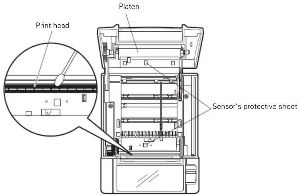
4.1 Periodic Cleaning
A dirty print head or platen may reduce printing quality or cause malfunctions. Also, if paper dust collects on the sensor's protective sheet, paper cannot be detected correctly. We recommend cleaning the printer periodically (every 2 to 3 months) as shown below.
- Turn off the power.
- Pull the cover open lever forward and open the paper cover.
- Wait a few minutes until the print head cools.
- Use a cotton swab dampened with ethyl alcohol to wipe off any dirt and dust that is on the print head and platen.
- Use a cotton swab dampened with a little water to wipe off the sensor's protective sheet.
Make sure there are no water drops on the cotton swab before wiping.

CAUTION
■ The print head is hot immediately after printing. Do not touch it.
■ Do not touch the print head with bare hands or metal objects.
- Do not use alcohol or cleansers to clean the surface of the sensor's protective sheet. Doing so may fog the sensor's protective sheet.
Paper scraps may stick to the platen when adhesive labels are full cut depending on the printer's environment, the diameter of the paper roll, and the quality of the label backing.
4.2 Clearing a Cutter Lock (1)
The message “Cutter lock” may appear and the auto cutter blade may remain extended because a foreign object or paper jam is obstructing it.
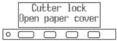
If "Cutter lock" is displayed, clear the locked cutter as shown below.
- Turn on the power.
- Pull the cover open lever forward and open the paper cover.
- Remove any jammed paper including any scraps of paper. (Remove the paper roll that is loaded in the holder also.)
- Reload the paper roll and close the paper cover.

CAUTION
■ The print head is hot immediately after printing. Do not touch it.
■ Do not touch the print head with bare hands or metal objects.
After doing the procedure in "Clearing a Cutter Lock (1)" and then opening the paper cover, if the blade of the auto cutter is extended, do the procedure in "Clearing a Cutter Lock (2)".

Refer to 4.3 Clearing a Cutter Lock (2)
4.3 Clearing a Cutter Lock (2)
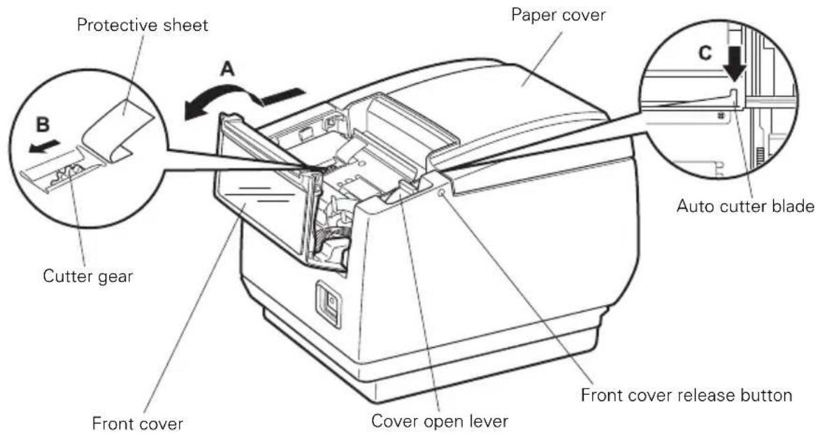
The paper cover is designed to be opened if the cutter locks by pressing the cover open lever. If this does not open the paper cover, use the following procedure to clear the locked cutter.
-
Turn off the printer and unplug the power cord from the electric outlet.
-
Press the front cover release button with a pointed object, such as a pen, and open the front cover in the direction of arrow A.
Slide the front cover 3 to 4 mm in the direction of arrow A and rotate it forward.
- Lift the protective sheet and turn the cutter gear in the direction of arrow B to return the auto cutter to a position where the paper cover can be opened.
Turn the cutter gear until the auto cutter blade retracts in the direction of arrow C. If the blade of the auto cutter does not move when you turn the cutter gear in the direction of arrow B, turn it in the other direction.
-
Pull the cover open lever forward and open the paper cover.
-
Remove whatever caused the cutter to lock.
-
Close the front cover.
Rotate the front cover in the opposite direction of arrow A and then slide it until it clicks.
-
Load a paper roll and close the paper cover.
-
Insert the power cord plug into an electric outlet and turn the power on.
Check that the LED lights green.

CAUTION
■ Before starting to do maintenance work, be sure to turn off the printer and unplug the power cord from the electric outlet.
■ Be careful not to touch the manual cutter while the front cover is open.
■ Be careful not to touch the opening for the auto cutter while the paper cover is open.
■ The print head is hot immediately after printing. Do not touch it.
■ Do not touch the print head with bare hands or metal objects.
■ If the above procedure does not retract the auto cutter, contact your Citizen Systems dealer.
4.4 Function Test Mode
Press and hold button 1 while turning on the printer to access the function test mode.
Use button 3 ( ) to select a function, use button 4 ( ) to execute the function.
Except for the self test and printing memory switch settings, all functions are for service personnel only. Do not operate those functions.
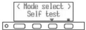
Self test
- While paper is loaded, press and hold button 1 while turning the power on.
The function test mode starts and "Self test" appears on the LCD.
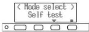
- Press button 4 ().
Self test starts. The printer prints its model name, version, DIP switch settings, memory switch settings, and a list of built-in fonts.
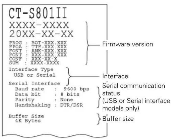
Note:
*: Printers with a USB interface do not have DIP switches, so the DIP switches all appear off on the self test printout.
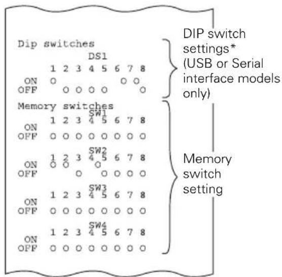
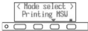
Printing memory switch settings
- While paper is loaded, press and hold button 1 while turning the power on. The function test mode starts and "Self test" appears on the LCD.
- Press button 3 ( ).▼ "Printing MSW" appears on the LCD.
- Press button 4 ( ). ■ A list of the current memory switch settings starts printing.
The function test mode has the following sub modes.
| Function Description | |
| Self test Runs self test. | |
| Printing MSW Prints memory switch settings. | |
| Quick Setting *1 Sets the memory switches to be compatible with specific models. | |
| Paper select *2 Selects the paper type. | |
| Calibrate BM *2 Used to calibrate the black mark sensor. | |
| Calibrate Label *2 Used to calibrate the label sensor. |
Notes:
*1: The memory switches are automatically set to their optimum settings by selecting the manufacturer and model of the printer being replaced.
*2: Label-printing models and black mark models.
Selected item
| Manufacturer | Model | Paper width | Character space |
| CITIZEN | CBM1000 | 58 mm | — |
| 80 mm | — | ||
| CT-S300 | 58 mm | — | |
| 80 mm | — | ||
| CT-S2000 | 58 mm | — | |
| 60 mm | — | ||
| 80 mm | — | ||
| 83 mm | — | ||
| EPSON | T88 | 58 mm | 0dot |
| 1dot | |||
| 80 mm | 0dot | ||
| 1dot | |||
| 203dpi | 58 mm | — | |
| 60 mm | — | ||
| 80 mm | — |

Automatic memory switch settings
| MSW2-4 Full Col Print | MSW3-7 CBM1000 Mode | MSW8-1 Print Width | MSW6-2 Character Space |
| Auto linefeed | Valid | 432dots | — |
| Auto linefeed | Valid | 576dots | — |
| WaitData | Invalid | 384dots | — |
| WaitData | Invalid | 576dots | — |
| Auto linefeed | Valid | 432dots | — |
| Auto linefeed | Valid | 436dots | — |
| Auto linefeed | Valid | 576dots | — |
| Auto linefeed | Valid | 640dots | — |
| WaitData | Invalid | 360dots | 0dot |
| WaitData | Invalid | 390dots | 1dot |
| WaitData | Invalid | 512dots | 0dot |
| WaitData | Invalid | 546dots | 1dot |
| WaitData | Invalid | 420dots | — |
| WaitData | Invalid | 436dots | — |
| WaitData | Invalid | 576dots | — |
4.5 Key Lock Function
Press and hold the MENU button while the printer is running to be able to change the memory switch settings.
Activate the key lock to prevent making changes by mistake.

Button 3
Setting the key lock
To set the key lock, press and hold button 3 (for at least three seconds).
MENU disappears, and the LOCK icon appears.
In this condition, it is not possible to enter the memory switch setting mode even if you press and hold the MENU button.
Releasing the key lock
To release the key lock, press and hold button 3 (for at least three seconds). The LOCK icon disappears, and MENU appears.
4.6 Hexadecimal Dump Printing
Print received data in hexadecimal. If problems such as missing or duplicated data occur, this function allows you to check whether or not the printer is receiving data correctly.
How to do hexadecimal dump printing
- Load paper.
- While the paper cover is open, press and hold button 1 while turning the power on, and then close the paper cover. Enter HEX dump print mode.
- The printer prints "HEX dump print mode" followed by the received data printed in hexadecimal numbers and some characters.
How to stop hexadecimal dump printing
Do one of the following to stop printing.
- Press button 1 (FEED) three times in a row
- Turn off the power
● Receive a reset command from an interface

CAUTION
■ The printer prints “.” if there is no character corresponding to the data.
■ None of the commands function during hexadecimal dump printing.
■ If print data does not cover a complete line, press button 1 (FEED) to advance the paper.
Print example
HEX dump print mode
61 62 63 64 65 66 67 0A 0D 0D 0D 0D abcdefg.....
0D 0D 0D .....
4.7 Error Messages
- Paper end
The end of the roll of paper is detected at two stages, paper near-end and paper-end.
When paper near-end is detected, "PAPER LOW" appears on the LCD and the LED lights orange. Prepare a new paper roll.
When paper-end is detected, "Paper end" appears on the LCD and the LED lights red. Load a new paper roll.
- Paper cover open
Do not open the paper cover during printing. If the paper cover is opened, the LED and LCD light red. Check the paper and always pull a few cm of paper straight out of the printer before closing the paper cover. Printing resumes. Sending a command to resume printing may be required depending on the memory switch setting.
- Cutter lock
If the auto cutter cannot move because of a paper jam or something else, the LED and LCD light red. Remove the cause of the trouble and press button 1 (FEED). If the auto cutter still does not operate and the paper cover does not open, refer to "4.3 Clearing a Cutter Lock (2)".

Refer to 4.3 Clearing a Cutter Lock (2)
- Head overheat
When you print dense characters, dark images, or for an extended time in a hot environment, the print head temperature increases. If the print head exceeds a specified temperature, the printer stops printing and waits for the print head to cool. When this happens, the LED and LCD light orange. Printing resumes automatically when the print head cools.
The situation during various errors is shown below.
The LCD's top line is the type of error, the bottom line is the remedy. Scroll through messages that are longer than 16 characters.


| Status Message | LED Backlight Buzzer | *2 | ||
| Paper near-end PAPER LOW Orange — No | ||||
| Paper-end Paper end | Please replace paper roll. | Red Red | Yes | |
| Front cover open | Front cover openPlease close front cover. | Red | — | Yes |
| Paper cover open | Paper cover openPlease close paper cover. | Red | — | Yes |
| Cutter locked | Cutter lockOpen paper cover & remove jam. | Red Red | Yes | |
| Print head hot | Head overheatPlease wait, will continue | Orange | — No | |
| Memory error | — | Red | — No | |
| System error | System errorPlease contact your dealer | Red Red | No | |
| Low-voltage error | L Voltage ErrorPlease contact your dealer | Red Red | No | |
| High-voltage error | H Voltage ErrorPlease contact your dealer | Red Red | No | |
| Black mark label error | BM/Label ErrorPlease check paper/calibration. | Red Red | Yes | |
| Sensor calibration error | Calibration Err.Please check paper. | Red Red | Yes | |
| Waiting for macro to execute *1 | Press a key-> Executing macro | Flashing green | — | No |
Notes:
*1: LED may light while macro is executing.
*2: Buzzer sounds when MSW5-1 (buzzer setting) is set to ON. Note, however, that some combinations of settings of MSW5-1 and MSW10-6 may change the condition in which buzzer sounds.
4.8 Paper Jams
Take care to avoid obstruction of the paper outlet and paper jamming around the outlet during printing.
If paper cannot get out of the printer, it can roll up on the platen inside the printer and cause an error.
If the paper wraps around the platen, open the paper cover and carefully pull the paper out.
4.9 Serial Interface Operation Precautions
While using the serial interface, certain printing conditions can cause white stripes in printouts and feed failure. To avoid these problems, change memory switch settings as described below.
- Change MSW7-1 (serial baud rate) to a faster baud rate setting.
- Change MSW10-2 (print speed) to a lower level.

CAUTION
Depending on the serial interface transmission speed, ambient temperature, print data duty, and other factors, changing the above settings may not eliminate the problems.
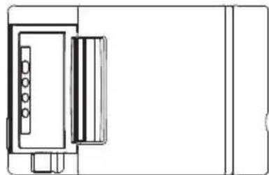
5.1 External Views and Dimensions
(Unit: mm)
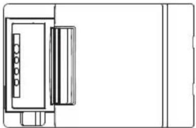
natural_image
Pure technical line drawing of a mechanical component without any text, numbers, or symbols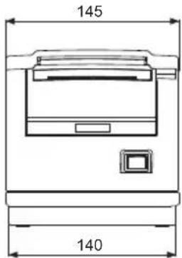
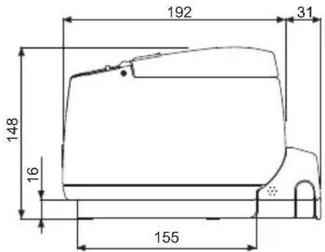
Built-in power supply type
natural_image
Pure technical line drawing of a mechanical component without any text, numbers, or symbols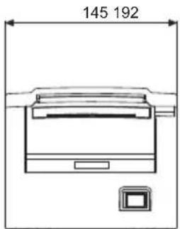

AC adapter type
5.2 Printing Paper
Use the paper shown in the following table or paper of the same quality.
| Paper type Product name | |
| Recommended thermal roll paper | TF50KS-E2D, TF50KS-E or TF60KS-E from Nippon PaperPD150R or PD160R from Ohji PaperP220AG, HP220A, HP220AB-1, F230AA, P220AB, or PB670(2-color paper) from Mitsubishi Paper |
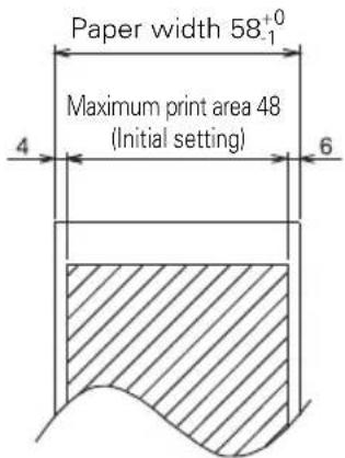
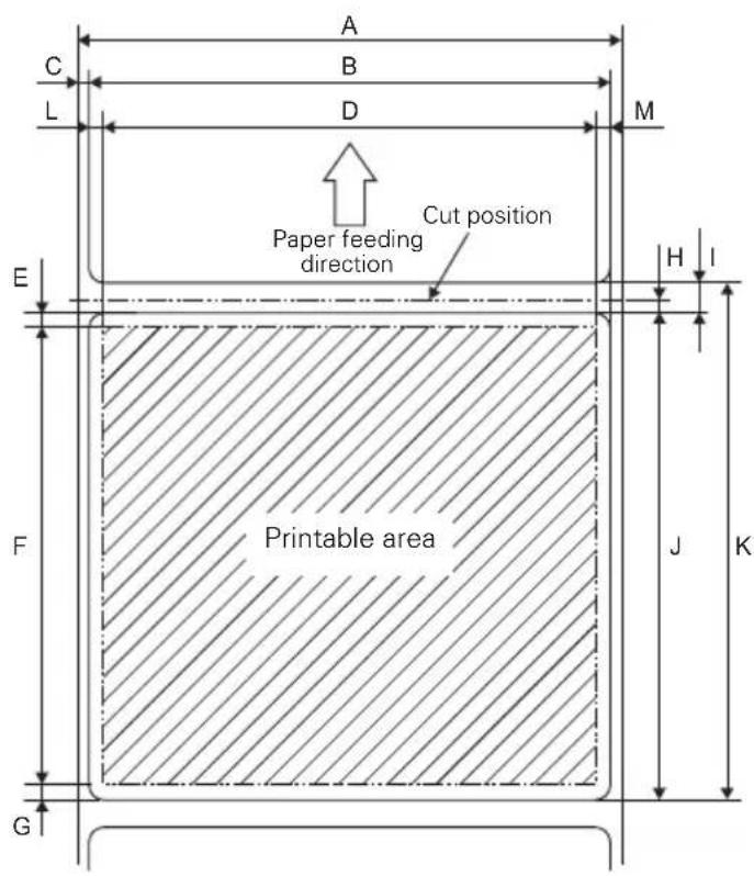
a) Thermal roll paper
(Unit: mm)
| Paper thickness (μm) | 53-75 75-85 |
| Core inner diameter d (mm) | 12 25.4 |
| Core outer diameter D (mm) | 18 32 |

CAUTION
Use thermal paper that is wound as follows:
■ Not creased and fits tight to the core.
■ Not folded.
■ Not glued to the core.
■ Rolled with the printable side out.
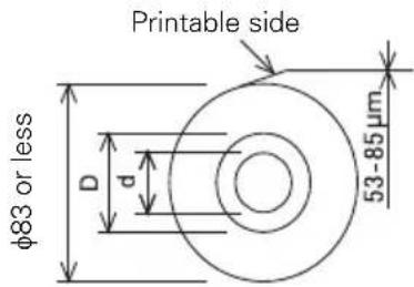
b) Label paper
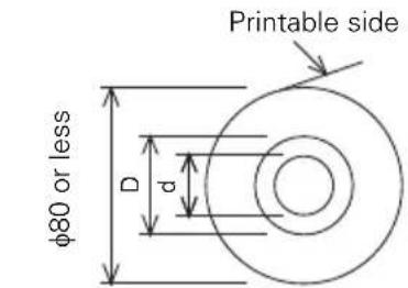
Roll paper specifications
| Label paper thickness (μm) 65 to 85 |
| Label backing thickness (μm) 60 or less |
| Core inner diameter d (mm) 25.4 |
| Core outer diameter D (mm) 32 |
(Unit: mm)
| Mark | Item Dimensions | |
| A Label backing width 57.5, 59.5 | 79.5,82.5 ± 0.5 | |
| B Label width (Size A) -4 ± 0.5 | ||
| C Left edge of label 2 ± 0.5 | ||
| D Print width (Size A) -8 | ||
| E Top margin 2 ± 1 | ||
| F | Print length | 21 to 296 |
| G Bottom margin 2 ± 1 | ||
| H | Cut position between labels | 1/2 x (Size I) |
| I | Gap between labels | 4 to 30 |
| J | Label length | 25 to 300 |
| K Label pitch I + J | ||
| L | Left margin | 2 ± 1 |
| M | Right margin | 2 ± 1 |

CAUTION
■ Note the following points when using the auto cutter. Ignoring this information can result in cutter lock or cutter malfunction.
- Make sure the paper cut length is at least 29 mm.
- Make sure the cut position is between labels. Cut the backing paper. Do not cut label paper (tack paper).
■ Always re-calibrate the paper sensor whenever you change the label backing paper type.
■ Make sure the left and right margins of the paper are at least 2 mm each.
c) Black mark paper
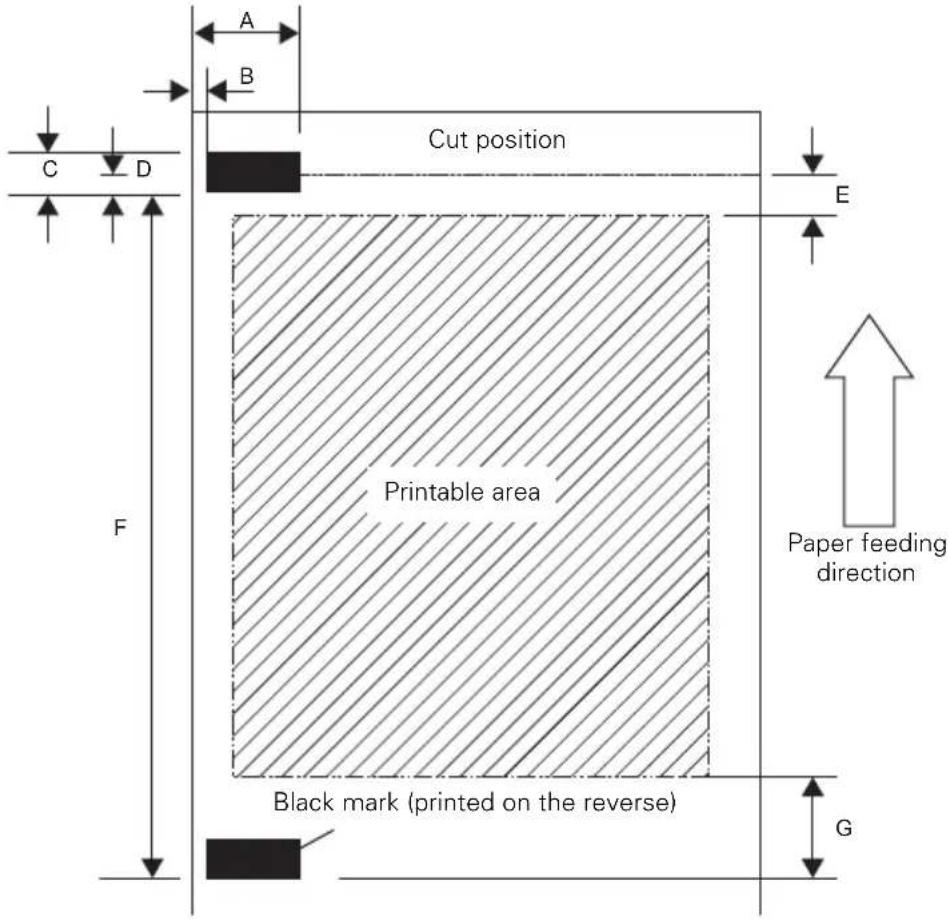
(Unit: mm)
| Mark Item | Dimensions | ||
| M1 M2* | |||
| A Right edge of black mark 13.4 or more | 79 or more | ||
| B Left edge of black mark 0.4 or less 67.7 | or less | ||
| C Black mark height 5 | |||
| D Cut position in black mark 2.5 | |||
| E | T o p m a r g | n 6 . 5 | |
| F | Black mark pitch | 30 to 300 | |
| G Bottom margin 9 | |||
Note:
*:3-inch type only

CAUTION
■ The black mark PCS value should be at least 0.90.
■ Concerning the accuracy of feeding with black mark detection, allow for an error of ±2 mm from the reference print position, or for a maximum error of -5% from the value set for the print length.
■ The print area is as shown in the illustration above when black marks are being used. Make sure to allow for adequate margins. The printer will perform a page skip operation if the print data runs outside of the print area.
■ When pre-printing on black mark paper, print outside of the area detected by the black mark sensor.
5.3 Manual Setting of Memory Switches
Memory switches are used to set various printer settings. The memory switches can be set manually (set by hand on the printer) or by commands. This section explains how to perform manual settings.
Memory switch settings are done in memory switch setting mode or virtual DIP switch setting mode. In the memory switch setting mode, you can set the values for MSW1 to MSW13. In the virtual DIP switch setting mode, you can set the values for MSW1 to MSW6.
For information on how to set the memory switches using commands, please refer to the Command Reference.
Outline of procedure
- Enter memory switch setting mode or virtual DIP switch setting mode.
- Change settings that need to be changed.
- Go to the save settings menu.
- Save settings.
Memory switch setting mode
While “Online” is displayed, press and hold button 4 (MENU) for at least two seconds. Or, while paper is loaded, press and hold button 3 and then turn on the power.
Enter memory switch setting mode.
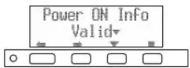
- Press button 1 ( ) or button 2 ( ) to select items to set.
- Press button 3 ( ) to select a value for the selected item.
- Press button 4 ( ) to go to the save settings menu.
● To set all the memory switches to the factory settings:
Press button 1 until "Factory Setting /Set" appears (after MSW13-6).
Press and hold button 4 for at least two seconds. All memory switches change to the factory settings.
Virtual DIP switch setting mode
While paper is loaded, press and hold button 2 while turning the power on. Enter virtual DIP switch setting mode.
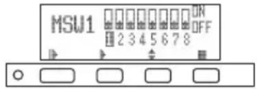
- Press button 1(▶) to select a memory switch number. (Switches cycle in the following order: MSW1 → MSW2 → ... → MSW6 → MSW1)
- Press button 2 (▶ to move from switch 1 towards switch 8. (The selection loops from 8 back to 1.)
- Press button 3 (to change between ON and OFF.
- Press button 4 ( ) to go to the save settings menu.
Save settings menu
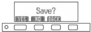
- Press button 1 (YES) to save the settings and return to the "Online" display.
- Press button 2 (NO) to not save the settings and return to the "Online" display.
- Press button 3 (BACK) to return to the previous mode.
The function of each memory switch is shown in the following table. (Shaded values are factory settings.)
| Switch no. | Function OFF ON | ||
| MSW1-1 | Power ON Info | Valid Not Send | |
| MSW1-2 | Buffer Size | 4K bytes 45 bytes | |
| MSW1-3 | Busy Condition | Full/Err Full | |
| MSW1-4 | Receive Error | Print"?" No Print | |
| MSW1-5 | CR Mode | Ignored | LF |
| MSW1-6 | Reserved | Fixed | — |
| MSW1-7 | DSR Signal | Invalid | Valid |
| MSW1-8 | Init Signal | Invalid | Valid |
| MSW2-1 | Reserved | — | Fixed |
| MSW2-2 | Auto Cutter | Invalid | Valid |
| *1 MSW2-3 | Spool Print | Invalid | Valid |
| MSW2-4 | Full Col Print | LineFeed | WaitData |
| MSW2-5 | Resume aft PE | Next | Top |
| MSW2-6 | Reserved | Fixed | — |
| MSW2-7 | Reserved | Fixed | — |
| MSW2-8 | PNE Sensor | Valid Invalid | |
| MSW3-1 | Resume Ctr Err | Valid Invalid | |
| MSW3-2 | PE signal by PNE | Valid | Invalid |
| MSW3-3 | Parallel 31 Pin | Valid Invalid | |
| MSW3-4 | Reserved | Fixed | — |
| MSW3-5 | Reserved | Fixed | — |
| MSW3-6 | Reserved | Fixed | — |
| MSW3-7 | CBM1000 Mode | Invalid | Valid |
| MSW3-8 | Resume Open Err | Close | Command |
| MSW4-1 | Reserved | Fixed | — |
| *2*3 MSW4-1 | PLength Set | Auto Measure | Command |
| MSW4-2 | Reserved | Fixed | — |
| *2*3 MSW4-2 | Power on TOF | Invalid | Valid |
| MSW4-3 | Feed&Cut at TOF | Invalid | Valid |
| *2*3 MSW4-3 | Feed&Cut at TOF | Invalid | Valid |
| MSW4-4 | Reserved | Fixed | — |
| *2*3 MSW4-4 | Paper Select | Thermal Roll | BM.P/Lbl.P |
| MSW4-5 | Reserved | Fixed | — |
| *2 MSW4-5 | Position Detect | Black Mark | Label |
| *3 MSW4-5 | Position Detect | Black Mark | Label |
| MSW4-6 | Reserved | Fixed | — |
| *2*3 MSW4-6 | Measure at close | Invalid | Valid |
| MSW4-7 | Reserved | Fixed | — |
| MSW4-8 | Partial Only | Invalid | Valid |
| MSW5-1 | Buzzer | Valid Invalid | |
| MSW5-2 | Line Pitch | 1/360 | 1/406 |
| Switch no. | Function | OFF | ON |
| MSW5-3 USB Mode Virtual COM Printer Class | |||
| MSW5-4 Reserved | Fixed — | ||
| MSW5-5 GradationQuality | Quality Speed | ||
| MSW5-6 Reserved | Fixed — | ||
| MSW5-7 Reserved | Fixed — | ||
| MSW5-8 Reserved | Fixed — | ||
| MSW6-1 Act. For Driver | Invalid Valid | ||
| MSW6-2 Character Space | Invalid Valid | ||
| MSW6-3 USB Power Save | Invalid Valid | ||
| MSW6-4 Reserved | Fixed — | ||
| MSW6-5 Reserved | Fixed — | ||
| MSW6-6 Reserved | Fixed — | ||
| MSW6-7 Reserved | Fixed — | ||
| MSW6-8 Reserved | Fixed — | ||
| Switch no. | Function Initial setting | Setting value | |
| *4 MSW7-1 | Baud Rate | 9600 bps | 1200 bps, 2400 bps, 4800 bps, 9600 bps, 19200 bps, 38400 bps, 57600 bps, 115200 bps |
| *4 MSW7-2 | Data Length | 8bits | 7bits, 8bits |
| MSW7-3 | Stop Bit | 1bit | 1bit, 2bits |
| *4 MSW7-4 | Parity | NONE | NONE, EVEN, ODD |
| *4 MSW7-5 | Flow Control | DTR/DSR | DTR/DSR, XON/XOFF |
| MSW7-6 | DMA Control | Valid | Valid, Invalid |
| MSW7-7 | VCom Protocol | PC Setting | PC Setting, DTR/DSR, XON/XOFF |
| MSW8-1 | Print Width | 576dots(3-inch type)384dots(2-inch type) | 640 dots, 576 dots, 546 dots, 512 dots, 436 dots, 432 dots, 420 dots, 390 dots, 384 dots, 360 dots |
| MSW8-2 | Paper Type | 1 Color Normal | 1 Color Normal, 2 Color Normal |
| MSW8-3 | Top Margin | 11mm | 3mm, 4mm, 5mm, 6mm, 7mm, 8mm, 9mm, 10mm, 11mm |
| MSW8-4 | Line Gap Reduce | Invalid | Invalid, 3/4, 2/3, 1/2, 1/3, 1/4, 1/5, ALL |
| MSW8-5 | Reduced Char V/H | 100% / 100% | 100% / 100%, 75% / 100%, 50% / 100%, 100% / 75%, 75% / 75%, 50% / 75% |
| MSW8-6 | Auto Side Shift | Invalid | Invalid, 1 dots, 2 dots, 3 dots, 4 dots, 5 dots, 6 dots, 7 dots |
| MSW8-7 | Liner Free Mode | Invalid | Invalid, 1h, 6h, 12h, 18h, 24h, 5m, 10m, 15m, 20m, 30m |
| MSW9-1 | Code Page | PC 437 | PC 437, Katakana, PC 850,858, PC 860, PC 863, PC 865, PC 852, PC 866, PC 857, WPC1252, Space page, PC 864, ThaiCode11 1Pass, ThaiCode11 3Pass, ThaiCode18 1Pass, ThaiCode18 3Pass, TCVN-3 |
| MSW9-2 | Int'Char Set | USA | USA, France, Germany, England, Denmark, Sweden, Italy, Spain, Japan, Norway, Denmark 2, Spain 2, Latin America, Korea, Croatia, China, Vietnam |
| Switch no. | Function | Initial setting | Setting value |
| MSW9-4 Multi-byte Char | Invalid JIS | JPN), SJIS:CP932 (JPN), SJIS:X0213(JPN), GB18030(CHN), KS Hangul(KOR), EUC Hangul(KOR), BIG5(TWN), Invalid | |
| MSW9-6 LCD Language | English English | English, Français, Deutsch, Italiano, Español, Japanese, Chinese | |
| MSW9-7 LCD Ext Char | Valid Invalid, Valid | ||
| MSW9-8 LCD Auto Off | Never Never, 30seconds, 5minutes | ||
| MSW10-1 Print Density | 100 % 70 %, 75 %, 80 %, 85 %, 90 %, 95 %, 100 %, 105 %, 110 %, 115 %, 120 %, 125 %, 130 %, 135 %, 140 % | ||
| MSW10-2 Print Speed | Level 9 | Level 1, Level 2, Level 3, Level 4, Level 5, Level 6, Level 7, Level 8, Level 9 | |
| MSW10-3 ACK Timing | Before Busy | Before Busy, Same Period, After Busy | |
| MSW10-4 | Old command | Invalid Invalid, CBM1, CBM2 | |
| MSW10-5 Buzzer Event | Not by C.Open | All Event/Error, Not by C.Open, Not by C.Open/PE | |
| MSW10-6 | Buzzer Sound | Tone 2 | Tone 1, Tone 2, Tone 3, Tone 4 |
| MSW10-7 | Key Lock | Invalid Invalid, Valid | |
| MSW10-8 | LCD Direction | Normal Normal, Inverted | |
| MSW13-1 Security/Target | Low/All | Low/All, Mid/All, Mid/Paired only, Hi/All, Hi/Paired only | |
| MSW13-5 | BT Device Scan | Discoverable | No Response, Discoverable |
| MSW13-6 | Auto Reconnect | Valid Invalid, Valid | |
Notes:
*1: If print data is very dense, the print head is hot, data transmission is slow, or some other conditions, the motor and printing may occasionally stop which causes white stripes in the printout. To print high-density data, set MSW2-3 (Spool Print) to ON to reduce striping, although this increases the time before printing starts.
For a serial interface, increase the transmission speed to prevent the motor from stopping.
*2: Label printing
*3: Black mark model
*4: The values for memory switches MSW7-X are only effective when DIP switch no. 1 is set to OFF.
FRANÇAIS
PRÉCAUTIONS GÉNÉRALES
"Made for iPod," "Made for iPhone," and "Made for iPad" mean that an electronic accessory has been designed to connect specifically to iPod, iPhone, or iPad, respectively, and has been certified by the developer to meet Apple performance standards. Apple is not responsible for the operation of this device or its compliance with safety and regulatory standards.
Please note that the use of this accessory with iPod, iPhone or iPad may affect wireless performance.
- iPad, iPhone and iPod touch are trademarks of Apple Inc., registered in the U.S. and other countries. iPad Air and iPad mini are trademarks of Apple Inc.
● EPSON and ESC/POS are registered trademarks of Seiko Epson Corporation. - QR Code is a registered trademark of DENSO WAVE INCORPORATED.
- Ethernet is a registered trademark of Fuji Xerox Corporation.
- Bluetooth® is a registered trademark of Bluetooth-SIG Inc.
● CITIZEN is a registered trademark of Citizen Watch Co., Ltd. Japan
● All other trademarks are the property of their respective owners. - Citizen Systems use these trademarks in accordance with the license of relevant owners.
PRÉCAUTIONS DE SÉCURITÉ...QUI DEVRAIENT ÊTRE OBSERVÉES RIGOUREUSEMENT
CETTE ÉTIQUETTE SIGNALE LE RISQUE DE BRÛLURES LIÉES À LA TEMPÉRATURE ÉLEVÉE DE LA TÊTE D'IMPRESSION ET LE RISQUE DE COUPURES OCCASIONNÉES PAR LES MÉCANISMES DE DÉCOUPE MANUELS ET AUTOMATIQUES LORSQUE LE CAPOT DU PAPIER EST OUVERT.
natural_image
Line drawing of a mechanical device with no visible text or symbols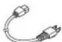

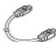
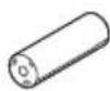

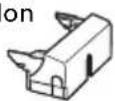
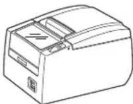
natural_image
Line drawing of a rectangular electronic device with ports and a lid (no text or symbols)natural_image
Technical line drawing of a connector assembly with a USB cable and connector pin (no text or symbols)Interface série
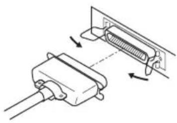
natural_image
Technical line drawing of a mechanical component with directional arrows indicating assembly or movement (no text or symbols)Interface parallèle
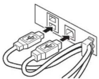
natural_image
Diagram of two USB connectors connected to a power outlet (no text or symbols)natural_image
Simple line drawing of a cable connector inserted into a socket (no text or symbols)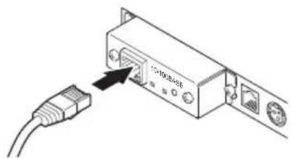
Interface Ethernet Interface Powered USB
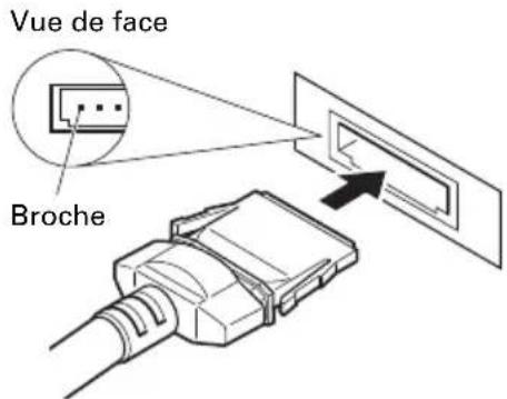
natural_image
Diagram of a cable connector with an attached port, showing no text or symbolsBluetooth + USB
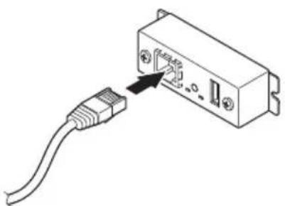
natural_image
Diagram of a USB cable inserted into an electronic device (no text or symbols visible)LAN sans fil + LAN

ATTENTION
| Signal | Broche | Broche | Signal | |
| FG | 1 1 FG | |||
| TXD | 2 2 TXD | |||
| RXD | 3 3 RXD | |||
| CTS | 5 4 RTS | |||
| DSR | 6 6 DSR | |||
| SG | 7 7 SG | |||
| DTR | 20 | 20 | DTR |
Câble 9 broches - 25 broches
| Ordinateur | Imprimante | ||
| Signal | Broche Broche | Signal | |
| RXD 2 | TXD | ||
| TXD 3 | RXD | ||
| DTR 4 | RTS | ||
| SG 5 | DSR | ||
| DSR 6 | SG | ||
| CTS 8 | 20 | DTR | |

ATTENTION
natural_image
Pure electrical circuit lines without any symbolsPrint server homepage
Menu
Print server configuration
Printer status
LAN I/F information
Copyright (C) 2010 CITIZEN SYSTEMS JAPAN CO.,LTD. All Rights reserved.
natural_image
Diagram of a device rear panel with ports and connectors (no text or labels)natural_image
Line drawing of a mechanical device with no visible text or symbolsPosition horizontale
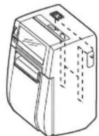
natural_image
Line drawing of a mechanical device with no visible text or symbolsInstallation au mur
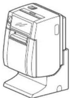
natural_image
Line drawing of a mechanical device with no visible text or symbolsPosition verticale

Remarques:
*1: Type 2 pouces (58/60 mm)
*2: Type 3 pouces (80/83 mm)

ATTENTION
natural_image
Line drawing of a mechanical device with a button and mounting bracket (no text or symbols)natural_image
Technical line drawing of two electronic devices with internal components and wiring (no text or symbols)CT-S801IIS
CT-S801IIS
natural_image
Technical line drawing of a mechanical component or bracket (no text or symbols)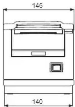

natural_image
Pure technical line drawing of a mechanical component without any text, numbers, or symbols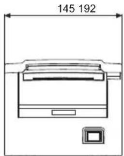
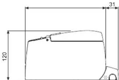
"Made for iPod," "Made for iPhone," and "Made for iPad" mean that an electronic accessory has been designed to connect specifically to iPod, iPhone, or iPad, respectively, and has been certified by the developer to meet Apple performance standards. Apple is not responsible for the operation of this device or its compliance with safety and regulatory standards.
Please note that the use of this accessory with iPod, iPhone or iPad may affect wireless performance.
- iPad, iPhone and iPod touch are trademarks of Apple Inc., registered in the U.S. and other countries. iPad Air and iPad mini are trademarks of Apple Inc.
- EPSON and ESC/POS are registered trademarks of Seiko Epson Corporation.
- QR Code is a registered trademark of DENSO WAVE INCORPORATED.
- Ethernet is a registered trademark of Fuji Xerox Corporation.
- Bluetooth® is a registered trademark of Bluetooth-SIG Inc.
● CITIZEN is a registered trademark of Citizen Watch Co., Ltd. Japan
● All other trademarks are the property of their respective owners. - Citizen Systems use these trademarks in accordance with the license of relevant owners.
natural_image
Technical line drawing of a mechanical device with no visible text or symbols

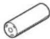
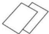
natural_image
Line drawing of a rectangular electronic device with ports and a lid (no text or symbols)WF: WiFi W5: WiFi (5,0 GHz)
natural_image
Technical line drawing of a connector assembly with a USB cable and connector pin (no text or symbols)natural_image
Technical line drawing of a mechanical component with directional arrows indicating assembly or movement (no text or symbols)natural_image
Diagram of two USB connectors connected to a power outlet (no text or symbols)natural_image
Simple line drawing of a cable connector inserted into a socket (no text or symbols)Vorderansicht
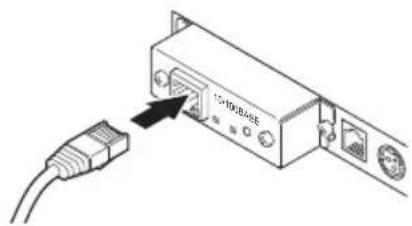
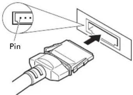
natural_image
Diagram of an electronic device showing a cable inserted into a port with an attached USB symbol (no text or labels present)Bluetooth + USB
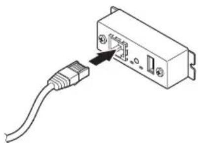
natural_image
Diagram of a USB cable connector with an attached switch (no text or symbols)WLAN + LAN

VORSICHT
| Signal | Pin Pin | Signal | |
| FG | 1 1 FG | ||
| TXD | 2 2 TXD | ||
| RXD | 3 3 RXD | ||
| CTS | 5 4 RTS | ||
| DSR | 6 6 DSR | ||
| SG | 7 7 SG | ||
| DTR | 20 | 20 DTR |
PC
| Signal | Pin Pin | Signal | |
| RXD 2 | TXD | ||
| TXD 3 | RXD | ||
| DTR 4 | RTS | ||
| SG 5 | DSR | ||
| DSR 6 | SG | ||
| CTS 8 | 20 DTR |

VORSICHT
natural_image
Pure electrical circuit lines without any symbolsStatus-LED Schalter
Print server homepage
Menu
Print server configuration
Printer status
LAN I/F information
Copyright (C) 2010 CITIZEN SYSTEMS JAPAN CO.,LTD. All Rights reserved.
natural_image
Line drawing of a mechanical device with no visible text or symbolsnatural_image
Line drawing of a mechanical device with no visible text or symbolsWandmontage
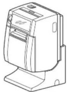
natural_image
Line drawing of a mechanical device with no visible text or symbols
natural_image
Technical line drawing of a mechanical device with an open lid and internal compartments (no text or symbols)
VORSICHT
natural_image
Line drawing of a mechanical device with a button and mounting bracket (no text or symbols)natural_image
Technical line drawing of two views of a device showing internal components and wiring (no text or symbols)CT-S801IIS
CT-S801IIS
natural_image
Technical line drawing of a mechanical component or bracket (no text or symbols)
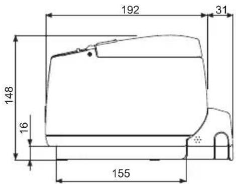
natural_image
Pure technical line drawing of a mechanical component without any text, numbers, or symbols
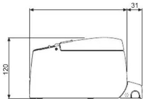
"Made for iPod," "Made for iPhone," and "Made for iPad" mean that an electronic accessory has been designed to connect specifically to iPod, iPhone, or iPad, respectively, and has been certified by the developer to meet Apple performance standards. Apple is not responsible for the operation of this device or its compliance with safety and regulatory standards.
Please note that the use of this accessory with iPod, iPhone or iPad may affect wireless performance.
- iPad, iPhone and iPod touch are trademarks of Apple Inc., registered in the U.S. and other countries. iPad Air and iPad mini are trademarks of Apple Inc.
● EPSON and ESC/POS are registered trademarks of Seiko Epson Corporation. - QR Code is a registered trademark of DENSO WAVE INCORPORATED.
- Ethernet is a registered trademark of Fuji Xerox Corporation.
- Bluetooth® is a registered trademark of Bluetooth-SIG Inc.
● CITIZEN is a registered trademark of Citizen Watch Co., Ltd. Japan
● All other trademarks are the property of their respective owners. - Citizen Systems use these trademarks in accordance with the license of relevant owners.
PRECAUZIONI DI SICUREZZA ..DA OSSERVARE RIGOROSAMENTE
QUESTA ETICHETTA INDICA IL RISCHIO DI USTIONE PER VIA DELLE ALTE TEMPERATURE PRESENTI SULLA TESTINA DI STAMPA E IL RISCHIO DI FERIRSI CON LA TAGLIERINA MANUALE E AUTOMATICA QUANDO IL COPERCHIO DELLA CARTA È APERTO.
natural_image
Line drawing of a mechanical device with no visible text or symbolsnatural_image
Line drawing of a portable electronic device with ports and buttons (no text or symbols)WF: WiFi W5: WiFi(5.0GHz)
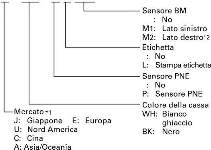
natural_image
Technical line drawing of a connector assembly with a USB cable and two connectors (no text or symbols)Interfaccia seriale
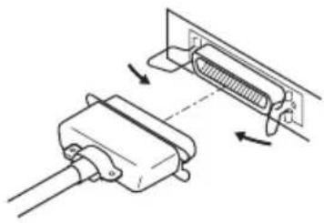
natural_image
Technical line drawing of a mechanical component with arrows indicating assembly or movement (no text or symbols)natural_image
Diagram of two USB connectors connected to a power outlet (no text or symbols)natural_image
Diagram of a cable connector inserted into a socket, showing wiring and mounting bracket (no text or symbols)Vista anteriore

Interfaccia Ethernet
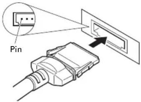
Interfaccia Powered USB

natural_image
Diagram of a device with an attached cable and connector (no text or symbols)Bluetooth + USB

natural_image
Diagram of a USB cable connector with an attached switch (no text or symbols)Wireless LAN + LAN

ATTENZIONE
natural_image
Pure electrical circuit lines without any symbolsPrint server homepage
Menu
Print server configuration
Printer status
LAN I/F information
Copyright (C) 2010 CITIZEN SYSTEMS JAPAN CO.,LTD. All Rights reserved.
natural_image
Line drawing of a mechanical device with no visible text or symbolsnatural_image
Line drawing of a mechanical device with no visible text or symbolsnatural_image
Line drawing of a mechanical device with no visible text or symbolsPosizione verticale
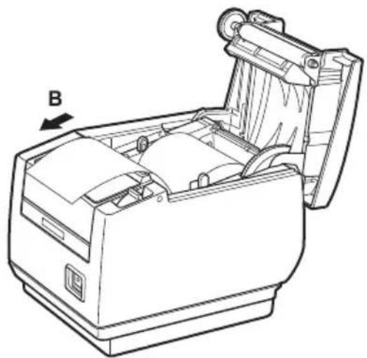
natural_image
Technical line drawing of a mechanical device with an open lid and internal components, labeled with 'B' and no visible text or symbols.
ATTENZIONE
natural_image
Line drawing of a device casing with a button and indicator lights (no text or symbols)natural_image
Technical line drawing of two views of a device showing internal components and wiring (no text or symbols)CT-S801IIS
CT-S801IIS
natural_image
Technical line drawing of a mechanical component or housing (no text or symbols)

natural_image
Pure technical line drawing of a mechanical component without any text, numbers, or symbols

| N. switch Funzione OFF ON | |||
| MSW1-1 Power ON Info | Valid Not Send | ||
| MSW1-2 Buffer Size | 4K bytes 45 bytes | ||
| MSW1-3 Busy Condition | Full/Err Full | ||
| MSW1-4 Receive Error | Print"?" No Print | ||
| MSW1-5 CR Mode | Ignored | LF | |
| MSW1-6 Reserved | Fixed | — | |
| MSW1-7 | DSR Signal | Invalid | Valid |
| MSW1-8 | Init Signal | Invalid | Valid |
| MSW2-1 Reserved | — | Fixed | |
| MSW2-2 | Auto Cutter | Invalid | Valid |
| *1 MSW2-3 | Spool Print | Invalid | Valid |
| MSW2-4 | Full Col Print | LineFeed | WaitData |
| MSW2-5 | Resume aft PE | Next | Top |
| MSW2-6 Reserved | Fixed | — | |
| MSW2-7 Reserved | Fixed | — | |
| MSW2-8 | PNE Sensor | Valid | Invalid |
| MSW3-1 | Resume Ctr Err | Valid | Invalid |
| MSW3-2 | PE signal by PNE | Valid | Invalid |
| MSW3-3 | Parallel 31 Pin | Valid | Invalid |
| MSW3-4 Reserved | Fixed | — | |
| MSW3-5 Reserved | Fixed | — | |
| MSW3-6 Reserved | Fixed | — | |
| MSW3-7 | CBM1000 Mode | Invalid | Valid |
| MSW3-8 | Resume Open Err | Close | Command |
| MSW4-1 Reserved | Fixed | — | |
| *2*3 MSW4-1 | P.Length Set | Auto Measure | Command |
| MSW4-2 Reserved | Fixed | — | |
| *2*3 MSW4-2 | Power on TOF | Invalid | Valid |
| MSW4-3 | Feed&Cut at TOF | Invalid | Valid |
| *2*3 MSW4-3 | Feed&Cut at TOF | Invalid | Valid |
| MSW4-4 Reserved | Fixed | — | |
| *2*3 MSW4-4 | Paper Select Thermal Roll BM.P/Lbl.P | ||
| MSW4-5 Reserved | Fixed | — | |
| *2 MSW4-5 | Position Detect | Black Mark | Label |
| *3 MSW4-5 | Position Detect | Black Mark | Label |
| MSW4-6 Reserved | Fixed | — | |
| *2*3 MSW4-6 | Measure at close | Invalid | Valid |
| MSW4-7 Reserved | Fixed | — | |
| MSW4-8 | Partial Only | Invalid | Valid |
| MSW5-1 | Buzzer | Valid | Invalid |
| MSW5-2 | Line Pitch | 1/360 1/406 | |
| N. switch | Funzione | OFF | ON |
| MSW5-3 UB Mode Virtual COM Printer Class | |||
| MSW5-4 Reserved | Fixed — | ||
| MSW5-5 GradationQuality | Quality Speed | ||
| MSW5-6 Reserved | Fixed — | ||
| MSW5-7 Reserved | Fixed — | ||
| MSW5-8 Reserved | Fixed — | ||
| MSW6-1 Act. For Driver | Invalid Valid | ||
| MSW6-2 Character Space | Invalid Valid | ||
| MSW6-3 UB Power Save | Invalid Valid | ||
| MSW6-4 Reserved | Fixed — | ||
| MSW6-5 Reserved | Fixed — | ||
| MSW6-6 Reserved | Fixed — | ||
| MSW6-7 Reserved | Fixed — | ||
| MSW6-8 Reserved | Fixed — | ||
| N. switch Funzione | Impostazione iniziale | Valore impostato | |
| *4MSW7-1 | Baud Rate | 9600 bps | 1200 bps, 2400 bps, 4800 bps, 9600 bps, 19200 bps, 38400 bps, 57600 bps, 115200 bps |
| *4MSW7-2 | Data Length | 8bits | 7bits, 8bits |
| MSW7-3 | Stop Bit | 1bit | 1bit, 2bits |
| *4MSW7-4 | Parity | NONE | NONE, EVEN, ODD |
| *4MSW7-5 | Flow Control | DTR/DSR | DTR/DSR, XON/XOFF |
| MSW7-6 | DMA Control | Valid | Valid, Invalid |
| MSW7-7 | VCom Protocol | PC Setting | PC Setting, DTR/DSR, XON/XOFF |
| MSW8-1 | Print Width | 576dots(Tipo da 3 pollici)384dots(Tipo da 2 pollici) | 640 dots, 576 dots, 546 dots, 512 dots, 436 dots, 432 dots, 420 dots, 390 dots, 384 dots, 360 dots |
| MSW8-2 | Paper Type | 1 Color Normal | 1 Color Normal, 2 Color Normal |
| MSW8-3 | Top Margin | 11mm | 3mm, 4mm, 5mm, 6mm, 7mm, 8mm, 9mm, 10mm, 11mm |
| MSW8-4 | Line Gap Reduce | Invalid | Invalid, 3/4, 2/3, 1/2, 1/3, 1/4, 1/5, ALL |
| MSW8-5 | Reduced Char V/H | 100% / 100% | 100% / 100%, 75% / 100%, 50% / 100%, 100% / 75%, 75% / 75%, 50% / 75% |
| MSW8-6 | Auto Side Shift | Invalid | Invalid, 1 dots, 2 dots, 3 dots, 4 dots, 5 dots, 6 dots, 7 dots |
| MSW8-7 | Liner Free Mode | Invalid | Invalid, 1h, 6h, 12h, 18h, 24h, 5m, 10m, 15m, 20m, 30m |
| MSW9-1 | Code Page | PC 437 | PC 437, Katakana, PC 850,858, PC 860, PC 863, PC 865, PC 852, PC 866, PC 857, WPC1252, Space page, PC 864, ThaiCode11 1Pass, ThaiCode11 3Pass, ThaiCode18 1Pass, ThaiCode18 3Pass, TCVN-3 |
| N. switch | Funzione | Impostazione iniziale | Valore impostato |
| MSW9-2 Int'Char Set | USA USA | France, Germany, England, Denmark, Sweden, Italy, Spain, Japan, Norway, Denmark 2, Spain 2, Latin America, Korea, Croatia, China, Vietnam | |
| MSW9-4 Multi-byte Char | Invalid JIS(JPN), SJIS:CP932 (JPN), SJIS:X0213(JPN), GB18030(CHN), KS Hangul(KOR), EUC Hangul(KOR), BIG5(TWN), Invalid | ||
| MSW9-6 LCD Language | English | English, Français, Deutsch, Italiano, Español, Japanese, Chinese | |
| MSW9-7 LCD Ext Char | Valid Invalid, Valid | ||
| MSW9-8 LCD Auto Off | Never Never, 30seconds, 5minutes | ||
| MSW10-1 Print Density | 100 % | 70 %, 75 %, 80 %, 85 %, 90 %, 95 %, 100 %, 105 %, 110 %, 115 %, 120 %, 125 %, 130 %, 135 %, 140 % | |
| MSW10-2 Print Speed | Level 9 | Level 1, Level 2, Level 3, Level 4, Level 5, Level 6, Level 7, Level 8, Level 9 | |
| MSW10-3 | ACK Timing | Before Busy | Before Busy, Same Period, After Busy |
| MSW10-4 Old command | Invalid Invalid, CBM1, CBM2 | ||
| MSW10-5 Buzzer Event | Not by C.Open | All Event/Error, Not by C.Open, Not by C.Open/PE | |
| MSW10-6 Buzzer Sound | Tone 2 | Tone 1, Tone 2, Tone 3, Tone 4 | |
| MSW10-7 | Key Lock | Invalid Invalid, Valid | |
| MSW10-8 LCD Direction | Normal Normal, Inverted | ||
| MSW13-1 Security/Target | Low/All Low/All, Mid/All, Mid/Paired only, Hi/All, Hi/Paired only | ||
| MSW13-5 BT Device Scan | Discoverable | No Response, Discoverable | |
| MSW13-6 | Auto Reconnect | Valid Invalid, Valid | |
"Made for iPod," "Made for iPhone," and "Made for iPad" mean that an electronic accessory has been designed to connect specifically to iPod, iPhone, or iPad, respectively, and has been certified by the developer to meet Apple performance standards. Apple is not responsible for the operation of this device or its compliance with safety and regulatory standards.
Please note that the use of this accessory with iPod, iPhone or iPad may affect wireless performance.
- iPad, iPhone and iPod touch are trademarks of Apple Inc., registered in the U.S. and other countries. iPad Air and iPad mini are trademarks of Apple Inc.
● EPSON and ESC/POS are registered trademarks of Seiko Epson Corporation. - QR Code is a registered trademark of DENSO WAVE INCORPORATED.
- Ethernet is a registered trademark of Fuji Xerox Corporation.
- Bluetooth® is a registered trademark of Bluetooth-SIG Inc.
● CITIZEN is a registered trademark of Citizen Watch Co., Ltd. Japan
● All other trademarks are the property of their respective owners. - Citizen Systems use these trademarks in accordance with the license of relevant owners.
NORMAS DE SEGURIDAD..QUE DEBEN SER SEGUIDAS ESTRICTAMENTE
ESTA ETIQUETA INDICA QUE EXISTE RIESGO DE SUFRIR QUEMADURAS DEBIDO A LAS ALTAS TEMPERATURAS DEL CABEZAL DE IMPRESIÓN, ASÍ COMO RIESGO DE SUFRIR CORTES POR LAS CIZALLAS MANUALES Y AUTOMÁTICAS MIENTRAS LA TAPA DEL PAPEL ESTÁ ABIERTA.
natural_image
Line drawing of a mechanical device with no visible text or symbolsnatural_image
Line drawing of a rectangular electronic device with ports and a lid (no text or symbols)WF: WiFi W5: WiFi (5,0GHz)
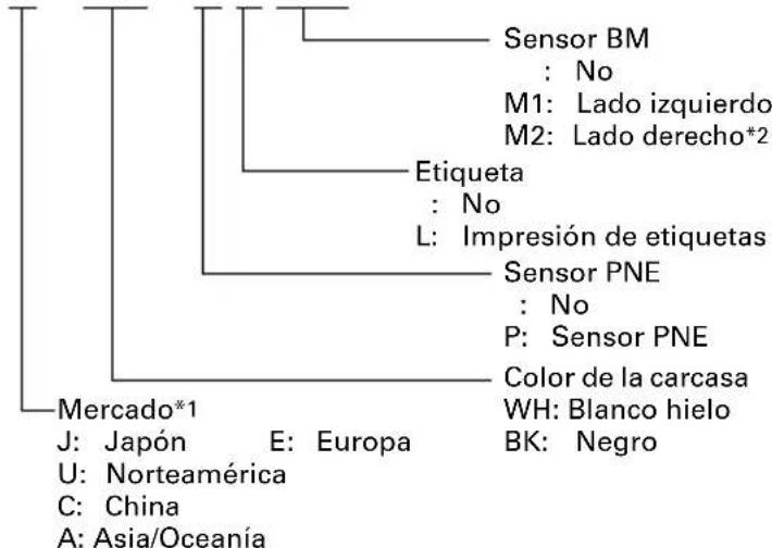
flowchart
graph TD
    A["Sensor BM<br>: No<br>M1: Lado izquierdo<br>M2: Lado derecho*2"] --> B["Etiqueta<br>: No<br>L: Impresión de etiquetas"]
    B --> C["Sensor PNE<br>: No<br>P: Sensor PNE"]
    C --> D["Color de la carcasa<br>WH: Blanco hielo<br>BK: Negro"]
    A --> E["Mercado*1<br>J: Japón E: Europa<br>U: Norteamérica<br>C: China<br>A: Asia/Oceania"]
natural_image
Technical line drawing of a connector assembly with a USB cable and two connected ports (no text or symbols)Interfaz serie

natural_image
Technical line drawing of a mechanical component with arrows indicating assembly or movement (no text or symbols)Interfaz paralelo
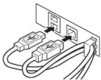
natural_image
Diagram of two USB connectors connected to a power outlet (no text or symbols)natural_image
Simple line drawing of a cable connector inserted into a socket (no text or symbols)Vista frontal

Interfaz Ethernet Interfaz Powered USB

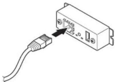
natural_image
Diagram of a USB cable connector with an attached switch (no text or symbols)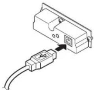
natural_image
Diagram of a device with an attached cable and connector (no text or symbols)Bluetooth + USB
LAN inalámbrica + LAN

PRECAUCION
natural_image
Pure electrical circuit lines without any symbolsInterruptoreLED de estado
Print server homepage
Menu
Print server configuration
Printer status
LAN I/F information
Copyright (C) 2010 CITIZEN SYSTEMS JAPAN CO.,LTD. All Rights reserved.
Conector applicable: TM3P-66P (Hirose) o equivalente
natural_image
Line drawing of a mechanical device with no visible text or symbolsPosición horizontal
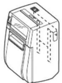
natural_image
Line drawing of a mechanical device with no visible text or symbolsInstalación mural

natural_image
Line drawing of a mechanical device with no visible text or symbolsPosición vertical
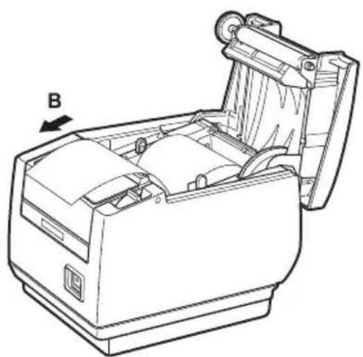
natural_image
Technical line drawing of a mechanical device with an open lid and internal components, labeled with 'B' and an arrow (no text or symbols beyond label)
PRECAUCION
natural_image
Line drawing of a mechanical device with a button and mounting bracket (no text or symbols)natural_image
Technical line drawing of a mechanical device with internal components and a directional arrow indicating rotation (no text or symbols)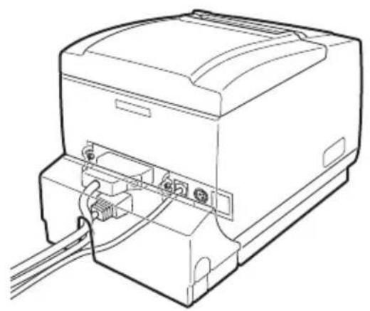
natural_image
Line drawing of a computer monitor with cables and connectors (no text or symbols)CT-S801IIS
CT-S801IIS
natural_image
Technical line drawing of a mechanical component or bracket (no text or symbols)
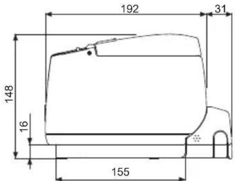
natural_image
Pure technical line drawing of a mechanical component without any text, numbers, or symbols

| N° de interruptor | Función OFF ON | ||
| MSW1-1 Power ON Info | Valid Not Send | ||
| MSW1-2 Buffer Size | 4K bytes 45 bytes | ||
| MSW1-3 Busy Condition | Full/Err Full | ||
| MSW1-4 Receive Error | Print“?” No Print | ||
| MSW1-5 CR Mode | Ignored | LF | |
| MSW1-6 Reserved | Fixed | — | |
| MSW1-7 | DSR Signal | Invalid | Valid |
| MSW1-8 | Init Signal | Invalid | Valid |
| MSW2-1 Reserved | — | Fixed | |
| MSW2-2 | Auto Cutter | Invalid | Valid |
| *1 MSW2-3 | Spool Print | Invalid | Valid |
| MSW2-4 | Full Col Print | LineFeed | WaitData |
| MSW2-5 | Resume aft PE | Next | Top |
| MSW2-6 Reserved | Fixed | — | |
| MSW2-7 Reserved | Fixed | — | |
| MSW2-8 | PNE Sensor | Valid | Invalid |
| MSW3-1 | Resume Ctr Err | Valid | Invalid |
| MSW3-2 | PE signal by PNE | Valid | Invalid |
| MSW3-3 | Parallel 31 Pin | Valid | Invalid |
| MSW3-4 Reserved | Fixed | — | |
| MSW3-5 Reserved | Fixed | — | |
| MSW3-6 Reserved | Fixed | — | |
| MSW3-7 | CBM1000 Mode | Invalid | Valid |
| MSW3-8 | Resume Open Err | Close | Command |
| MSW4-1 Reserved | Fixed | — | |
| *2*3 MSW4-1 | P.Length Set | Auto Measure | Command |
| MSW4-2 Reserved | Fixed | — | |
| *2*3 MSW4-2 | Power on TOF | Invalid | Valid |
| MSW4-3 | Feed&Cut at TOF | Invalid | Valid |
| *2*3 MSW4-3 | Feed&Cut at TOF | Invalid | Valid |
| MSW4-4 Reserved | Fixed | — | |
| *2*3 MSW4-4 | Paper Select | Thermal Roll | BM.P/Lbl.P |
| MSW4-5 Reserved | Fixed | — | |
| *2 MSW4-5 | Position Detect | Black Mark | Label |
| *3 MSW4-5 | Position Detect | Black Mark | Label |
| MSW4-6 Reserved | Fixed | — | |
| *2*3 MSW4-6 | Measure at close | Invalid | Valid |
| MSW4-7 Reserved | Fixed | — | |
| MSW4-8 Partial Only Invalid | Valid | ||
| MSW5-1 | Buzzer | Valid | Invalid |
| MSW5-2 | Line Pitch | 1/360 1/406 | |
| N° de interruptor | Función | OFF | ON |
| MSW5-3 UB Mode Virtual COM Printer Class | |||
| MSW5-4 Reserved | Fixed — | ||
| MSW5-5 GradationQuality | Quality Speed | ||
| MSW5-6 Reserved | Fixed — | ||
| MSW5-7 Reserved | Fixed — | ||
| MSW5-8 Reserved | Fixed — | ||
| MSW6-1 Act. For Driver | Invalid Valid | ||
| MSW6-2 Character Space | Invalid Valid | ||
| MSW6-3 UB Power Save | Invalid Valid | ||
| MSW6-4 Reserved | Fixed — | ||
| MSW6-5 Reserved | Fixed — | ||
| MSW6-6 Reserved | Fixed — | ||
| MSW6-7 Reserved | Fixed — | ||
| MSW6-8 Reserved | Fixed — | ||
| N° de interruptor | Función | Valor inicial | Valor de configuración |
| *4MSW7-1 | Baud Rate | 9600 bps | 1200 bps, 2400 bps, 4800 bps, 9600 bps, 19200 bps, 38400 bps, 57600 bps, 115200 bps |
| *4MSW7-2 | Data Length | 8bits | 7bits, 8bits |
| MSW7-3 | Stop Bit | 1bit | 1bit, 2bits |
| *4MSW7-4 | Parity | NONE | NONE, EVEN, ODD |
| *4MSW7-5 | Flow Control | DTR/DSR | DTR/DSR, XON/XOFF |
| MSW7-6 | DMA Control | Valid | Valid, Invalid |
| MSW7-7 | VCom Protocol | PC Setting | PC Setting, DTR/DSR, XON/XOFF |
| MSW8-1 | Print Width | 576dots(Tipo de 3 pulgadas)384dots(Tipo de 2 pulgadas) | 640 dots, 576 dots, 546 dots, 512 dots, 436 dots, 432 dots, 420 dots, 390 dots, 384 dots, 360 dots |
| MSW8-2 | Paper Type | 1 Color Normal | 1 Color Normal, 2 Color Normal |
| MSW8-3 | Top Margin | 11mm | 3mm, 4mm, 5mm, 6mm, 7mm, 8mm, 9mm, 10mm, 11mm |
| MSW8-4 | Line Gap Reduce | Invalid | Invalid, 3/4, 2/3, 1/2, 1/3, 1/4, 1/5, ALL |
| MSW8-5 | Reduced Char V/H | 100% / 100% | 100% / 100%, 75% / 100%, 50% / 100%, 100% / 75%, 75% / 75%, 50% / 75% |
| MSW8-6 | Auto Side Shift | Invalid | Invalid, 1 dots, 2 dots, 3 dots, 4 dots, 5 dots, 6 dots, 7 dots |
| MSW8-7 | Liner Free Mode | Invalid | Invalid, 1h, 6h, 12h, 18h, 24h, 5m, 10m, 15m, 20m, 30m |
| MSW9-1 | Code Page | PC 437 | PC 437, Katakana, PC 850,858, PC 860, PC 863, PC 865, PC 852, PC 866, PC 857, WPC1252, Space page, PC 864, ThaiCode11 1Pass, ThaiCode11 3Pass, ThaiCode18 1Pass, ThaiCode18 3Pass, TCVN-3 |
| MSW9-2 Int'Char Set | USA USA | France, Germany, England, Denmark, Sweden, Italy, Spain, Japan, Norway, Denmark 2, Spain 2, Latin America, Korea, Croatia, China, Vietnam | |
| MSW9-4 Multi-byte Char | Invalid JIS(JPN), SJIS:CP932 (JPN), SJIS:X0213(JPN), GB18030(CHN), KS Hangul(KOR), EUC Hangul(KOR), BIG5(TWN), Invalid | ||
| MSW9-6 LCD Language | English | English, Français, Deutsch, Italiano, Español, Japanese, Chinese | |
| MSW9-7 LCD Ext Char | Valid Invalid, Valid | ||
| MSW9-8 LCD Auto Off | Never Never, 30seconds, 5minutes | ||
| MSW10-1 Print Density | 100 % | 70 %, 75 %, 80 %, 85 %, 90 %, 95 %, 100 %, 105 %, 110 %, 115 %, 120 %, 125 %, 130 %, 135 %, 140 % | |
| MSW10-2 Print Speed | Level 9 | Level 1, Level 2, Level 3, Level 4, Level 5, Level 6, Level 7, Level 8, Level 9 | |
| MSW10-3 | ACK Timing | Before Busy | Before Busy, Same Period, After Busy |
| MSW10-4 Old command | Invalid Invalid, CBM1, CBM2 | ||
| MSW10-5 Buzzer Event | Not by C.Open | All Event/Error, Not by C.Open, Not by C.Open/PE | |
| MSW10-6 Buzzer Sound | Tone 2 | Tone 1, Tone 2, Tone 3, Tone 4 | |
| MSW10-7 | Key Lock | Invalid Invalid, Valid | |
| MSW10-8 | LCD Direction | Normal Normal, Inverted | |
| MSW13-1 Security/Target | Low/All Low | w/All, Mid/All, Mid/Paired only, Hi/All, Hi/Paired only | |
| MSW13-5 BT Device Scan | Discoverable | No Response, Discoverable | |
| MSW13-6 | Auto Reconnect | Valid Invalid, Valid | |

- LINE THERMAL PRINTER
- MODEL CT-S801 Type II
- User's Manual
- Mode d'emploi
- Benutzerhandbuch
- Manuale dell'utente
- Manual de Usuario
- Ge
- Declaration of Conformity
- Sicherheitshinweis
- SAFETY PRECAUTIONS...WHICH SHOULD BE STRICTLY OBSERVED
- WARNING
- CAUTION
- PRECAUTIONS ON PRINTER INSTALLATION
- PRECAUTIONS IN HANDLING THE PRINTER
- DAILY MAINTENANCE
- THE TABLE OF CONTENTS
- GENERAL OUTLINE....9
- EXPLANATION OF PRINTER PARTS ......13
- SETUP......20
- MAINTENANCE AND TROUBLESHOOTING......46
- OTHER ....56
- GENERAL OUTLINE
- Features
- Unpacking
- Model Classification
- Basic Specifications
- Printer Appearance
- Names of parts
- Operation panel
- LCD in the vertical or wall mounted position
- Rear connectors
- Inside the Paper Cover
- Other Built-in Functions
- - Buzzer
- - User memory
- - Memory switch
- - USB power supply OFF (When memory switch MSW6-3 is set to ON)
- ● Paper saving functions
- ● Auto side shift (MSW8-6)
- Connecting the AC Power Cord
- Turn off the power.
- Connecting Interface Cables
- Bluetooth Interface Board
- Bluetooth status LED
- Pairing operation
- A: Detecting Bluetooth devices
- B: Configuring pairing settings
- Auto reconnection
- Enabling and disabling auto reconnection
- Ethernet (LAN) Interface Board
- Panel button operation
- LED Functions
- Network transmission speed
- Network status
- Board status
- Changing network settings
- Wireless LAN Interface Board
- Connecting USB dongle
- Wired LAN transmission speed
- Wired LAN connection/transmission status
- Wired/Wireless LAN status
- Web Manager
- Starting up Web Manager
- HOME Screen
- CONFIG Screen
- Connecting the Cash Drawer
- Connector pin configuration
- Electric characteristics
- DRSW signal
- Drive circuit
- Precautions for Installing the Printer
- Do not use the printer under the following conditions.
- Precautions for horizontal installations
- Precautions for vertical/wall installations
- Precautions for vertical installations
- Partition for Paper Roll
- Setting the DIP Switch on the Serial Interface Board
- Adjusting the Paper Near-end Sensor
- Loading Paper
- Calibrating the Paper Sensor
- To load label paper
- While holding down button 1, turn on the power.
- Press button 3 ( ) five times.
- Press button 4 ( )
- To load black mark paper
- Close the paper cover.
- Press button 3 ( ) four times.
- Press button 4 ( ).
- Selecting a Paper Type
- Attaching the Power Switch Cover
- Attaching the Interface Cover
- Removing the Interface Cover
- Installing a Driver
- Precautions for Creating Applications and Practical Operations
- Periodic Cleaning
- Clearing a Cutter Lock (1)
- Clearing a Cutter Lock (2)
- Function Test Mode
- Self test
- Note:
- Printing memory switch settings
- Key Lock Function
- Setting the key lock
- Releasing the key lock
- Hexadecimal Dump Printing
- How to do hexadecimal dump printing
- How to stop hexadecimal dump printing
- Error Messages
- - Paper end
- - Paper cover open
- - Cutter lock
- - Head overheat
- Paper Jams
- Serial Interface Operation Precautions
- External Views and Dimensions
- Printing Paper
- b) Label paper
- c) Black mark paper
- Manual Setting of Memory Switches
- Outline of procedure
- Memory switch setting mode
- Virtual DIP switch setting mode
- Save settings menu
- FRANÇAIS
- PRÉCAUTIONS GÉNÉRALES
- PRÉCAUTIONS DE SÉCURITÉ...QUI DEVRAIENT ÊTRE OBSERVÉES RIGOUREUSEMENT
- ATTENTION
- Print server homepage
- Menu
- VORSICHT
- PRECAUZIONI DI SICUREZZA ..DA OSSERVARE RIGOROSAMENTE
- ATTENZIONE
- NORMAS DE SEGURIDAD..QUE DEBEN SER SEGUIDAS ESTRICTAMENTE
- PRECAUCION
Brand : CITIZEN
Model : CTS801II
Category : Printer