VM9214BT - DVD player JENSEN - Free user manual and instructions
Find the device manual for free VM9214BT JENSEN in PDF.
Frequently Asked Questions - VM9214BT JENSEN
User questions about VM9214BT JENSEN
0 question about this device. Answer the ones you know or ask your own.
Ask a new question about this device
Download the instructions for your DVD player in PDF format for free! Find your manual VM9214BT - JENSEN and take your electronic device back in hand. On this page are published all the documents necessary for the use of your device. VM9214BT by JENSEN.
USER MANUAL VM9214BT JENSEN
VM9214BT Head Unit Single DIN Sleeve Wiring Harness Parking Brake Sensor Extension Wire Mounting Hardware
Cosmetic Trim Ring 3.5mm to 3.5mm Media Adaptor Cable Owners Manual Installation Guide
Tools and Supplies
You will need these tools and supplies to install your VM9214BT:
Torx type, fl at-head and Philips screwdrivers
- Wire cutters and strippers
- Tools to remove existing radio (screwdriver, socket wrench set or other tools)
- Electrical tape
Crimping tool
Volt meter/test light
Crimp connections
18 gauge wire for power connections
16-18 gauge speaker wire
WARNING! Never install this unit where operation and viewing could interfere with safe driving conditions.
Optional Equipment
- NAV102: Allows you to access navigation features. All installation and operating instructions are included with the navigation module.
Rear Camera
Disconnecting the Battery
To prevent a short circuit, be sure to turn off the ignition and remove the negative (-) battery cable prior to installation.
NOTE: If the VM9214BT is to be installed in a car equipped with an on-board drive or navigation computer, do not disconnect the battery cable. If the cable is disconnected, the computer memory may be lost. Under these conditions, use extra caution during installation to avoid causing a short circuit.
Pre-installation
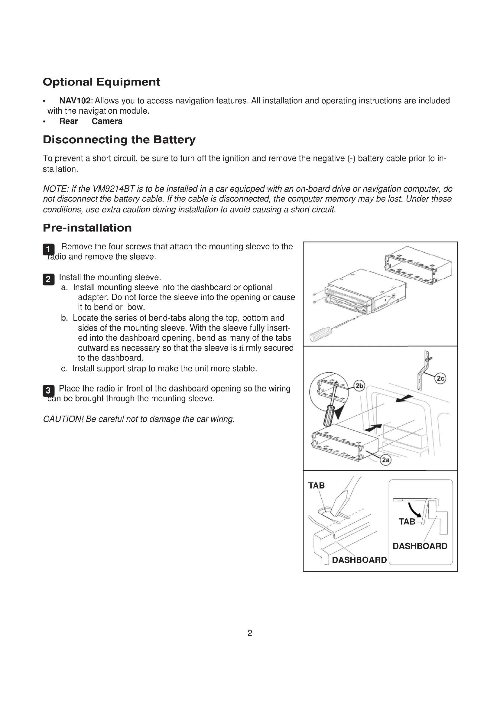
1 Remove the four screws that attach the mounting sleeve to the radio and remove the sleeve.
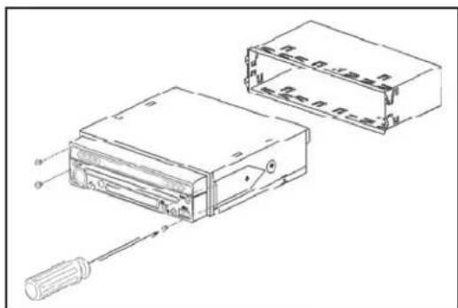
2 Install the mounting sleeve.
a. Install mounting sleeve into the dashboard or optional adapter. Do not force the sleeve into the opening or cause it to bend or bow.
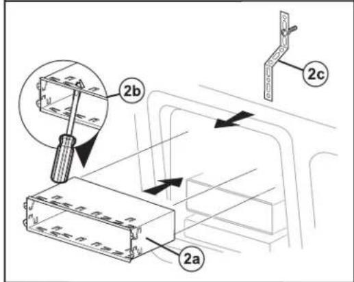
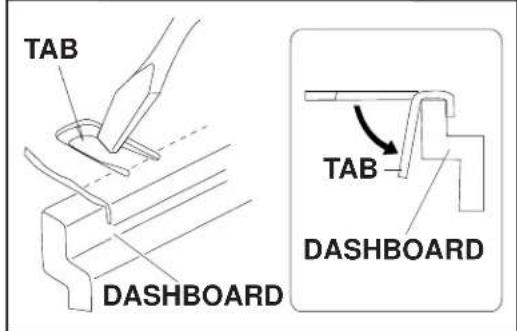
b. Locate the series of bend-tabs along the top, bottom and sides of the mounting sleeve. With the sleeve fully inserted into the dashboard opening, bend as many of the tabs outward as necessary so that the sleeve is firmly secured to the dashboard.
c. Install support strap to make the unit more stable.
3 Place the radio in front of the dashboard opening so the wiring can be brought through the mounting sleeve.
CAUTION! Be careful not to damage the car wiring.
Wiring
WARNING! Only connect the unit to a 12-volt power supply with proper grounding.
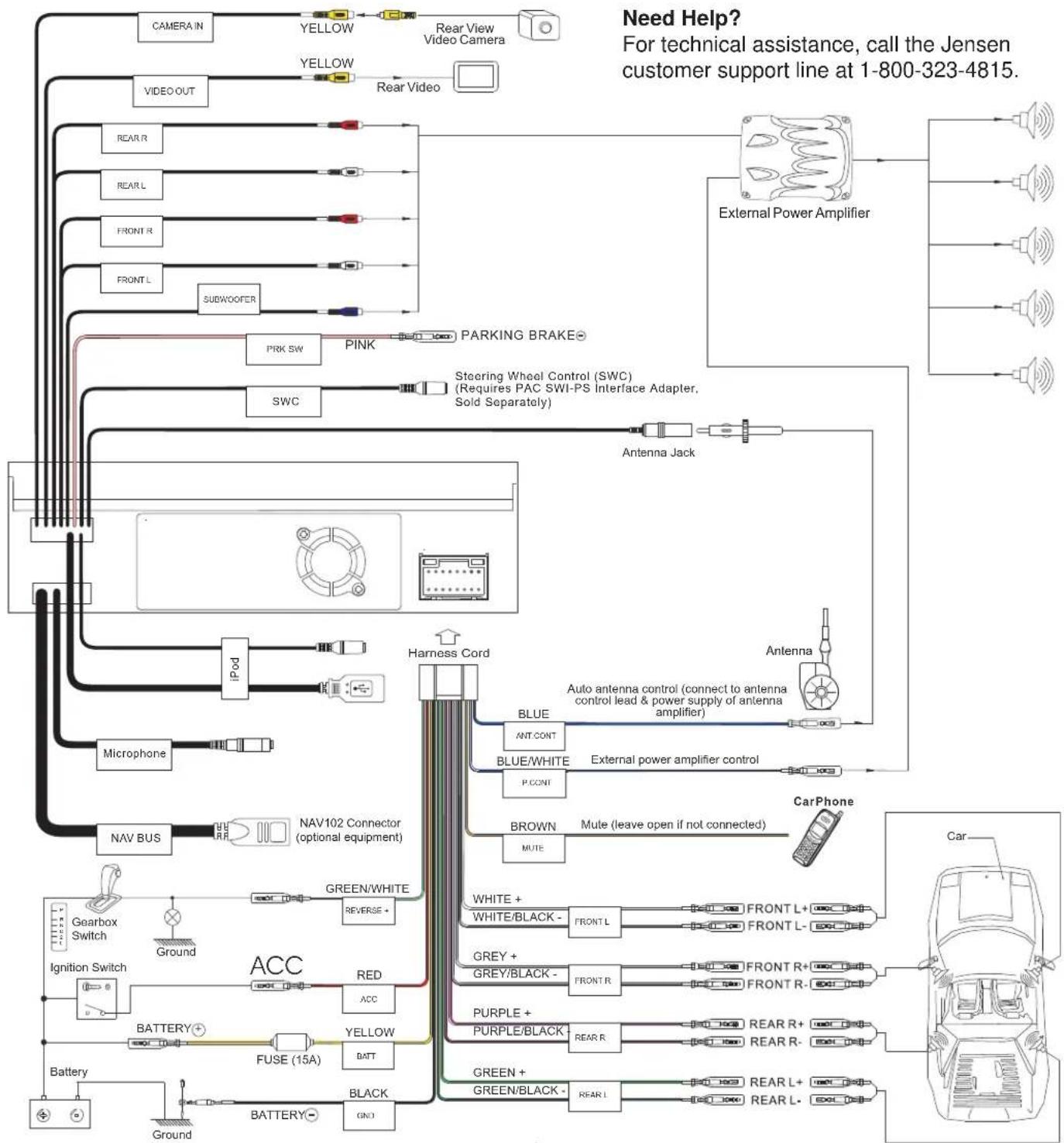
Complete wiring as illustrated in the wiring diagram on page 4. Once the wiring is complete, reconnect the battery negative terminal. If there is no ACC available, connect the ACC lead to the power supply with a switch.
NOTE: When replacing a fuse, be sure to use correct type and amperage to avoid damaging the radio. The VM9214BT uses one 15 amp fuse, located in the black filter box in-line with the main wire harness.
Final Installation
After completing the wiring connections, turn the unit on to confirm operation (ignition switch must be on). If unit does not operate, recheck all wiring until problem is corrected. Once proper operation is achieved, turn off the ignition switch and proceed with final mounting of the chassis.
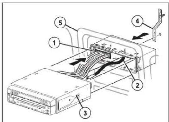
1 Connect wiring adapter to existing wiring harness.
2 Connect antenna lead.
3 Carefully slide the radio into the mounting sleeve, making sure it is right-side-up, and secure with the original 4 screws.
4 Attach one end of the perforated support strap (supplied) to the screw stud, which is screwed into the threaded insert on the back of the unit, using the hex nut provided. Fasten the other end of the perforated strap to a secure part of the dashboard either above or below the radio using the screw and hex nut provided. Bend the strap to position it as necessary.
5 Replace any items you removed from the dashboard.
ISO-DIN Installation
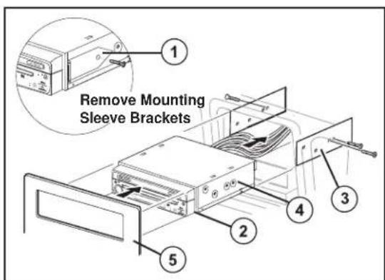
1 Remove mounting sleeve brackets.
2 Remove trim ring.
3 Mount factory brackets on new radio using existing screws from old radio.
4 Slide radio chassis into dash opening and secure.
5 Re-install dash panel.
CAUTION! The rear of the radio must be supported with the strap to prevent damage to the dashboard from the weight of the radio or improper operation due to vibration.
NOTE: For proper operation of the CD/DVD player, the chassis must be mounted within 20^ of horizontal. Make sure the unit is mounted within this limitation.
Wiring Diagram
IMPORTANT: Incorrect wiring connections can damage the unit. Follow the wiring instructions carefully, or have the installation handled by an experienced technician.
For basic iPod connectivity, you can use the white 30-pin to USB iPod cable that came with your Apple device. For iPod video or photo playback, you must purchase the jLink-USB cable. Connect the iPod cable to the rear chassis iPod inputs (USB / 3.5mm connectors) and route the iPod cable to an accessible part of the dash area for easy connectivity. For occasional iPod use, keep an iPod cable in your glove box and use it to connect the iPod to the front USB connector.
VM9214BT