Forza Goal - Football goal EXIT - Free user manual and instructions
Find the device manual for free Forza Goal EXIT in PDF.
Frequently Asked Questions - Forza Goal EXIT
User questions about Forza Goal EXIT
0 question about this device. Answer the ones you know or ask your own.
Ask a new question about this device
Download the instructions for your Football goal in PDF format for free! Find your manual Forza Goal - EXIT and take your electronic device back in hand. On this page are published all the documents necessary for the use of your device. Forza Goal by EXIT.
USER MANUAL Forza Goal EXIT
Warning! CHOKING HAZARD! - Small parts. Not for Children under 3 years old. Adult assembly required. This product should, at all times, be used by the child under direct supervision of an adult. OUTDOOR USE ONLY. Only for domestic use.

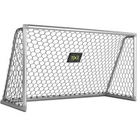
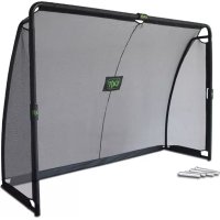
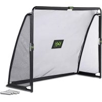
Congratulations on choosing the EXIT Forza soccer goal!
Have fun, be active and play outdoors......
That's what keeps driving us to develop innovative, quality toys for cool kids.
We do everything possible to develop safe products for children. As our products are classed as toys, we comply with the toughest consumer safety regulations. Before launching our products onto the market, we have independent tests carried out for certification. We also continuously test our production runs and periodically have independent tests performed again as a further check. Only products which live up to the highest EXIT Toys standard are marked with and recognized by the EXIT-brand.
"We want to thank you for your custom and your confidence in this product. We're sure your kids will have as much fun as we did during development. Being open-minded, we really appreciate all comments and ideas which will help us improve our products or develop new ones. You are invited to send your ideas to us at info@exittoys.com"
Please visit www EXITfoys.com and discover more cool new products.
The EXIT Toys team
2.0Warnings for safe use:
To simplify the assembly, please read the following instructions before beginning. It will be helpful to have an additional person assist in the assembly process.
Keep this manual for future reference.
Adult supervision is required at all times when Goal is used by children.
- To reduce risk of entanglement, keep small children away from net area at all times.
- When properly assembled and used as intended, this goal is designed to provide many hours of playing enjoyment.
- Never let children climb on goal as this can result in goal falling over causing serious injury or death.
- The metal frame of the soccer goal will conduct electricity. Lights, extension cords, and all such electrical equipment must never be allowed to come in contact with the soccer goal.
- Inspect the soccer goal before each use. Make sure the strips and all parts are correctly and securely positioned and attached. Tighten any loose hardware. Replace any worn, defective, or missing parts.
- Wear comfortable clothing free of hooks, snaps, drawstrings or anything which may snag or catch in the soccer goal mesh. Remove jewelry, necklaces, and earrings.
- Read all instructions and complete all assembly before using.
WARNING
ALWAYS ANCHOR GOAL
Unsecured Goal can fall over causing serious injury or death
3.0 Assembly and Installation Instructions
- Adequate overhead clearance is essential. Provide clearance for wires, tree limbs, and other possible hazards.
- Lateral clearance is essential. Place the Soccer Goal away from walls, structures, fences, and other play areas. Maintain a clear space on all sides of the soccer goal. A minimum of 3m from frame edge is recommended.
- The soccer goal is heavy, two able-bodied adults are required to set it up.
- Never set-up the soccer goal in heavy rain, wind or storm conditions, especially storms. It is recommended that the soccer goal be taken apart and stored.
- When moving the assembled soccer goal, have at least two people evenly the frame to lift the soccer goal off the ground.
- Place the soccer goal on a level surface before use.
- Secure the soccer goal against unauthorized and unsupervised use.
4.0 Care and Maintenance Instructions
Inspect the soccer goal before each use and replace any worn, defective, or missing parts.
The following conditions could present potential hazards:
- Missing, improperly positioned, or insecurely attached frame padding, barrier or enclosure
- Punctures, frays, tears, or holes worn in the soccer goal mesh.
- A bent or broken frame.
- Sharp protrusions on the frame or suspension.
- Loosened or missing hardware, system.
5.0 Guarantee Conditions & Service
The owner of this product has the following guarantees on the product:
- 5 years from date of purchase on the frame (regular use).
- A 6-month guarantee is given on the other parts (regular use).
- The guarantee only applies for material/construction errors of the product and/or parts thereof.
The guarantee is not applicable and/or is invalidated in the following cases:
- The soccer goal has been handled without due care, has been involved in an accident, or has been fitted with non-approved parts.
- Tire damage has occurred through extreme use such as skidding.
- The product has not been assembled as per instructions or has not been correctly maintained.
- Parts fitted afterwards do not match the product's technical specifications or original parts have not been used or have not been fitted correctly.
- The soccer goal is used for professional purposes (hire, schools, etc.).
- Technical repairs to the product were not carried out professionally.
- Replacement of parts such as tires were not carried out on time.
The owner of the product can only claim a guarantee by presenting the original bill for the purchase to Dutch Toys Group or the dealer from whom the product was bought.
If the claim under the guarantee is refused, then all costs incurred must be paid by the owner.
Guarantee is not transferable to third parties.
1.0 Einführung
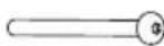
3 Upper Left L Tube 1pc
4 Upper Right R Tube 1pc
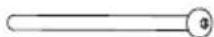
6 Back Top Bent Tube 2pcs
5 Front Side Tube 2pc

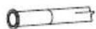
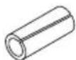
7 Back Side Tube 5pcs (Φ 50mm)
8 Back Left Bottom Tube 1pc
9 Back Right Bottom Tube 1pc


12 M8x20mm Bolt 4pcs
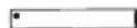
10 Anchor Tube 2pcs
11 Ground Spike 2pcs

14 M8 Arc Washer 8pcs
16 M8x55mm Bolt 2pcs

17 M8 Locknut 2pcs
18 M8x95mm Bolt 2pcs
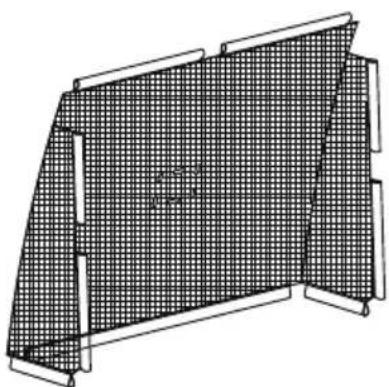
15 Net 1pc
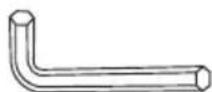
19 Allen Wrench 1pc

20 Wrench 1pc
21 Foam 3pcs

22 Big Logo 2pcs

24 Small Logo 2pcs
23 Small Logo 1pc

25 Spare cap 2pcs
Assembly steps / Montageschritte / Montage / Assemblée
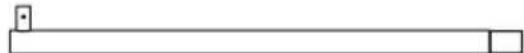
- EN: Attach two Top Cross Beams B (2) to the Top Cross Beam A (1) with two M8X20mm Bolts (12), two Spring Washers (13) and two Arc Washers (14) as shown.
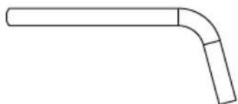
- EN: Find the Upper Right L Tube (4) marked with 4. Attach the Upper Right L tube (4) to the Top Cross Beams B (2) with the M8X20mm Bolt (12), Spring Washer (13) and Arc Washer (14) as shown.
- EN: Slip the step 2 assemblies into the side sleeves on the Net (15) as shown.
- EN: Find the Upper Left L Tube (3) marked with 3 . Attach the Upper Left L Tube (3) to the Top Cross Beams B (2) with M8X20mm Bolt (12), Spring Washer (13) and Arc Washer (14) as shown.
- EN: Slip the Front Side Tube (5) into the side sleeves on the Net (15) as shown.
Insert the Front Side Posts (5) into the Upper Left L Tube (3) and Upper Right L Tube (4) until the button snap into place as shown.
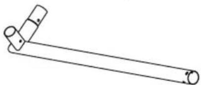
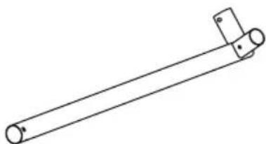
- EN: Find the Back Bottom Left Corner (8) and Back Bottom Right Corner (9) marked with 8 and 9 respectively. Slip the Back Bottom Left Corner (8) into the Net (15) sleeve and press the Back Bottom Left Corner (8) onto the Front Side Post (5) until the button snaps into place as shown. Repeat the above step to install the Back Bottom Right Corner (9). Then attach with two M8x55mm Bolts (16), M8 Arc Washers (14) and two M8 Locknuts (17) as shown, and tighten with Allen Wrength (19) and the Wrength (20).
- EN: Press the Back Side Tube(7) into two Back Side Tubes (7) until the push buttons snap into place as shown.
- EN: Slip the Step 7 assembly into the Net (15) bottom middle sleeve, and insert the assembly into the Back Bottom Left Corners (8) and the Back Bottom Right Corner(9) until the button snap into place as shown.
- EN: Insert the Back Top Bent Tube(6) into the Back Side Post(7) as shown. Make sure button snap into place.
- EN: Insert each Back Side Post (7) onto the Back Bottom Left Corner(8) and the Back Bottom Right Corner (9) until the button snap into place as shown. Connect each Back Top Bent Tube (6) to Top Left Bent Tube (3) and Top Right Bent Tube (4) using two M8x95mm bolts (18) and two M8 Ar washers (14) as shown. Use Allen Wrench (19) to tighten Bolts.
- EN: Install three Foams (21) as shown.
- EN: Wrap the three Foams (21) with the Small Logos (23 + 24) . Then apply Big Logo (22) on front and back side of Net (15).
- EN: Insert Anchor Tube(10) into Front Bottom Corner(5) as shown. Make sure the button snap into place
- EN: Firstly select a flat surface of ground or grass, make sure the assembly unit is away at least 3m from other structures or obstructions. Then drive the two Ground Spikes(13) which match two Anchor Tubes(12) with steel or rubber mallet. And then insert Anchor Tube(12) into Ground Spike(13) as shown.
NOTE: If you remove the net from the ground spikes, please use the Spare caps (25) to cover the Ground Spikes (11).