
Descale - Water Softener Atag - Free user manual and instructions
Find the device manual for free Descale Atag in PDF.

| Product type | Water softener |
| Brand | Atag |
| Model | Descale (5, 10, 15, 20, 30) |
| Article numbers | AA00010B, AA00020B, AA00030B, AA00040B, AA00050B |
| Resin tank dimensions | From 7" x 17" to 10" x 35" depending on model |
| Power supply | 230 V, 50 Hz, earthed socket not controlled by a switch |
| Required water pressure | 1.8 bar minimum, 8 bar maximum (with limiter if necessary) |
| Max water temperature | 35°C, frost-free |
| Main functions | Volumetric softening, automatic regeneration (delayed or immediate), built-in bypass, electronic controller with display, inlet and outlet hardness adjustment, flow detection, consumption history |
| Capacity (model 5) | 26 m³.°fH / 15 m³.°dH |
| Salt consumption per regeneration (model 5) | 0.55 kg |
| Regeneration cycles | Backwash, brine draw, rinse, refill, service – adjustable |
| Maintenance | Filling the salt tank, cleaning the injector, checking brine and drain lines, replacing the battery (CR2032 cell) |
| Safety | Check valve (class CA), bypass, frost protection, automatic shutdown in case of fault |
| Spare parts available | Injector, piston, motor, electronic board, seals, transformer, gears, battery |
| General information | Manual in French available, 64 pages, professional installer recommended |
Frequently Asked Questions - Descale Atag
User questions about Descale Atag
0 question about this device. Answer the ones you know or ask your own.
Ask a new question about this device
Download the instructions for your Water Softener in PDF format for free! Find your manual Descale - Atag and take your electronic device back in hand. On this page are published all the documents necessary for the use of your device. Descale by Atag.
USER MANUAL Descale Atag
natural_image
Black and white abstract image with horizontal lines and a blurred central figure (no text or symbols)ATAG
Descale
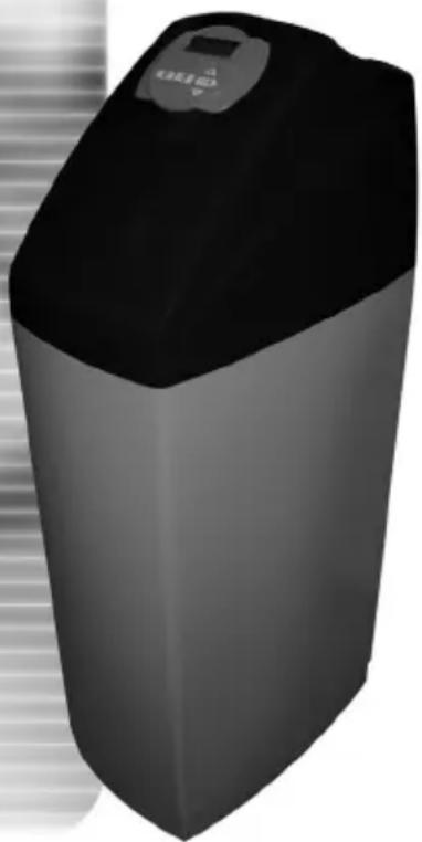
natural_image
3D rendering of a black cylindrical industrial water heater with a digital display (no text or symbols visible) | DECLARATION OF CONFORMITY | ||
| Manufacturer: | Clack Corporation, 4462 Dundorm Lane, Windsor, WI 53508, USA | ||
| Serial Number: | D-1303-D01 | ||
| Conforming Apparatus: | WS1, WS1CS, WS1TC, WS1CI | ||
| Apparatus Description: | Water Softening and Filtering Control Valves | ||
| EMC Competent Body: | Technology International (Europe) Limited60 Shrivenham Hundred Business Park,Shrivenham, Swindon, SN8 8TY, United KingdomTel: (44) 1793 783137 Fax (44) 1793 782310 | ||
| EMC TCF Document Reference No: | EMC-5133-TCF Issue 1 dated 2 February 2004 | ||
| EMC TCF and Safety Technical File Document Name: | WS1, WS1CS, WS1TC, and WS1CI Control Valve Series | ||
| EMC Technical Report and Certificate No: | R1303CLK1.DWS dated 12 February 2004, C1303CLK1.DWS dated 12 February 2004 | ||
| Harmonised EMC Standard(s) Referenced: | EN 50081-1:1997EN 50082-1:1997EN 55022:1998 Class BEN B1000-4-2:1995EN B1000-4-3:1997EN B1000-4-4:1995EN B1000-4-5:1995EN B1000-4-6:1996EN B1000-4-11:1994 | ||
| Safety Technical File Reference No.: | SF5133A1.CLA Issue 1 dated 29 January 2004 | ||
| Harmonised Safety Standard: | EN B1010:2001 | ||
| Responsible Person: | D.R.M. GreenEurolink (Europe) Ltd.Outalene House,Oak RoadWadchfield, Swindon, Wills. SN8 8TDUnited KingdomTel: (44) 1793 784545 Fax (44) 1793 784551 | ||
| We certify that the apparatus identified above conforms to the requirements of Council Directive BB/338/EEC, as amended by Directives 02/31/EEC and 93/88/EEC, on the approximation of the laws of the member state relating to electromagnetic compatibility, and Council Directive 73/23/EEC, as amended by Directive 83/88/EEC, on the approximation of the laws of the member state relating to electrical equipment designed for use within certain voltage limits. | |||
Signed:  Date: 12 February 2004D. R. M. Green Date: 12 February 2004D. R. M. Green | |||
natural_image
Exterior view of a modern office building (no signage)Manual for ATAG Descale
Page 4 - 22
natural_image
3D rendered image of a gray rectangular electronic device with a control panel and indicator lights (no text or symbols visible)Handleiding ATAG Descale
Pagina 44 - 63
Table of contents
1 Introduction 2
2 ATAG Descale Presentation 3
3 General installation advice 4
4 Installation instructions 5
5 Programming 7
6 Softener operation 15
7 Troubleshooting 16
1. Introduction
We would like to thank you for having acquired the ATAG Descale softener. We are convinced that this product will give you satisfaction as it has been manufactured with extreme care.
The ATAG Descale softener is delivered in a box and includes a by-pass valve. Please inspect carefully your device in presence of deliveryman to be sure it has not been damaged during transportation.
Before starting up your softener, please read this manual carefully. Handle your softener carefully.
This packaging can be recycled.
Please find a few hints that will allow you to use your softener in the best way.
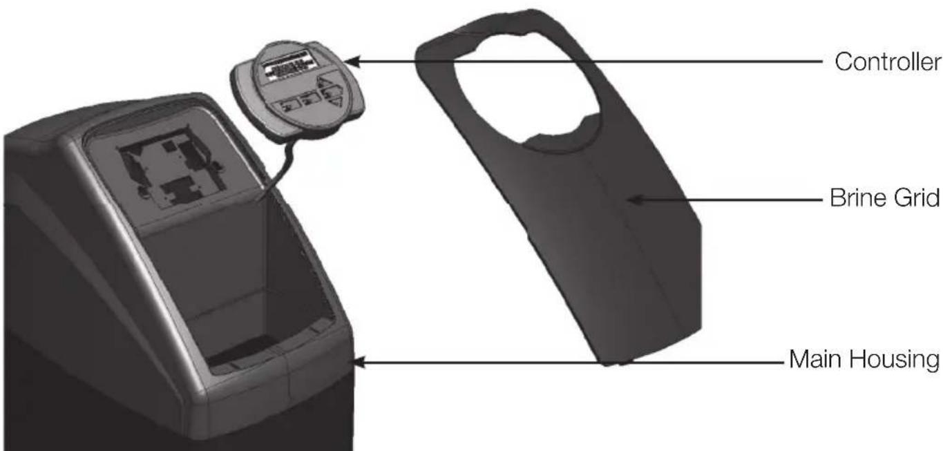
2. ATAG Descale Presentation
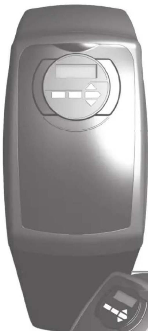
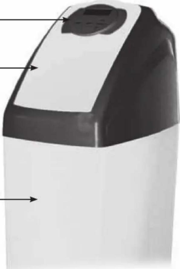
1. General overview
Controller
Brine Lid
Brine tank
natural_image
Exterior view of a modern kitchen appliance with control panel and buttons (no visible text or symbols)2. Main controller
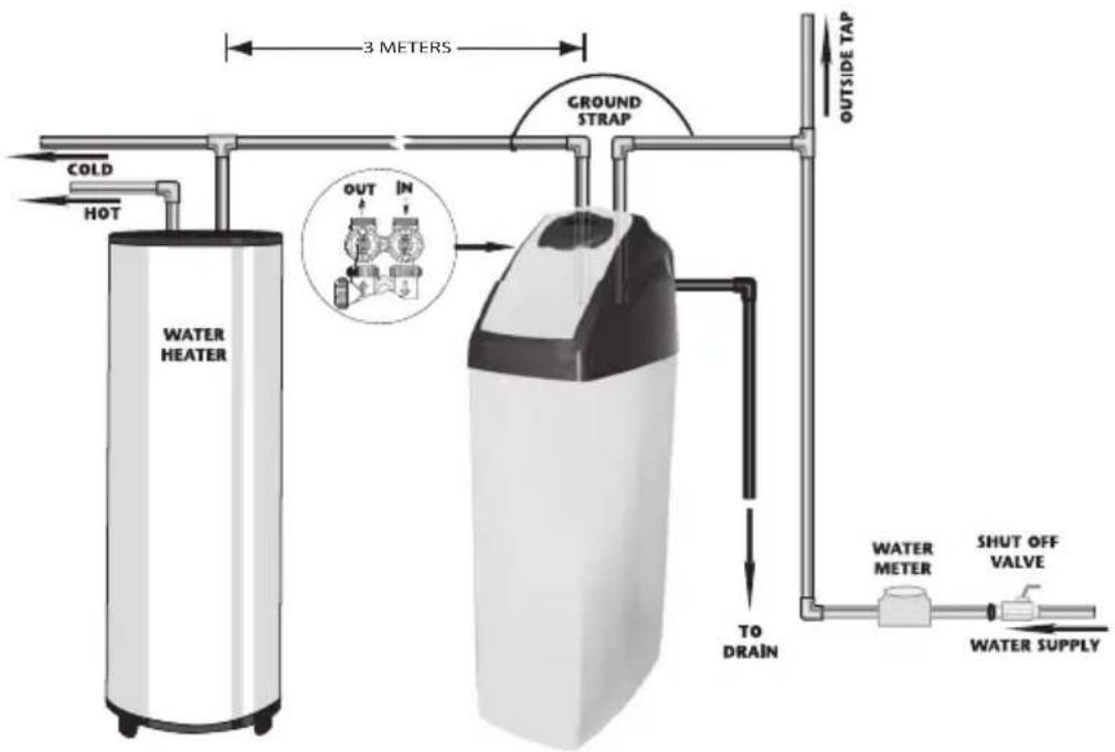
3. Residential installation
3. General advice on the installation
1. Pressure
A minimum pressure of 1.8 bars is needed to allow the valve to regenerate properly. Please do not operate over 8 bars. If this is the case, use a pressure reducer upstream of your installation.
2. Power connection
Be sure that power cannot be switched off accidentally at a wall switch. If the power cable is damaged, please ask a skilled electrician to change it.
3. Plumbing
The plumbing must be in good state. In Case of doubt, please change it. We advise the use of pre-filter upstream the installation.
4. Water Temperature
Feed water temperature must not exceed 35^ C and complete installation must not be allowed to freeze. (Irreversible damage).
Note : All electrical & plumbing should be done in accordance to all local codes.
4. Installation Instructions
REMARK The water softener must be connected according to the local regulations. The water softener must be equipped with a class CA security (check valve). The check valve must be placed in the cold water conduits before the water softener, and must be KIWA approved (by a third party). Also consult worksheet VEWIN 4.6.
When you choose your softener location, please take into account the following parameters :
1) Install your ATAG Descale softener in a chosen place on a flat firm and clean surface. Your ATAG Descale softener must be close to a drain line to allow an easy connection and check there is an electrical earth grounded plug to power the unit.
2) During cold weather, it is recommended to bring your ATAG Descale softener back to room temperature before operation. During hot weather, do not install your ATAG Descale softener in direct sunlight or in a room with a temperature above 45^ C
3) All plumbing for the water inlet, distribution and drain lines should be done correctly in accordance with the legislation in force at the time of the installation. The pipe size for the drain line should be a minimum of 20 mm ( ^3/_4 ).
4) All the soldering on the main plumbing and to the drain line should be done before connecting the ATAG Descale softener. Failing to do so can cause irreversible damage. For any maintenance, shut down water inlet, unplug your ATAG Descale softener and open the taps at the top and at the bottom of your house to drain your installation.
5) Manually add water in brine tank above the aircheck (around 10 liters). Do not fill with salt at the moment.
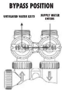
6) Place your ATAG Descale softener in the by-pass position. Turn on the main water supply. Open a cold soft water tap nearby and let run a few minutes or until your ATAG Descale softener is free from any foreign material (usually solder) that may have resulted from the installation. Once clean, close the water tap.
7) Switch on the power. Once plugged in the valve may do a cycle on its own in order to go to the service position. Display will alternate between installer name, time of day, flow rate and remaining capacity.
8) Push the REGEN button and hold it down for 3 seconds. The system will advance to the "first" position. When the motor stops, push the REGEN button repeatedly until "RINSE" shows in the left upper hand corner of display. Slowly turn the bypass to close the outlet and open the system inlet. Run water to the drain until it runs clear. Place your ATAG Descale softener in the by-pass position (System Inlet-Outlet closed – Full bypass). Push the REGEN button until unit is back in to softening mode.
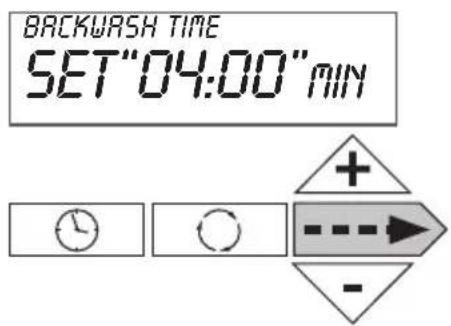
BACKWASH
"04:00" MIN
9) Once again, push the REGEN button and hold it down for 3 seconds. When the motor stops, push the REGEN button repeatedly until "BACKWASH" appears. Slowly open the inlet bypass valve 12 way to feed the softener with water. Allow water to slowly fill the tank. When a solid stream of water starts coming out of the drain line, open the by-pass inlet valve all the way and allow to run out the drain until water clears. Then slowly place the by-pass into "Normal position" mode (System inlet-outlet open) by opening the outlet side of bypass valve.
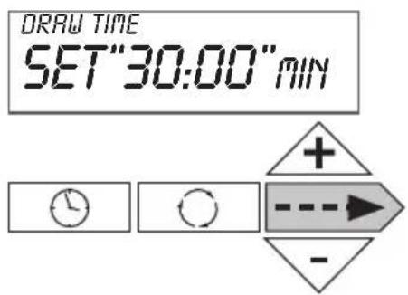
DRAY TIME
"30:00" MIN
10) Press the REGEN button until LCD display says “REGENERANT DRAW DN” or “REGENERANT DRAW UP”. Carefully check water level in the brine tank. If it decreases, got to the next step otherwise see section “TROUBLESHOOTING”
RINSE
"02:00" MIN
Figure 1
BYPASS POSITION
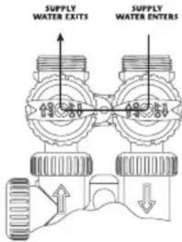
Figure 2
DIAGNOSTIC POSITION
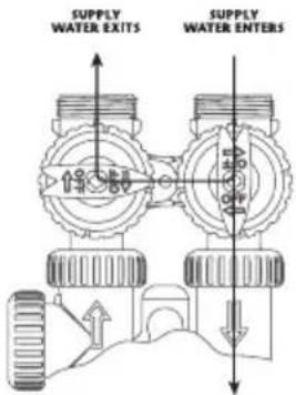
Figure 3
SHUT OFF POSITION
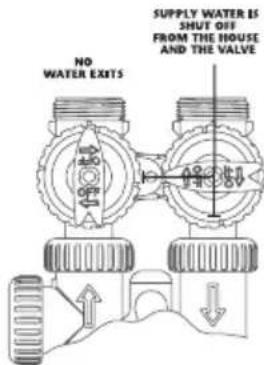
Figure 4
5. Programming
a) Display - Customer level
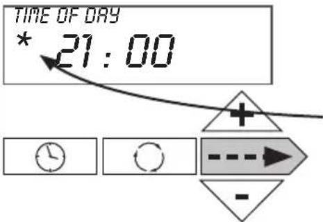
- Time of day
Time display – “REGEN TODAY” will alternate with current header if a regeneration is expected today.
Water meter detects water flow.
Push on → to go to the next parameter.
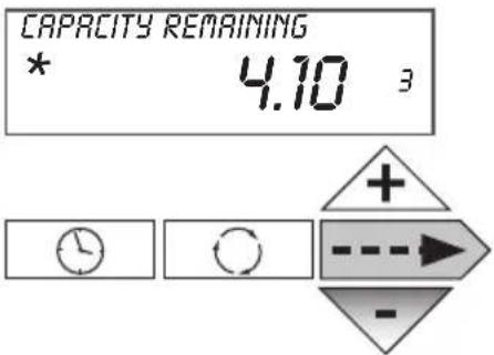
- Remaining capacity
Remaining Capacity Display – Each push on ▼ button decreases capacity by 0.01 M³.
Push on ---▶ to go to the next parameter.
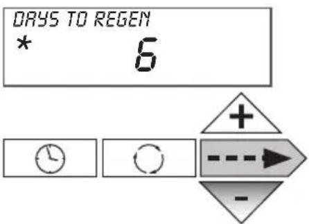
• Number of days until next regeneration
Displays the number of days until next regeneration occurs – Each push on ▼ button decreases days by 1.
Push on --> to go to the next parameter.
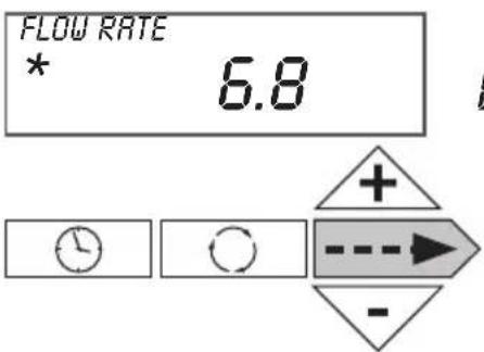
- Flow Flow rate display.
Push on --> to go to the next parameter.
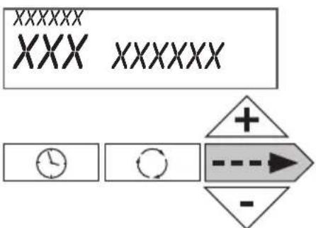
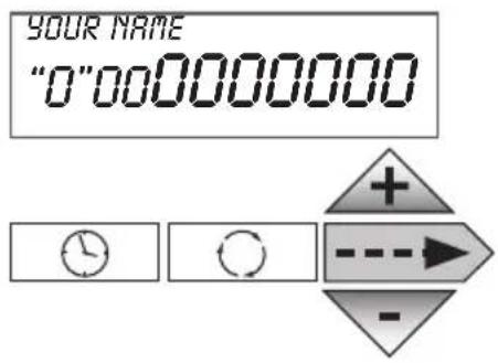
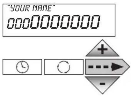
• Installer name and phone number
Displays installer name and phone number if they have been set.
Push on ----▶ to go to the next parameter.
b) Time of day setting – Customer level

Push on “ ” button
"Hours" setting. Number flashes.
By pushing on + or - , adjust the hours

Push on → to go to the next parameter
"Minutes" setting. Number flashes.
By pushing on + or - , adjust the minutes
Push on ⋯→ to go to the normal mode. Scrolling of the different parameters.
c) Hardness, calendar override, time of regeneration settings – Level experienced user & installer
Note: After 5 minutes without action, the controller switches back to the operating mode
Push and hold for 3 secondes -→ and +
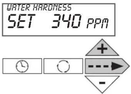
Set up raw water hardness in the unit selected in item e) (Normally ppm as default parameter)
Push on → to go to the next parameter
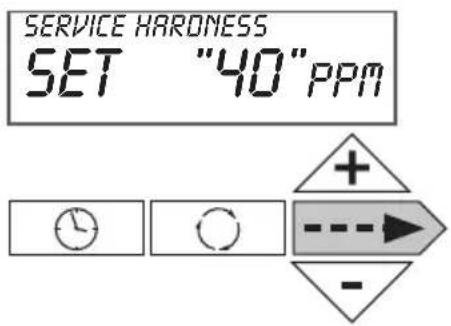
Set up residual hardness in softened water in the unit selected in item e) (Normally ppm as default parameter)
Push on → to go to the next parameter
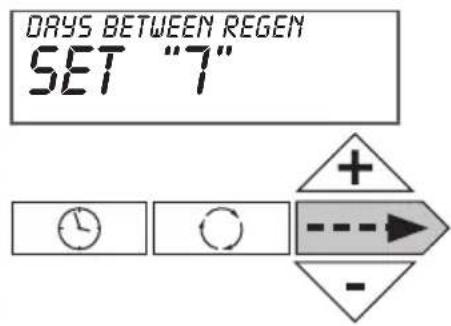
Set up number of days between two regenerations. Default setting is "14". Maximum number of days is "28" "Off" display indicates there is no forced regeneration.
Push on → to go to the next parameter
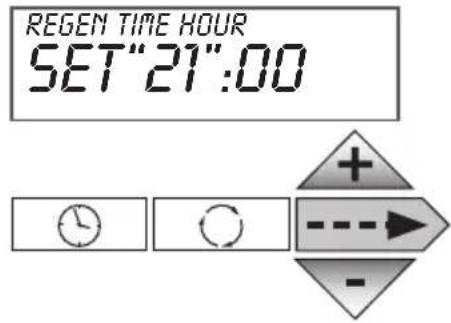
Set up time of regeneration (Hour). Number flashes. By pushing on + or - , adjust to the requested regeneration time
Push on ----> to go to the next parameter
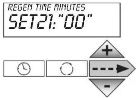
Set up time of regeneration (Minute). Number flashes. By pushing on + or - , adjust to the requested regeneration time
Push on --> to go to the normal mode. Scrolling the different parameters.
d) Operating mode, cycle time, capacity, reserve type settings, service alarm – installer and manufacturer setting
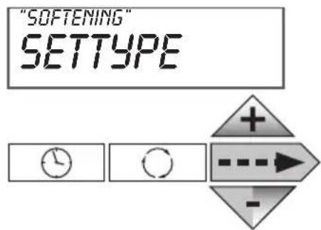
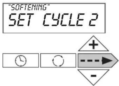
Push and hold for 3 seconds --- and - Choice of operating mode "SOFTENING" By pushing on + or - , we can switch to "FILTERING" mode In this brochure, we only describe "SOFTENING" mode.
Push on ---▶ to go to the next parameter
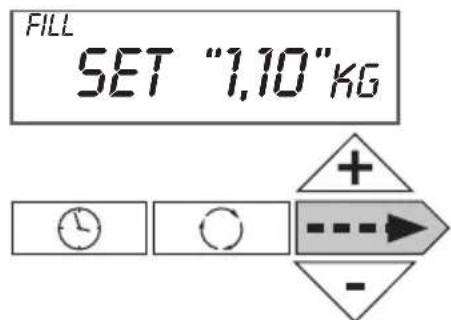
Set up the number of kg for cycle 1 (cycle definition in item e)
Push on ----> to go to the next parameter
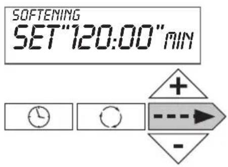
Set up the number of minutes for cycle 2
Push on ----▶ to go to the next parameter
Set up the number of minutes for cycle 3
Push on → to go to the next parameter
Set up the number of minutes for cycle 4
Push on ----▶ to go to the next parameter
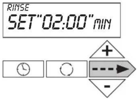
Set up the number of minutes for cycle 5
Push on → to go to the next parameter
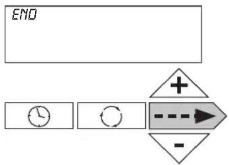
flowchart
graph TD
    A["END"] --> B["Clock Icon"]
    B --> C["Circle Icon"]
    C --> D["Directional Arrow + -"]
    D --> E["Arrow Right"]
    E --> F["-"]
Push on ----▶ to go to the next parameter
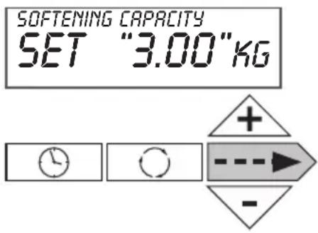
Set up softener capacity.
If hardness unit is ppm then capacity unit is kg If no unit is set for “hardness”, default unit is m^3
Push on → to go to the next parameter
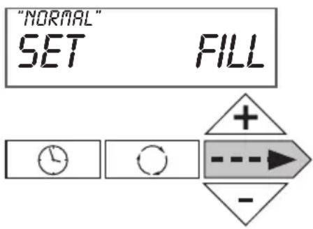
Set up brine tank refill (only be available if configured as a 25mm Pre-Fill Up-Flow brining softener)
You can select between "NORMAL" and "PROPORTIONAL".
Proportional brining will only be available if configured as a 25mm Pre-Fill Up-Flow brining softener.
Proportional brining corresponds with ratio of used capacity on total capacity multiplied by refill for a complete regeneration of resin bed.
Push on ---▶ to go to the next parameter
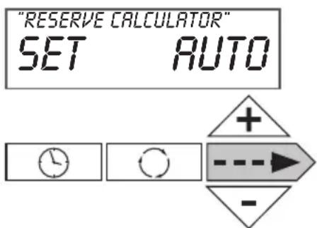
Set up reserve type
In “AUTO” position, capacity and reserve are automatically calculated.
Note : “OFF” position corresponds with a timeclock use with a regeneration frequency.
“M3”, “NA”, “NORES” position does not work with “SOFTENING” mode.
Other option for special applications
Push on ---▶ to go to the next parameter
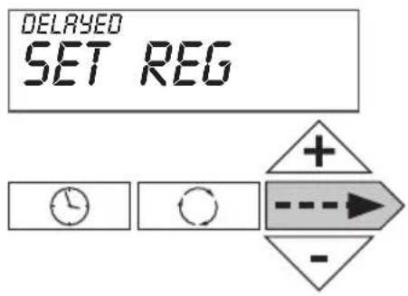
Set up Start of Regeneration:
– Delayed: regeneration on a specific time
- Immediate: immediate regeneration when volume is at 0
- Delay+immediate: delayed regeneration with override on 0 volume
Push on --> to go to the next parameter
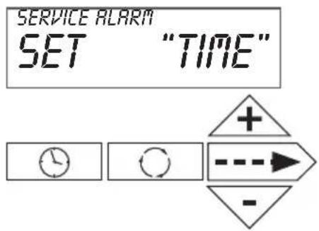
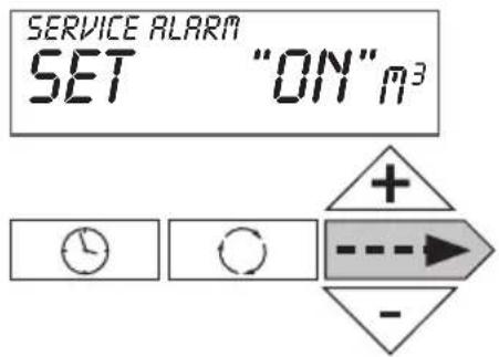
Set up service alarm based on (TIME), on volume ( m^3 ), on both (BOTH). No service alarm (OFF)
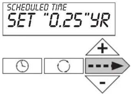
If setting based on time
Set up service alarm based on (TIME) – setting every 3 months.
Push on --> to go to the next parameter
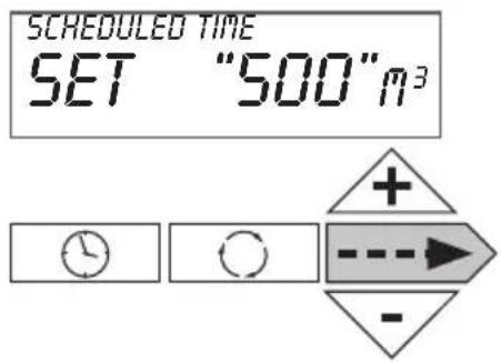
If setting based on volume or both
Set up service alarm based on volume ( m^3 )
Setting every 500 m ^4
Push on → to go to the normal mode
e) Valve type, units, cycle definition and installer data settings - Level Manufacturer & installer
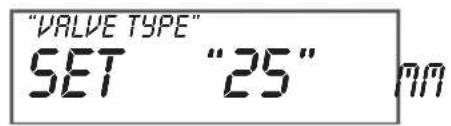
Push and hold for 3 seconds on --▶ and ▼ and again push and hold for 3 seconds on --▶ and ▼. Set up valve body.
Please select "25 mm" or simply validate because it is defined as default parameter.
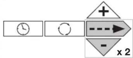
flowchart
graph LR
    A["Clock"] --> B["Reset"]
    B --> C["Arrow to Right"]
    C --> D["Arrow to Down"]
    D --> E["x 2"]
Push on → to go to the next parameter
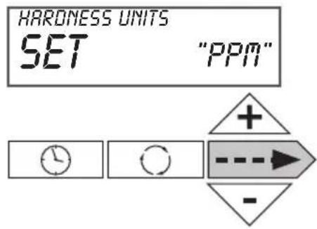
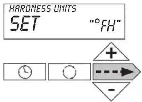
Set up hardness unit.
You can choose between ppm, °dH (German degree), °fH (French degree), NA (no hardness setting). Default value is ppm.
We recommend "ppm"
Push on → to go to the next parameter
Regeneration Cycles Softening
| WS1CI & WS1.25CIDownflow RegenerantRefill After Rinse | WS1CI & WS1.25CIDownflow RegenerantPrefill | WS1CI OnlyUpflow RegenerantRefill After Rinse | WS1CI OnlyUpflow RegenerantPrefill |
| 1^st Cycle: Backwash 2^nd Cycle: dn Brine 3^rd Cycle: Backwash 4^th Cycle: Rinse 5^th Cycle: Fill 6^th Cycle: End | 1^st Cycle: Fill 2^nd Cycle: Softening 3^rd Cycle: Backwash 4^th Cycle: dn Brine 5^th Cycle: Backwash 6^th Cycle: Rinse 7^th Cycle: End | 1^st Cycle: UP Brine 2^nd Cycle: Backwash 3^rd Cycle: Rinse 4^th Cycle: Fill 5^th Cycle: End | 1^st Cycle: Fill 2^nd Cycle: Softening 3^rd Cycle: UP Brine 4^th Cycle: Backwash 5^th Cycle: Rinse 6^th Cycle: End |
It is not recommended to change control valves from downflow to upflow brining or vice versa in the field. The valve bodies for downflow and upflow are unique to the regeneration type and should not be interchanged. A mismatch of valve body and regeneration piston will result in hard water bypass during service.
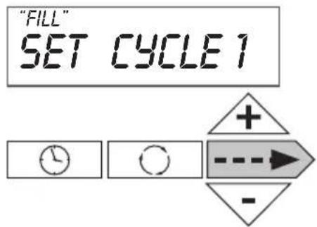
Choice of cycle 1 (in our example, backwash)
You can choose between backwash, fill, regenerant drawn dn, regenerant draw up, fast rinse, softening, end
Push on --> to go to the next parameter
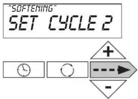
Choice of cycle 2 (in our example Regenerant draw down)
You can choose between backwash, regenerant draw down, regenerant drawn up, fast rinse, softening, end
Push on ---▶ to go to the next parameter
Push on → to go to the next parameter
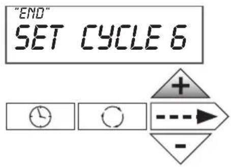
Choice of last cycle (in our example 6 but possibility up to 9 cycles).
Push on ---▶ to return to normal mode
Push and hold on “☐” and + to set up phone number
Set up phone number in scrolling number with “+” and “-” arrows. Go to the next number by pushing on - until you obtain the correct phone number.
Push on ▶ to go to the next parameter
Set up the name of softener or installer in scrolling letters with “+” and “-”. Go to the next letter by pushing on --▶ until you obtain the correct name.
Push on → to go to the normal mode
f) Historical data – installer level
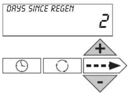
Push and hold for 3 seconds on + and -. Number of days since last regeneration
Push on ----▶ to go to the next parameter
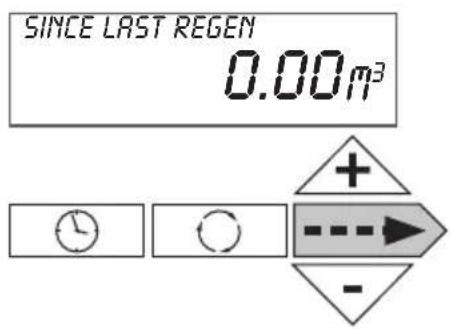
Consumption since last regeneration
Push on → to go to the next parameter
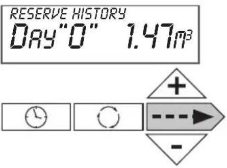
Reserve history (at the time of regeneration)
Day 0 = Today
Day 1 = Yesterday
Day 2 = The day before yesterday
Day 6 (max)
Not visible if time clock use or volume mode
Push on ----▶ to go to the next parameter
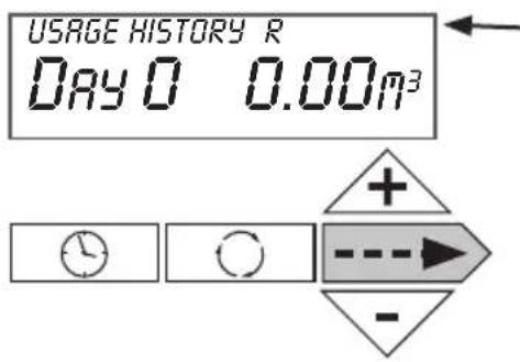
R is displayed if regeneration has occurred in the last 24 hours
Usage history
Day 1 = Yesterday
Day 2 = The day before yesterday
Day 63 (max) = 63 days before
Push on → to go to the next parameter
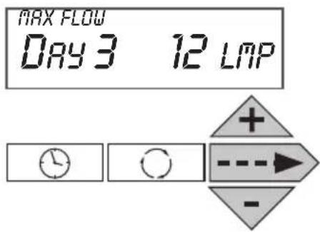
Maximum flow rate in the last 7 days
Possible reset by pushing and holding + and - for 5 seconds
Push on ----> to go to the next parameter
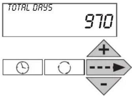
Push and hold twice on + and - during 3 seconds
Total number of days since start up
Only when controller is switched on.
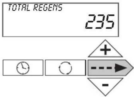
Push on → to go to the next parameter
Total number of regeneration since start up
Push on --> to go to the next parameter
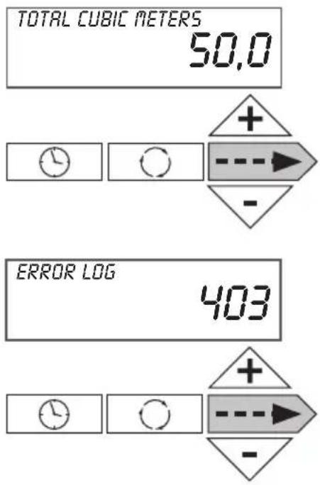
Number of used M^3 since start up
Push on --> to go to the next parameter
Records of last 10 potential errors generated by the controller.
Push on → to go to the normal mode
6. Softener operation
Meter Regeneration
In normal use, the LCD display alternates between time of day, remaining capacity (m3), flow rate, number of days until next regeneration and the installer or softener name. At the time of regeneration, controller compares remaining capacity with reserve and decides wether to start or not start a regeneration. Softener can have as an option of a blending device to insure a residual hardness in softened water.
Controller during regeneration
During regeneration, the LCD display shows the cycle number, its name and the remaining time for this cycle. When all the cycles are done, the valve comes back in to service position. The controller can handle co-current regeneration (brining in the same way as flow), counter current (upflow brining), with wet (fill after rinse) or dry brine tank (prefill) and normal or proportional brining.
Valve operation during programming
To enter program mode the valve has to be in service. While in the program mode, the valve will continue to operate normally monitoring all information. The programming is stored in permanent memory.
Valve operation during a power failure
During a power failure all control displays and programming will be stored for use when power is resumed. The control will retain these values for years, if necessary without loss. The control will be inoperative and any calls for regeneration will be delayed. The control will, upon power resumption operate normally from the point where it was interrupted.
7. Troubleshooting
| PROBLEM ERROR followed by code number | CAUSE ACTION | |
| Error Code 101Unable to recognize start of regeneration | a. Not reading piston positionb. Incorrect Assembly | a. Resynchronize software with piston position. Press NEXT and REGEN for 3 secondsb. Disassemble drive bracket, verify wires are in guides & reassemble. |
| Error Code 102Unexpected stall | a. Mechanical binding a. Check Piston and spacer stack assembly for foreign matter | |
| Error Code 103Motor ran too long, timed out trying to reach home position. | a. High drive forces on piston a. Loosen | drive cap gear 1⁄4 turn or replace. Address high drive forces. |
| Error Code 104Motor ran too long, timed out trying to reach home position.IF OTHER ERROR CODES DISPLAY CONTACT THE FACTORY | a. Control valve piston not in home positionb. Motor not inserted fully to engage pinion, motor wires broken or disconnected, motor failurec. Drive gear label dirty or damaged, missing or broken geard. Drive bracket incorrectly aligned to back platee. PC Board is damaged or defectivef. PC board incorrectly aligned to drive bracket | a. Press NEXT and REGEN for 3 secondsb. Check motor and wiring.Replace motor if necessaryc. Replace or clean drive gard. Reseat drive brackete. Remplace PC boardf. Ensure PC board is correctly snapped on to drive bracket |
| PROBLEM ERROR CAUSE ACTION | ||
| Control valve stalled in regeneration | a. Motor not operatingb. No electric power at outletc. Defective transformerd. Defective PC boarde. Broken drive gear or drive cap assemblyf. Broken piston retainerg. Broken main or regenerant piston | a. Replace motorb. Repair outlet or use working outletc. Replace transformerd. Replace PC Boarde. Replace drive gear or drive cap assemblyf. Replace drive cap assemblyg. Replace main or regenerant piston |
| Control valve does not regenerate automatically when REGEN button is depressed and held | a. Transformer unpluggedb. No electric power at outletc. Broken drive gear or drive cap assemblyd. Defective PC Board | a. Connect transformerb. Repair outlet or use working outletc. Replace drive gear or drive cap assemblyd. Replace PC Board |
| PROBLEM ERROR CAUSE ACTION | ||
| Water softener delivers hard water | a. Bypass valve in Bypass positionb. Meter connection disconnectedc. Restricted/stalled meter turbined. Defective metere. Defective PC boardf. Set-up error | a. Put bypass valve in position serviceb. Connect meter to PC Boardc. Remove meter and check for rota-tion or foreign matterd. Replace metere. Replace PC Boardf. Check control valve set up procedure |
| Time of day flashes on and off | a. Battery back up maintains time of day up to 2 years in event of power outage and battery is depleted.Time of day flashes when battery is depleted | a. Reset time of day and replace battery on PC Board (Lithium coin type Battery 2032) |
| Softener delivers hard water a. | Bypass valve is open or defectiveb. No salt or low salt level in brine tankc. Softener fails to draw brined. Excessive water usagee. Insufficient brine level in brine tankf. Meter faultyg. Raw water hardness fluctuation | a. Close bypass valve or replaceb. Add salt to brine tank and maintain salt level above water level c. See problem “Softener fails to draw brine”d. Check capacity settingse. Check brine refill setting and refill flow restrictor for blockagef. Test meter and clean or replace meterg. Test raw water hardness and adjust settings to highest known hardness |
| Unit uses too much salt a. Improper brine refill settingb. Improper settingsc. Excessive water usaged. Leaking faucets, toilets, ... | a. Check brine refill setting for proper salt dosageb. Check water hardness and reevalu- luate capacity setting specificationc. See problem “Excessive water in brine tank”d. Repair or replace those items | |
| Softener delivers salt water a. Low water pressureb. Excessive water in brine tankc. Wrong size injector | a. Check incoming water pressure – Mini 1.8 barsb. See problem “Excessive water in brine tank”c. Install correct injector | |
| Excessive water in brine tank a. Injector is pluggedb. Faulty piston/seal assemblyc. Plugged or kinked drain lined. Backwash flow controller closed offe. Defective brine line flow control | a. Remove injector and clean portsb. Replace piston/seal assemblyc. Correct any kinking or plugging of drain lined. Check backwash flow controllere. Remplace brine line flow controller | |
| Type | Descale 5 | Descale 10 | Descale 15 | Descale 20 | Descale 30 |
| Art.number | AA00010B | AA00020B | AA00030B | AA00040B | AA00050B |
| resin volume (litres) | 5 | 10 | 15 | 20 | 30 |
| dimensions resin tank (diam xh) | 7" x 17" | 8" x 17" | 7" x 35" | 8" x 35" | 10" x 35" |
| injector | V3010-1A | V3010-1A | V3010-1B | V3010-1C | V3010-1C |
| colour | black | black | brown | violet | red |
| type DLFC 12m/h | V3162-013 | V3162-017 | V3162-013 | V3162-017 | V3162-017 |
| capacity m3. °Fh - m3°dH | 26 - 15 | 52 - 30 | 78 - 44 | 105 - 59 | 156-87 |
| salt usage kg | 0,55 | 1,10 | 1,65 | 2,20 | 3,30 |
| Regeneration | |||||
| Filling of salt tank - Fill - kg | 0,55 | 1,10 | 1,10 | 2,20 | 3,30 |
| Company - Softening - min | 120 | 120 | 120 | 120 | 120 |
| Regeneration up - Reg Draw Up - min. | 25 | 30 | 30 | 30 | 30 |
| Backwash rinse - backwash - min | 3 | 4 | 5 | 5 | 6 |
| Rinse - rinse - min | 2 | 2 | 3 | 3 | 4 |
| End - End | |||||
| Settings | adjust with + and - | see page | |||
| push at the same time → and + | WATER HARD | measure & set | 10 | ||
| push → | SERVICE HARD | measure & set | 10 | ||
| push → | DAYS BETWEEN | / | 10 | ||
| push → | REG TIME HOUR | x:00 set | 11 | ||
| push → | REG TIME MIN | 0:xx set | 11 | ||
| push → | ...... | set | |||
| push ⏻ | TIME HOUR | set | 9 | ||
| push ⏻ | TIME HOUR | set | 9 | ||
| push ⏻ | ...... | set | |||
| push q | 1x | REG TODAY | regeneration at 0h00 | ||
| push q | ±4 sec | REGENERATIE | immediate regeneration | ||
Table des matières
flowchart
graph TD
    A["END"] --> B["Clock Icon"]
    B --> C["Circle Icon"]
    C --> D["Directional Arrow: +, -"]
    D --> E["Arrow to Right"]
Si réglage au temps
natural_image
Exterior view of a modern kitchen appliance with black and white casing (no visible text or symbols)2. Hoofdsturing

NORMALE BEDRIJFSPOSITIE
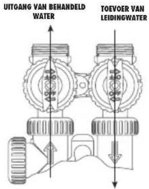
Figuur 1
BYPASS POSITIE
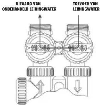
Figuur 2
DIAGNOSTIEKPOSITIE
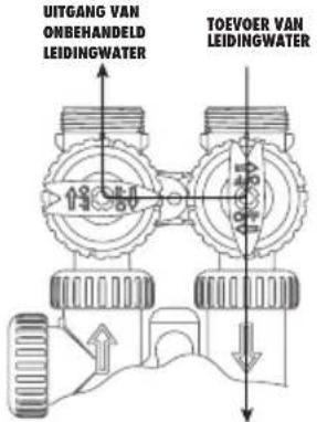
Figuur 3
AFGESLOTEN POSITIE
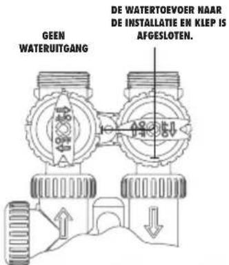
Figuur 4
5. Programming
Druk op .
Stel de minuten in ("Minutes"). De regelbare waarde begint te flikkeren.
flowchart
graph LR
    A["Clock"] --> B["Refresh"]
    B --> C["Directional Arrow + - -"]
    C --> D["Dashed Arrow"]
flowchart
graph LR
    A["Clock"] --> B["Refresh"]
    B --> C["Directional Arrow + - -"]
    C --> D["D"]
flowchart
graph LR
    A["Clock"] --> B["Refresh"]
    B --> C["Directional Arrow: +, -"]
    C --> D["D"]

- ATAG
- Descale
- Table of contents
- Introduction
- ATAG Descale Presentation
- General overview
- Main controller
- Residential installation
- General advice on the installation
- Pressure
- Power connection
- Plumbing
- Water Temperature
- Installation Instructions
- Programming
- a) Display - Customer level
- - Time of day
- - Remaining capacity
- • Number of days until next regeneration
- • Installer name and phone number
- b) Time of day setting – Customer level
- c) Hardness, calendar override, time of regeneration settings – Level experienced user & installer
- d) Operating mode, cycle time, capacity, reserve type settings, service alarm – installer and manufacturer setting
- Set up softener capacity.
- Set up reserve type
- Set up Start of Regeneration:
- If setting based on time
- If setting based on volume or both
- e) Valve type, units, cycle definition and installer data settings - Level Manufacturer & installer
- f) Historical data – installer level
- Usage history
- Maximum flow rate in the last 7 days
- Number of used M3 since start up
- Softener operation
- Meter Regeneration
- Controller during regeneration
- Valve operation during programming
- Valve operation during a power failure
- Troubleshooting
- Table des matières
- Si réglage au temps
- Hoofdsturing
Brand : Atag
Model : Descale
Category : Water Softener