RELAYIOMINI - Programmable electronic board Tripp Lite - Free user manual and instructions
Find the device manual for free RELAYIOMINI Tripp Lite in PDF.

| Product Type | Programmable I/O Relay Card |
| Brand | Tripp Lite |
| Model | RELAYIOMINI |
| Dimensions | 68 x 43 mm |
| Weight | 35 g |
| Power Supply | 8 ~ 20 V DC |
| Power Consumption | 0.8 Watts |
| Number of Output Relays | 3 (R1, R2, R3) |
| Output Current Rating (per relay) | 24 V DC / 1 A max |
| Remote Shutdown Input | Yes (input terminal, 12 V DC) |
| Operating Temperature | 0 ~ 40 °C |
| Operating Humidity | 10 ~ 80 % |
| Installation | Replaces the USB card in a mini-slot of SmartOnline™ UPS systems (5-10 kVA) |
| Main Functions | UPS status monitoring, remote shutdown, alarm signaling (global, power failure, low battery) |
| Package Contents | RELAYIOMINI card, owner's manual |
| Warranty | 2 years (1 year outside U.S. and Canada) |
| Maintenance and Cleaning | No special maintenance required. Avoid excessive moisture and dust. |
| Safety | Do not use in life support applications or in the presence of flammable anesthetics. |
| Spare Parts and Repairability | Not user-serviceable. Contact Tripp Lite support for returns. |
| General Information | Specifications subject to change without notice. Unique serial number on product label. |
Frequently Asked Questions - RELAYIOMINI Tripp Lite
User questions about RELAYIOMINI Tripp Lite
0 question about this device. Answer the ones you know or ask your own.
Ask a new question about this device
Download the instructions for your Programmable electronic board in PDF format for free! Find your manual RELAYIOMINI - Tripp Lite and take your electronic device back in hand. On this page are published all the documents necessary for the use of your device. RELAYIOMINI by Tripp Lite.
USER MANUAL RELAYIOMINI Tripp Lite
1.1 Product Features 2
1.2 Package Contents 2
2. Installation 2
2.1 System Requirements 2
2.2 Installing 2
3. Specifications 3
- Warranty & Warranty Registration 3
Use of this equipment in life support applications where failure of this equipment can reasonably be expected to cause the failure of the life support equipment or to significantly affect its safety or effectiveness is not recommended. Do not use this equipment in the presence of a flammable anesthetic mixture with air, oxygen or nitrous oxide.

1111 W. 35th Street, Chicago, IL 60609 USA www.triplite.com/support
1. Introduction
1.1 Product Features
The RELAYIOMINI is a programmable UPS management device featuring:
3 relay output contacts
Input signal to shutdown UPS
The RELAYIOMINI allows you to:
Monitor UPS status and events
Perform remote system shutdowns
1.2 Package Contents
This Package Contains:
RELAYIOMINI
Owner's Manual
2. Installation and Setup
2.1 System Requirements
The RELAYIOCARD supports various Tripp Lite SmartOnLine™ UPS Systems (5-10kVA) equipped with the mini slot.
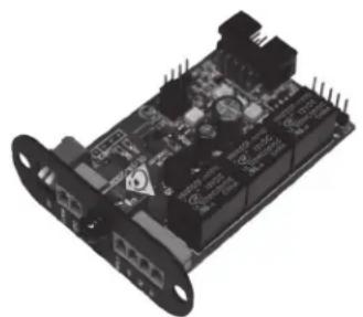
2.2 Installing
The RELAYIOMINI card will replace your UPS system's USB card to add dry contact support. To install the new card, simply unscrew the two screws holding your current USB card in place and pull out the card. Disconnect the ribbon cable from the USB card. Then, attach the ribbon cable to the new RELAYIOMINI card, slide the card into the same slot and re-attach the two screws you removed earlier.
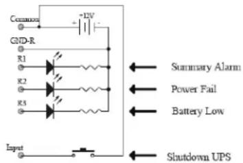
Application Example
Using the default settings, set SW1 and SW2 to ON. Connect 12V DC supply between the common and ground terminals. Connect equipment to R1~R3 terminals. Install a push button from the common terminal to the input terminal. To remotely shut down the UPS, close this circuit for a minimum of 3 seconds.
3. Specifications
| Technical Specifications | |
| Size 68 x 43 mm | |
| Weight 35 g | |
| Operating Temperature 0 ~ 40°C | |
| Operating Humidity 10 ~ 80% | |
| Power Input 8~20V DC | |
| Power Consumption 0.8 Watts | |
| Output Contact Rating | ||
| Maximum | ||
| DC Voltage DC Current | ||
| Relay R1~R3 24V | A | |
| Input Rating | ||
| Maximum | ||
| DC Voltage DC Current | ||
| Input 24V 10mA | A | |
Internal Circuit
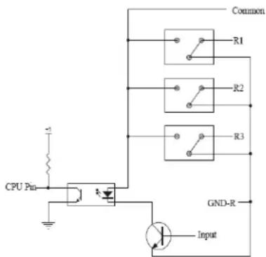
| I/O Pinout | ||
| GND-R: Ground for relays | ||
| Common: 12~24V DC | ||
| Default Alarm Event | ||
| R1 Summary Alarm | ||
| R2 Power Fail | ||
| R3 Battery Low | ||
| Input: Remote shutdown | ||
| All On Status | ||
| SW1 | ON | Communicating |
| SW2 | ON | Communicating |
4. Warranty & Warranty Registration
LIMITED WARRANTY
Sell wth t r i t t t t t t t t t t t t t t t t t t t t t t t t t t t t t t t t t t t t t t t t t t t t t t t t t t 0
THIS WARRANTY DOES NOT APPLY TO NORMAL WEAR OR TO DAMAGE RESULTING FROM ACCIDENT, MISUSE, ABUSE OR NEGLECT. SELLER MAKES NO EXPRESS WARRANTYES OTHER THAN THE WARRANTY EXPRESSLY SET FORTH HEREIN. EXCEPT TO THE EXTENT PROHIBITED BY APPLICABLE LAW. ALL IMPLIED WARRANTYES, INCLUDING ALL WARRANTY OF MERCHANTABILITY OR FITNESS, ARE LIMITED IN DURATION TO THE WARRANTY PERIOD SET FORTH ABOVE; AND THIS WARRANTY EXPRESSLY EXCLUDING ALL INCIDENTAL AND CONSEQUENTIAL DAMAGES. (Some states do not allow limitations on how long an implied warranty lasts, and some states do not allow the exclusion or limitation of incidental or consequential damages, so the above limitations or exclusions may not apply to you. This Warranty gives you specific legal rights, and you may have other rights which vary from jurisdiction to jurisdiction.)
WARNING: The individual user should take care to determine prior to use whether this device is suitable, adequate or safe for the use intended. Since individual applications are subject to great variation, the manufacturer makes not representation or warranty as to the suitability or fitness of these devices for any specific application.
Not compatible with PoE (Power over Ethernet) applications.
WARRANTY REGISTRATION
Visit www.triplite.com/warranty today to register the warranty for your new Tripp Lite product. You'll be automatically entered into a drawing for a chance to win a FREE Tripp Lite product!
No purchase necessary. Void where prohibited. Some restrictions apply. See website for details.
Regulatory Compliance Identification Numbers
For the purpose of regulatory compliance certifications and identification, your Tripp Lite product has been assigned a unique series number. The series number can be found on the product nameplate label, along with all required approval markings and information. When requesting compliance information for this product, always refer to the series number. The series number should not be confused with the marking name or model number of the product.
Tripp Lite has a policy of continuous improvement. Product specifications are subject to change without notice.
1111 W. 35th Street, Chicago, IL 60609 USA
www.triplite.com/support
1111 W. 35th Street, Chicago, IL 60609 USA
www.triplite.com/support
1111 W. 35th Street, Chicago, IL 60609 USA
www.triplite.com/support
Specifications techniques