
PowerLine Webcast 2 - Powerline Adapter TECHNISAT - Free user manual and instructions
Find the device manual for free PowerLine Webcast 2 TECHNISAT in PDF.

| Product type | Powerline adapter |
| Brand | TechniSat |
| Model | PowerLine Webcast 2 |
| Dimensions (L x W x H) | 49 x 56 x 112 mm |
| Weight | Approx. 150 g (estimate) |
| Power supply | AC 100-240 V ~ 50/60 Hz |
| Power consumption | Normal mode: < 3 W, Economy mode: < 1 W |
| Transmission speed | Up to 200 Mbit/s |
| Modulation | OFDM (1024/256/64/16-QAM, QPSK, BPSK, ROBO) |
| Maximum range on electrical network | 300 m |
| Security | 128-bit AES encryption activatable by button |
| Network interface | 1 x RJ45 Ethernet 10/100 Mbit/s |
| Integrated socket | Yes, with mains filter (max 16 A) |
| LED indicators | PWR (on/standby), ETH (LAN connection), Data (PLC connection) |
| Encryption button | Yes, to secure the network |
| Energy saving mode | Automatic, reduces consumption by 65% |
| Operating system compatibility | Windows XP/Vista/7, Linux, Mac OS X and any TCP/IP system |
| Package contents | 2 adapters, 2 RJ45 cables, information leaflet |
| Operating temperature | 0 °C to 40 °C |
| Care and cleaning | Disconnect then clean with a damp cloth (no harsh products) |
| Safety | Do not open, use in a dry place, avoid water and heat |
| Spare parts and repairability | No user-serviceable parts. Contact after-sales service. |
| Warranty | 24 months from date of purchase |
Frequently Asked Questions - PowerLine Webcast 2 TECHNISAT
User questions about PowerLine Webcast 2 TECHNISAT
0 question about this device. Answer the ones you know or ask your own.
Ask a new question about this device
Download the instructions for your Powerline Adapter in PDF format for free! Find your manual PowerLine Webcast 2 - TECHNISAT and take your electronic device back in hand. On this page are published all the documents necessary for the use of your device. PowerLine Webcast 2 by TECHNISAT.
USER MANUAL PowerLine Webcast 2 TECHNISAT
natural_image
Exterior view of two TechniSat power line webcast 2 devices, one with socket and plug, the other showing a circular socket (no text or symbols on main body)TechniSat
www.technisat.de
Inhalt
1 TechniSat PowerLine Webcast 2 3
natural_image
Illustration of a hand interacting with a white electronic device labeled 'Test100000' (no text or symbols on the device itself)natural_image
Illustration of a hand inserting a USB into a network device (no text or symbols visible)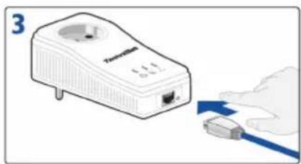
natural_image
Illustration of a TechniSat power plug with a blue cable, no text or symbols present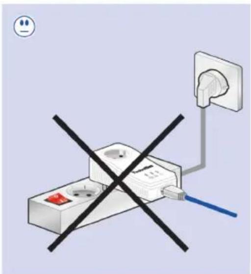
2.1 Scope of delivery 18
2.2 System requirements 18
2.2.1 Operating systems 18
2.2.2 Hardware requirements 18
2.3 Functions 19
2.3.1 Control lights (LEDs) 19
2.3.2 Connections 20
2.4 Connecting the TechniSat PowerLine Webcast 2 20
3 Security in the TechniSat PowerLine 21 Webcast 2 network
4 Appendix 23
4.1 Optimising bandwidth 23
4.2 Important safety instructions 24
4.3 Service information 24
4.4 Technical data 25
1 TechniSat PowerLine Webcast 2
The TechniSat PowerLine Webcast 2 is an optimal solution for installing a home network using the existing power network - with no need for extensive and expensive cabling. Implementing the system is quick and easy, and access speeds similar to those of LAN technology can be achieved.
flowchart
graph TD
    subgraph PowerLine
        A["PowerLine"] --> B["IP Phone"]
        B --> C["PowerLine"]
        C --> D["Laptop"]
        D --> E["Notebook"]
        F["PowerLine"] --> G["PC"]
        G --> H["PowerLine"]
        H --> I["Set-Top-Box & TV"]
        J["PowerLine"] --> K["Internet"]
    end
    style PowerLine fill:#f9f,stroke:#333
    style IP Phone fill:#ccf,stroke:#333
    style Notebook fill:#cfc,stroke:#333
    style PC fill:#fcc,stroke:#333
    style Set-Top-Box & TV fill:#fcf,stroke:#333
    style Internet fill:#cff,stroke:#333
1.1 How the TechniSat PowerLine Webcast 2 works
The TechniSat PowerLine Webcast 2 uses the existing mains power network to transfer data between different computers or network components. This is done by plugging PowerLine adapters into existing power outlets in order to establish a network connection via the building's internal power supply. The adapter modulates the signal and sends it to the next adapter via the mains cabling. The signal is then reconverted and forwarded to the PC or network components.
The process ensures that the mains network and data network do not interfere with each other. Password encryption of data in the network prevents third parties from logging in.
1.2 Saving energy
When integrated PCs or connected devices are switched off, the integrated, patented power saving mode of the TechniSat 200 Mbit/s adapters automatically reduces energy consumption across the PowerLine Webcast 2 network by 65 percent.
In the event that the user forgets to manually switch connected devices to standby mode, the energy saving function will still be triggered. The network card for the computer connected to the TechniSat PowerLine Webcast 2 adapter must be inactive for this to work.
To allow the power saving mode to be enabled for network cards that remain active even when the computer is switched off, we recommend using a multiple socket with an on/off switch.
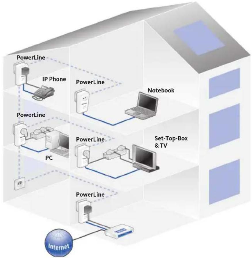
Below are examples of possible uses for the system in office and home networks.
1.3 Usage examples
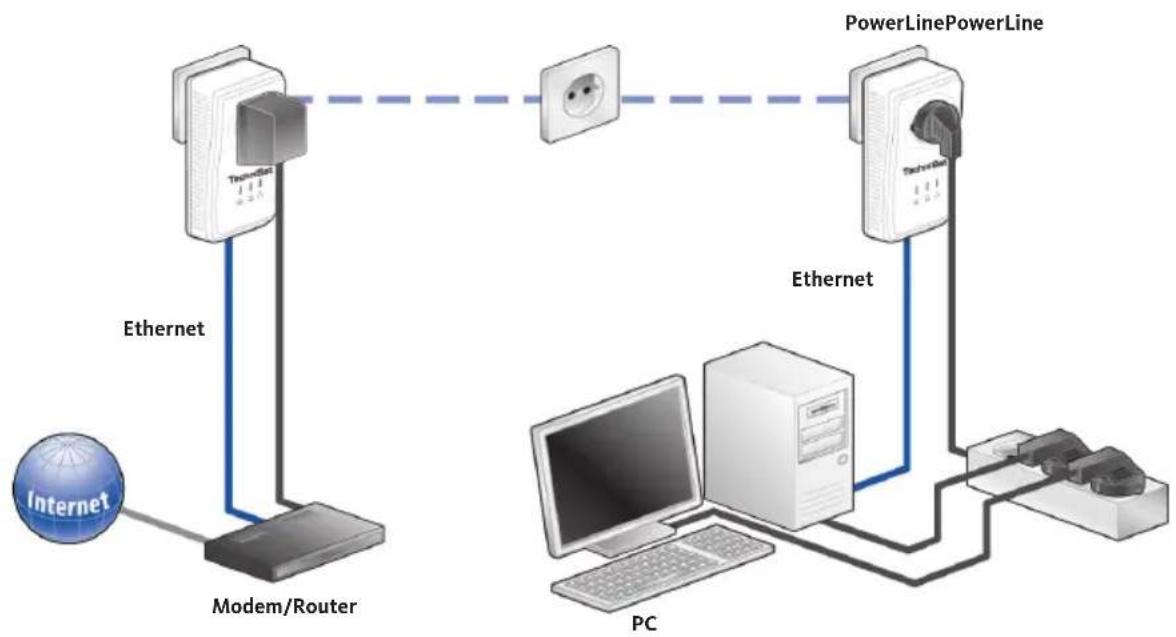
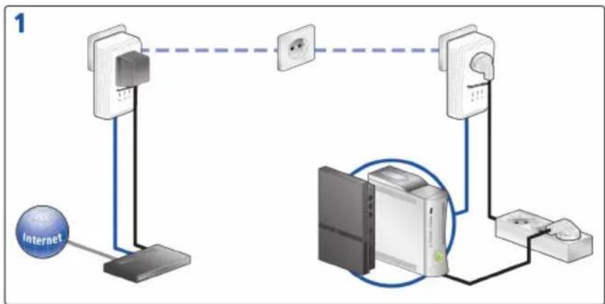
Work station with Internet connection via a DSL modem or router.
1.3.1 Stand-alone Internet solution
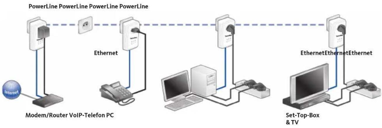
Networking an Internet telephone and a high-speed Internet and IPTV application with an
flowchart
graph TD
    A["Internet"] --> B["Modem/Router"]
    B --> C["PowerLine"]
    C --> D["PC"]
    D --> E["Internet"]
    B --> F["Ethernet"]
    F --> G["Modem/Router"]
    G --> H["PowerLine"]
    H --> I["PC"]
    I --> J["Internet"]
    style A fill:#f9f,stroke:#333
    style B fill:#ccf,stroke:#333
    style C fill:#cfc,stroke:#333
    style D fill:#fcc,stroke:#333
    style E fill:#cff,stroke:#333
    style F fill:#ffc,stroke:#333
    style G fill:#cfc,stroke:#333
    style H fill:#cfc,stroke:#333
    style I fill:#fcc,stroke:#333
    style J fill:#ffc,stroke:#333
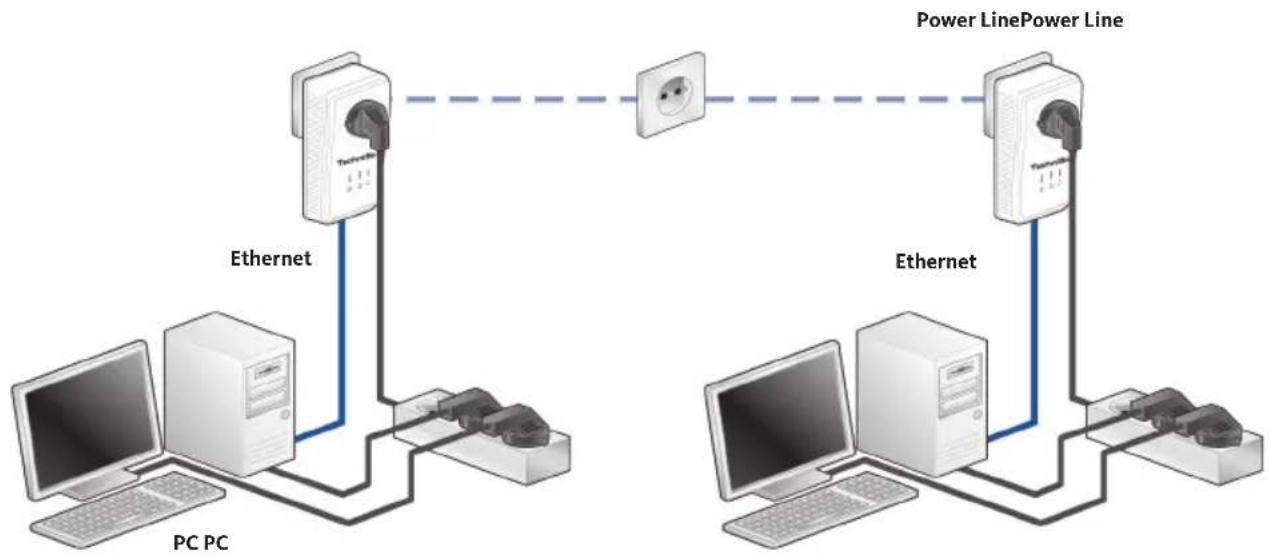
1.3.2 Networking two computers
flowchart
graph TD
    A["PC PC"] -->|Ethernet| B["Server"]
    B --> C["PC"]
    B --> D["Computer"]
    E["Power Line"] --> F["Switch"]
    G["Power Line"] --> H["Switch"]
    I["Power Line"] --> J["Switch"]
    K["Power Line"] --> L["Switch"]
    M["Power Line"] --> N["Switch"]
    O["Power Line"] --> P["Switch"]
    Q["Power Line"] --> R["Switch"]
    S["Power Line"] --> T["Switch"]
    U["Power Line"] --> V["Switch"]
    W["Power Line"] --> X["Switch"]
    Y["Power Line"] --> Z["Switch"]
1.3.3 Multiple-user Internet solution
Internet connection via a DSL modem router.
flowchart
graph LR
    A["Internet"] --> B["Modem/Router VoIP-Telefon PC"]
    B --> C["Ethernet"]
    C --> D["Internet"]
    D --> E["EthernetEthernet"]
    E --> F["Set-Top-Box & TV"]
    F --> G["EthernetEthernetEthernet"]
    G --> H["Internet"]
    style A fill:#f9f,stroke:#333
    style B fill:#ccf,stroke:#333
    style C fill:#cfc,stroke:#333
    style D fill:#fcc,stroke:#333
    style E fill:#cff,stroke:#333
    style F fill:#ffc,stroke:#333
    style G fill:#fcf,stroke:#333
2 Implementation
This section contains everything you need to know about implementing your TechniSat PowerLine Webcast 2. Besides a functional description, you will be taken through the steps for connecting the hardware.
2.1 Scope of delivery
Prior to implementing the system, please check that everything has been supplied. The following components are supplied by TechniSat in this pack:
- 2 x TechniSat PowerLine Webcast 2
- 2 x network cables
- Hard copy of fast start installation guide
TechniSat reserves the right to amend the scope of delivery without prior notice.
2.2 System requirements
The TechniSat PowerLine Webcast 2 is ideal for installing with the following operating systems/hardware:
2.2.1 Operating systems
- Windows XP (32 bit)
· Windows Vista (32/64 bit) - Windows 7 (32/64 bit)
- Linux
• Mac OS X - Any network-enabled operating system.
2.2.2 Hardware requirements
- Network connection. Please ensure that your computer or device has a network card or network adapter with a network interface.
2.3 Functions
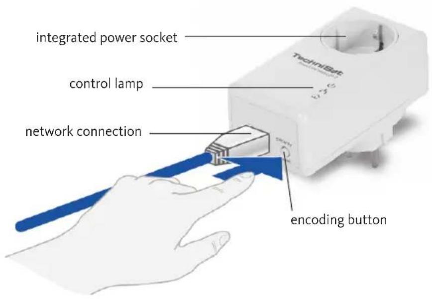
The TechniSat PowerLine Webcast 2 has three control lights (LEDs). Furthermore, the device is equipped with an integrated socket, a network connection and an encryption button.
2.3.1 Control lights (LEDs)


| PWR Off the | device is turned off | |
| On the device is turned on | ||
| It fl ashes the device is in the low consumption mode | ||
| ETH Off no LAN connection | ||
| On existing LAN connection | ||
| It fl ashes data transmission through LAN interface | ||
| Data Off no connection to Powerline network | ||
| On existing Powerline connection | ||
| It fl ashes data transmission through Powerline network | ||
2.3.2 Connections
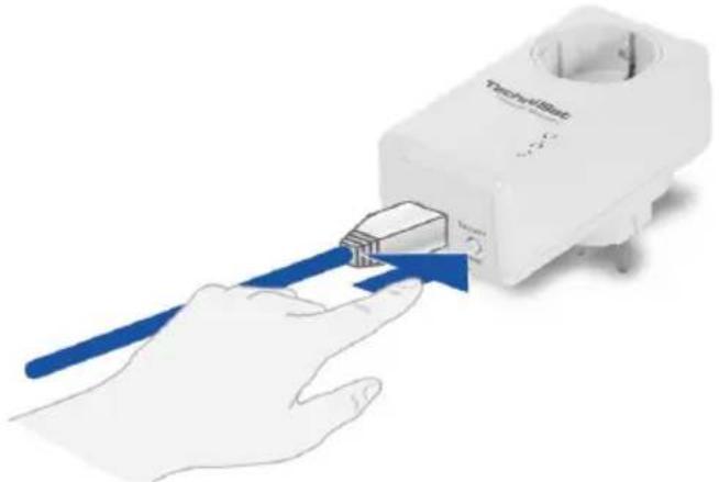
- Network connection: The TechniSat PowerLine Webcast 2 is connected to a computer or another network device via the network cable supplied.
- Integrated socket: If you are connecting additional network devices via a multiple socket, insert this multiple socket into the socket on the PowerLine Webcast 2. The built-in network filter will remove any noise from connected devices and considerably improve data transfer in the home network.
- Encryption button: Data encryption at the push of a button: To see how the encryption button works, please see section 3 „Security in the TechniSat PowerLine Webcast 2 network“.
- Please note that every TechniSat PowerLine Webcast 2 device that needs to be connected to your network should also be connected to the mains network. The TechniSat PowerLine Webcast 2 quickly reverts to standby mode if no enabled network device (e.g. computer) is connected to the network interface. In standby mode the TechniSat PowerLine Webcast 2 cannot be accessed via the mains network.
As soon as a network device (e.g. computer) connected to the network interface is switched back on, your TechniSat PowerLine Webcast 2 can again be accessed via the mains network.
2.4. Connecting the TechniSat PowerLine Webcast 2
The following are instructions and procedures for connecting the TechniSat PowerLine Webcast 2 to a computer or network during installation.
Connecting hardware components involves three steps:
| 1 Use | the network cable provided to attach the TechniSat PowerLine Webcast 2 to a network connection on your (switched on) computer or to another network device. |
| 2 Plug | the TechniSat PowerLine Webcast 2 into a wall socket. |
| 3 Additional network devices attached using a multiple socket can be integrated into the mains supply network by plugging the multiple socket into the socket integrated into the TechniSat PowerLine Webcast 2. | |
As soon as you have connected a minimum of two TechniSat PowerLine Webcast 2 adapters as described in sections 1 and 2, the TechniSat PowerLine Webcast 2 network is ready for use.
3 Security in the TechniSat PowerLine Webcast 2 network
To protect your privacy within the TechniSat PowerLine Webcast 2 network, the system has a function for encrypting data transferred via the mains power supply at the push of a button. TechniSat PowerLine Webcast 2 data encryption can be quickly and safely launched at the push of a button without installing any additional software. To do this, just use the encryption button on the device.
natural_image
Illustration of a hand inserting a device into a white electronic device (no text or symbols visible)Note: No configuration is possible in standby mode

natural_image
Illustration of a device with blue arrows pointing to a paper sheet, no text or symbols present
natural_image
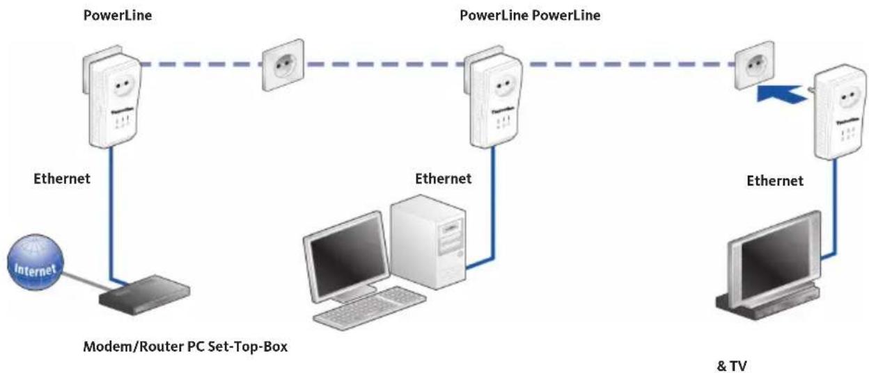
Illustration of a WiFi router connected to a plug, with a blue arrow indicating power flow (no text or symbols)① Encryption of new simple network with two TechniSat PowerLine Webcast 2 adapters.
After you have successfully connected both TechniSat PowerLine Webcast 2 adapters, press each encryption button (hold for 2 seconds). And that's it! Your TechniSat PowerLine Webcast 2 network is now protected against unauthorised access.
② Adding a new TechniSat PowerLine Webcast 2 to an existing TechniSat PowerLine Webcast 2 network
flowchart
graph LR
    A["Internet"] --> B["Modem/Router PC Set-Top-Box"]
    B --> C["PowerLine"]
    C --> D["PowerLine PowerLine"]
    D --> E["+"]
    E --> F["+"]
    F --> G["+"]
    G --> H["+"]
    H --> I["+"]
    I --> J["+"]
    J --> K["+"]
    K --> L["+"]
    L --> M["+"]
    M --> N["+"]
    N --> O["+"]
    O --> P["+"]
    P --> Q["+"]
    Q --> R["+"]
    R --> S["+"]
    S --> T["+"]
    T --> U["+"]
    U --> V["+"]
    V --> W["+"]
    W --> X["+"]
    X --> Y["+"]
    Y --> Z["+"]
    Z --> AA["+"]
    AA --> AB["+"]
    AB --> AC["+"]
    AC --> AD["+"]
    AD --> AE["+"]
    AE --> AF["+"]
    AF --> AG["+"]
    AG --> AH["+"]
    AH --> AI["+"]
    AI --> AJ["+"]
    AJ --> AK["+"]
    AK --> AL["+"]
    AL --> AM["+"]
    AM --> AN["+"]
    AN --> AO["+"]
    AO --> AP["+"]
    AP --> AQ["+"]
    AQ --> AR["+"]
    AR --> AS["+"]
    AS --> AT["+"]
    AT --> AU["+"]
    AU --> AV["+"]
    AV --> AW["+"]
    AW --> AX["+"]
    AX --> AY["+"]
If your existing TechniSat PowerLine Webcast 2 network has already been secured using the encryption button, proceed as follows to integrate additional adapters. After you have successfully connected the new TechniSat PowerLine Webcast 2, you have to press firstly the encryption button (and hold for 2 seconds) on an adapter in your existing network, then the encryption button on the new TechniSat PowerLine
Webcast 2 (for 2 seconds again). And that's it! The new TechniSat PowerLine Webcast 2 is now integrated into your network.
To integrate additional TechniSat PowerLine Webcast 2 adapters into your network, repeat the process described above.
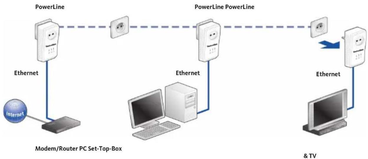
③ Removing a TechniSat PowerLine Webcast 2 from the network.
flowchart
graph LR
    A["Internet"] --> B["Modem/Router PC Set-Box"]
    B --> C["PowerLine"]
    C --> D["PowerLine PowerLine"]
    D --> E["+"]
    B --> F["Ethernet"]
    C --> G["Ethernet"]
    D --> H["Ethernet"]
    E --> I["+"]
    F --> J["Ethernet"]
    G --> K["Ethernet"]
    H --> L["+"]
    I --> M["+"]
    J --> N["+"]
    K --> O["+"]
    L --> P["& TV"]
    M --> P
    N --> P
To remove a TechniSat PowerLine Webcast 2 from an existing network, press and hold the encryption button on the relevant adapter for at least 3 seconds. This device receives a new random password and is therefore excluded from your network. To reintegrate it into another TechniSat PowerLine Webcast 2 network, follow the procedure described in ① or ②, depending on whether you are setting up a new network or enhancing an existing one.
4 Appendix
4.1 Optimising bandwidth
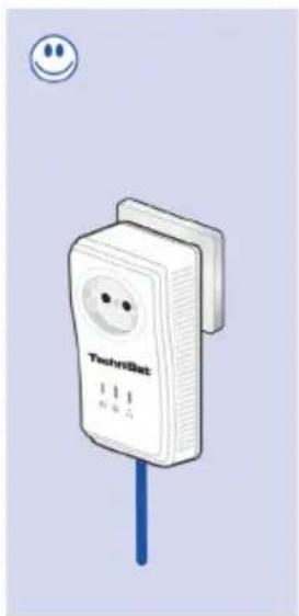
To significantly improve transfer performance across the network, we recommend observing the following connection rules:
Insert the device directly into a wall socket; do not use a multiple socket.
natural_image
Illustration of a white SmartGrid device with a blue cable and a smiley face icon (no text or symbols on the device itself)
Other network devices connected using a multiple socket should be connected to the mains supply network via the socket integrated into the TechniSat PowerLine Webcast 2. Always plug the multiple socket into the socket on the TechniSat PowerLine Webcast 2. This improves data transfer across the home network and makes optimum use of the TechniSat PowerLine Webcast 2 filter function.
Note: If additional devices need a power supply, use a separate wall socket.
4.2 Important safety instructions
All safety and operating instructions should be read and understood before installing the device and then kept for future reference.
- The device should not be opened. There are no components inside the device that need maintaining by the user.
- Do not try to maintain the product yourself. Always contact a qualified professional for any maintenance work. Beware of electric shock!
- Only use the device in a dry location.
· Always use the network cable supplied to connect the device.
- Do not insert objects into the device's apertures.
- To disconnect the device from the power network, pull out the mains plug.
- Do not place the device in direct sunlight.
- Slits and apertures in the housing are for ventilation and should not be blocked or covered.
- The device should not be located close to a source of heat.
- The device should only be located in places that have sufficient ventilation in accordance with the manufacturer's instructions.
- Disconnect the device from the mains before cleaning. When cleaning the device, never use water, thinner, benzene, alcohol or other corrosive cleaners, as these can cause damage to the housing. Simply use a damp cloth.
- The device should only be used with a mains power supply as described on the label.
- In the event of damage, disconnect the device from the mains and contact your customer service provider. Damage can occur in the following cases:
- If the power cable or plug is damaged.
- If water has been spilled on the device or if foreign objects have found their way into it.
- If the device has been exposed to rain or water.
- If the device is not working even though all operating instructions have been properly followed.
- If the device housing is damaged.
4.3 Service information
This product is quality-tested and provided with the legal warranty period of 24 months from the date of purchase. Please keep your invoice as proof of purchase.
Attention!
If it should have come to any problems with this device, please contact our technical support hotline
Mo - Fr from 8:00 a.m. to 20:00 p.m.
+49 (0)3925/92201800
For a possibly required returning of the product please use the following address only:
| Protocols TCP/IP, IGMP, CSMA/CA, QoS | |
| Transfer speed 200 Mbit/s | |
| Modulation OFDM (1024/256/64/16-QAM,QPSK,BPSK and ROBO modulation technology) | |
| Data path Ethernet <-> mains network | |
| Range Max. 300m via mains network | |
| Security 128-bit AES encryption via mains network(activated via pushbutton) | |
| LEDs Power | Ethernet (Link/Act)PowerLine Webcast 2 (Link/Act) |
| Socket/Connector DE, NL, ES, PT, AT, SW, FI, NO:Type F (CEE 7/4)/Type E + F (CEE 7/7 + CEE 7/4)FR, BE: Type E (US/UK 7/7)/Type E + F (CEE 7/7 + CEE 7/4) | |
| Device connection Ethernet RJ45 | |
| Power consumption < 3Watt (normal) | <1Watt (energy saving function) |
| Voltage supply AC 100 - 240V~ 50/60Hz | |
| Attenuation filter 2 - 30 MHz | |
| Temperature Storage: -20°C - 70°C | Operation: 0°C - 40°C |
| Adapter dimensions | 112 x 56 x 49mm (height x width x depth) |
| Ambient conditions | 10-90% humidity (non-condensing) |
| System requirements | Ethernet interface,Operating systems includingWindows® (XP32bit),Windows® Vista (32/64bit),Windows®7 (32/64bitLinux®Mac OS® Xand all TCP/IP operating systems |
| Approvals | CE-compliant in accordance with technical requirements for all EU countries plus Switzerland:EN 55022:2006, EN 50412-2-1:2006, EN 60950-1:2006 |
Contenu
1 TechniSat PowerLine Webcast 2 27
natural_image
Illustration of a hand holding a medical device with a blue arrow pointing to it, no text or symbols present.natural_image
Illustration of a medical device with blue arrows indicating insertion or release process (no text or symbols)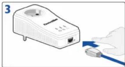
natural_image
Illustration of a WiFi router connected to a USB cable (no text or symbols visible)① comprenant 2 adaptateurs TechniSat PowerLine Webcast 2.
natural_image
Illustration of a TechniSat power plug with a blue cable, no text or symbols present
- TechniSat
- Inhalt
- TechniSat PowerLine Webcast 2 3
- Security in the TechniSat PowerLine 21 Webcast 2 network
- Appendix 23
- TechniSat PowerLine Webcast 2
- How the TechniSat PowerLine Webcast 2 works
- Saving energy
- Usage examples
- Stand-alone Internet solution
- Networking two computers
- Multiple-user Internet solution
- Implementation
- Scope of delivery
- System requirements
- Operating systems
- Hardware requirements
- Functions
- Control lights (LEDs)
- Connections
- Connecting the TechniSat PowerLine Webcast 2
- Security in the TechniSat PowerLine Webcast 2 network
- Appendix
- Optimising bandwidth
- Important safety instructions
- Service information
- Contenu
- TechniSat PowerLine Webcast 2 27
Brand : TECHNISAT
Model : PowerLine Webcast 2
Category : Powerline Adapter