BFT123F - Screwdriver MAKITA - Free user manual and instructions
Find the device manual for free BFT123F MAKITA in PDF.

Frequently Asked Questions - BFT123F MAKITA
User questions about BFT123F MAKITA
0 question about this device. Answer the ones you know or ask your own.
Ask a new question about this device
Download the instructions for your Screwdriver in PDF format for free! Find your manual BFT123F - MAKITA and take your electronic device back in hand. On this page are published all the documents necessary for the use of your device. BFT123F by MAKITA.
USER MANUAL BFT123F MAKITA
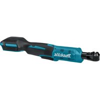
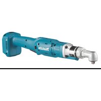
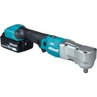
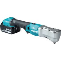
GB Cordless Screwdriver Instruction Manual
natural_image
Line drawing of a handheld electric drill press (no text or symbols)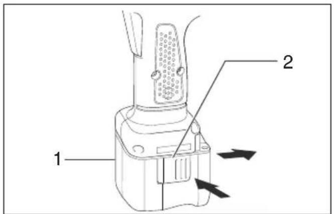
text_image
Technical diagram of a walkie-talkie with labeled parts and directional arrows indicating movement or force.1
text_image
Technical diagram of a mechanical device with numbered parts and directional arrows indicating movement or force.2
other
| Color | Value Range | | :--- | :--- | | (C) E F | 4 | | (C) E F | 5 | | E | 4 | | E | 5 | | F | 4 | | F | 5 | | orange | 0% - 10% | | orange | 10% - 40% | | orange | 40% - 60% | | orange | 60% - 80% | | orange | 80% - 100% |3
text_image
64
text_image
A 7 B5
text_image
86
text_image
Technical line drawing of a camera with labeled parts and numbered annotation7
text_image
10 118
text_image
10 11 12 13 14 15 169
text_image
12 mm (15/32") 9 mm (3/8")10
text_image
17 1811 12
natural_image
Line drawing of a hand operating a handheld electric drill press (no text or symbols present)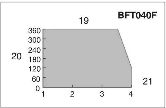
area
| x | y | |---|---| | 1 | 20 | | 4 | 21 | | 3 | 19 |
bar
| Category | Value | |---|---| | BFT020F | 19 | | BFT021F | 21 |13 14
area
BFT042F | Category | Value | |---|---| | 1 | 360 | | 2 | 19 | | 3 | 21 | | 4 | 20 |15 16
area
| x | y | |---|---| | 3 | 0 | | 4 | 19 | | 5 | 20 | | 6 | 360 | | 7 | 180 | | 8 | 60 | BFT080F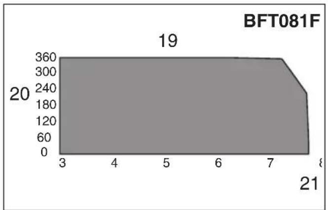
area
| x | y | |----|-----| | 3 | 20 | | 4 | 20 | | 5 | 20 | | 6 | 20 | | 7 | 20 | | 8 | 19 | | 9 | 19 | | 10 | 19 | | 11 | 19 | | 12 | 19 | | 13 | 19 | | 14 | 19 | | 15 | 19 | | 16 | 19 | | 17 | 19 | | 18 | 19 | | 19 | 19 | | 20 | 19 | | 21 | 19 |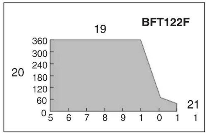
17 18
bar
| X | Y | |----|-----| | 1 | 360 | | 2 | 20 | | 3 | 0 | | 4 | 0 | | 5 | 0 | | 6 | 0 | | 7 | 0 | | 8 | 0 | | 9 | 0 | | 10 | 0 | | 11 | 0 | | 12 | 0 | | 13 | 0 | | 14 | 0 | | 15 | 0 | | 16 | 0 | | 17 | 0 | | 18 | 0 | | 19 | 0 | | 20 | 0 | | 21 | 0 |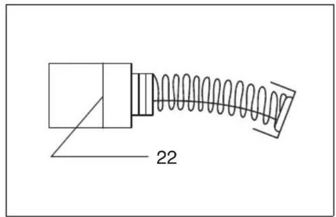
text_image
2219 20
text_image
23 2421
ENGLISH (Original instructions)
| Explanation of general view | ||
| 1 Battery cartridge | 9 LED indicator | 17 Bit |
| 2 Button | 10 Adjusting ring | 18 Sleeve |
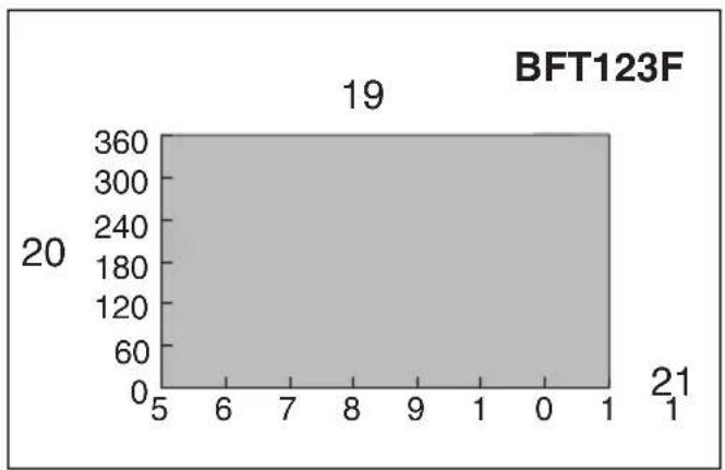
| 3 Red part | 11 Ring | 19 Range of fastening capacity |
| 4 Indicating lamp | 12 Scale | 20 Revolution angle (°) |
| 5 Capacity | 13 Adjusting grip | 21 Torque (N•m) |
| 6 Switch trigger | 14 Hole for adjusting grip | 22 Limit mark |
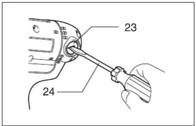
| 7 Reversing switch lever | 15 Yellow line | 23 Brush holder cap |
| 8 Front lamp | 16 Compression spring | 24 Screwdriver |
SPECIFICATIONS
| Model BFT020F | BFT021F | BFT040F | BFT080F | BFT122F | BFT042F | BFT081F | BFT123F | ||
| Fastening torque (N•m) | Hard joi | nt 0.5- | 2 0.5-2 | 1-4 3-8 | 5-12 1 | -4 3-8 | 5-12 | ||
| Soft joint | 0.5-2 | 0.5-2 | 1-3.5 | 3-6.5 | 5-10 | 1-3.5 | 3-7.5 | 5-12 | |
| No load speed (min-1) | 540 | 320 | 950 | 540 | 320 | 1,200 | 700 | 390 | |
| Dimensions | 200 x 65 x 251 mm(with Battery Cartridge BH9020/BH9020A) | 200 x 71 x 242 mm(with Battery Cartridge BH1220C) | |||||||
| 200 x 65 x 274 mm(with Battery Cartridge BH9033/BH9033A) | 200 x 71 x 251 mm(with Battery Cartridge BH1233C) | ||||||||
| Net weight | 1.4 kg | 1.5 kg | |||||||
| Rated voltage | D.C. 9.6 V | D.C. 12 V | |||||||
- Due to our continuing program of research and development, the specifications herein are subject to change without notice.
- Specifications and battery cartridge may differ from country to country.
- Weight, with battery cartridge, according to EPTA-Procedure 01/2003
ENE033-1
Intended use
The tool is intended for screw driving in wood, metal and plastic.
ENF002-1
Power supply
The tool should be connected only to a power supply of the same voltage as indicated on the nameplate, and can only be operated on single-phase AC supply. They are double-insulated in accordance with European Standard and can, therefore, also be used from sockets without earth wire.
GEA010-1
General Power Tool Safety Warnings
⚠ WARNING Read all safety warnings and all instructions. Failure to follow the warnings and instructions may result in electric shock, fire and/or serious injury.
Save all warnings and instructions for future reference.
GEB050-2
- Hold power tool by insulated gripping surfaces, when performing an operation where the fastener may contact hidden wiring. Fasteners contacting a "live" wire may make exposed metal parts of the power tool "live" and could give the operator an electric shock.
- Always be sure you have a firm footing. Be sure no one is below when using the tool in high locations.
- Hold the tool firmly.
- Keep hands away from rotating parts.
- Do not touch the bit or the workpiece immediately after operation; they may be extremely hot and could burn your skin.
SAVE THESE INSTRUCTIONS.
WARNING:
DO NOT let comfort or familiarity with product (gained from repeated use) replace strict adherence to safety rules for the subject product. MISUSE or failure to follow the safety rules stated in this instruction manual may cause serious personal injury.
IMPORTANT SAFETY INSTRUCTIONS
FOR BATTERY CARTRIDGE
- Before using battery cartridge, read all instructions and cautionary markings on (1) battery charger, (2) battery, and (3) product using battery.
- Do not disassemble battery cartridge.
- If operating time has become excessively shorter, stop operating immediately. It may result in a risk of overheating, possible burns and even an explosion.
- If electrolyte gets into your eyes, rinse them out with clear water and seek medical attention right away. It may result in loss of your eyesight.
- Do not short the battery cartridge:
(1) Do not touch the terminals with any conductive material.
(2) Avoid storing battery cartridge in a container with other metal objects such as nails, coins, etc.
(3) Do not expose battery cartridge to water or rain.
A battery short can cause a large current flow, overheating, possible burns and even a breakdown.
- Do not store the tool and battery cartridge in locations where the temperature may reach or exceed 50^ C ( 122^ F).
- Do not incinerate the battery cartridge even if it is severely damaged or is completely worn out. The battery cartridge can explode in a fire.
- Be careful not to drop or strike battery.
- Do not use dropped or struck battery.
SAVE THESE INSTRUCTIONS.
Tips for maintaining maximum battery life
- Charge the battery cartridge before completely discharged. Always stop tool operation and charge the battery cartridge when you notice less tool power.
- Never recharge a fully charged battery cartridge. Overcharging shortens the battery service life.
- Charge the battery cartridge with room temperature at 10^ C – 40^ C ( 50^ F – 104^ F). Let a hot battery cartridge cool down before charging it.
- Charge the Nickel Metal Hydride battery cartridge when you do not use it for more than six months.
FUNCTIONAL DESCRIPTION
CAUTION:
- Always be sure that the tool is switched off and the battery cartridge is removed before adjusting or checking function on the tool.
Installing or removing battery cartridge
- Always switch off the tool before insertion or removal of the battery cartridge.
For Models BFT020F, BFT021F, BFT040F, BFT080F, BFT122F (Fig. 1)
- To remove the battery cartridge, withdraw it from the tool while pressing the buttons on both sides of the cartridge.
- To insert the battery cartridge, align the tongue on the battery cartridge with the groove in the housing and slip it into place. Always insert it all the way until it locks in place with a little click. If not, it may accidentally fall out of the tool, causing injury to you or someone around you.
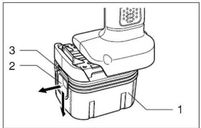
For Models BFT042F, BFT081F, BFT123F (Fig. 2)
- To remove the battery cartridge, withdraw it from the tool while sliding the button on the front of the cartridge.
- To insert the battery cartridge, align the tongue on the battery cartridge with the groove in the housing and slip it into place. Always insert it all the way until it locks in place with a little click. If you can see the red part on the upper side of the button, it is not locked completely. Insert it fully until the red part cannot be seen. If not, it may accidentally fall out of the tool, causing injury to you or someone around you.
- Do not use force when inserting the battery cartridge. If the cartridge does not slide in easily, it is not being inserted correctly.
Refresh charging
Refreshing battery adapter (optional accessory) can refresh an inactive battery cartridge.
- Refresh charging should be done once a week.
- When you charge a new battery cartridge or a battery cartridge that has not been used for a long time, it may not accept a full charge. In this case, refresh charging must be done. The battery cartridge may decrease the tool performance, because the chemical substance of the battery cartridge is inactive.
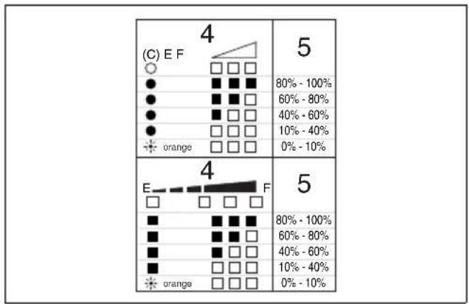
Checking the remaining battery capacity (Fig. 3)
For BH9020A, BH9033A
When charging
When the charging begins, the first (far left) indicating lamp begins to flicker. Then, as charging proceeds, the other lamps light, one after the other, to indicate the battery capacity.
When using
When the tool is switched on, the lamps will light after 2 seconds to indicate the remaining battery capacity. When the tool is switched off, the light goes out. If the battery has not been used for a long time, or is needed refresh charging, the orange lamp begins to flicker. Use Makita refreshing adapter to refresh the battery.
CAUTION:
- A battery cartridge extracted from the charger that has been unplugged with the battery cartridge inserted does not indicate the battery capacity due to its protective function even if the tool is switched on after the battery insertion into the tool.
At this time, recharge it for about five seconds before use.
NOTE:
- Please contact Makita Authorized Service Center if the warning lamp of the battery cartridge does not light up when using or charging.
Switch action (Fig. 4)
CAUTION:
- Before inserting the battery cartridge into the tool, always check to see that the switch trigger actuates properly and returns to the "OFF" position when released.
To start the tool, simply pull the switch trigger. Release the switch trigger to stop.
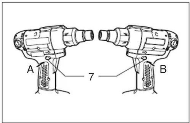
Reversing switch action (Fig. 5)
CAUTION:
- Always check the direction of rotation before operation.
- Use the reversing switch only after the tool comes to a complete stop. Changing the direction of rotation before the tool stops may damage the tool.
- When not operating the tool, always set the reversing switch lever to the neutral position.
This tool has a reversing switch to change the direction of rotation. Depress the reversing switch lever from the A side for clockwise rotation or from the B side for counterclockwise rotation.
When the reversing switch lever is in the neutral position, the switch trigger cannot be pulled.
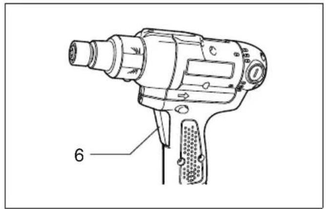
Lighting up the lamps (Fig. 6)
CAUTION:
- Do not look in the light or see the source of light directly.
Pull the switch trigger to light up the lamp. The lamp keeps on lighting while the switch trigger is being pulled. The light automatically goes out 10 seconds after the switch trigger is released.
NOTE:
- Use a dry cloth to wipe the dirt off the lens of lamp. Be careful not to scratch the lens of lamp, or it may lower the illumination.
LED indicator (Fig. 7)
The lamp on the tool shows the following functions.
| Function Status | Status of the LED indicator/beeper | Action to be taken | ||
| LED indicator | Beeper | |||
| Auto-stop fastening | This function works when the tool has reached the preset fastening torque and normal tightening has been completed. This helps overtightening to be avoided. | Lights up in green for approximately one second. | — — | |
| Delayed re-start | For approximately one second after auto-stop fastening, the tool does not start even if the switch trigger is pulled. | |||
| Warning against insufficient fastening | Insufficient fastening has been performed when the switch trigger has released before reaching the preset fastening torque. | Lights up in red. | A long beep | Retighten the screw. |
| Warning for battery cartridge capacity | This indicates the appropriate time to replace the battery cartridge when the battery power becomes low. | Flickers in red slowly. | A series of long beeps | Replace the battery with fully charged one. |
| Checking the remaining battery capacity, Autostop | This function works when the battery power is almost used up. At this time, tool stops immediately. | Lights up in red. | A long beep | Replace the battery with fully charged one. |
| Check the LED indicator, light and beeper operation | This function works to check the proper operation of the LED indicator, light and beeper when a battery cartridge has been inserted into the tool. | Lights up first in green, next red.(And then the light comes on.) | A series of very short beeps | — |
| Anti-reset of controller | This function works when an abnormal drop of the battery voltage occurs for some reason, and the tool stops. | Flickers in red and green alternatively. | A series of short beeps | Replace the battery with fully charged one. |
| Overheat | This function works when the temperature of the controller goes up very highly, and the tool stops. | Flickers in red quickly. | A series of short beeps | Remove the battery cartridge immediately and cool the tool down. |
| Operation error of the switch trigger | This function works to avoid the tool's immediate start upon insertion of battery cartridge into the tool with the switch trigger being pulled. | Flickers in red and green alternatively. | A series of short beeps | Release the switch trigger. |
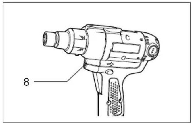
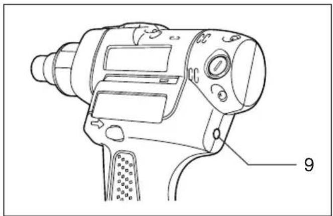
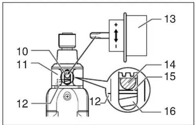
Adjusting the fastening torque (Fig. 8 & 9)
When you wish to drive machine screws, wood screws, hex bolts, etc. with the predetermined torque, adjusting the fastening torque as follows.
- First remove the battery cartridge from the tool.
- Loosen and remove the screw that secures ring.
- Rotate the ring in the front of the tool by hand so that a hole can be seen below the ring.
- Place the battery cartridge in place and pull the switch trigger. Release it so that the adjusting ring rotates and becomes visible in the hole. And then remove the battery cartridge.
- Use an optional adjusting grip to adjust the fastening torque. Insert the pin of the adjusting grip into the hole in the front of the tool. And then, turn the adjusting grip clockwise to set a greater fastening torque, and counterclockwise to set a smaller fastening torque.
- Align the yellow line with your desired number on the fastening torque scale.
- Insert the battery cartridge and be sure that a fastening torque has been set up by using a fastening torque tester.
- Rotate the ring in front of the tool and then tighten the screw to secure the ring.
NOTE:
- Numbers on the fastening torque scale is a guideline to set up your desired fastening torque.
ASSEMBLY
CAUTION:
- Always be sure that the tool is switched off and the battery cartridge is removed before carrying out any work on the tool.
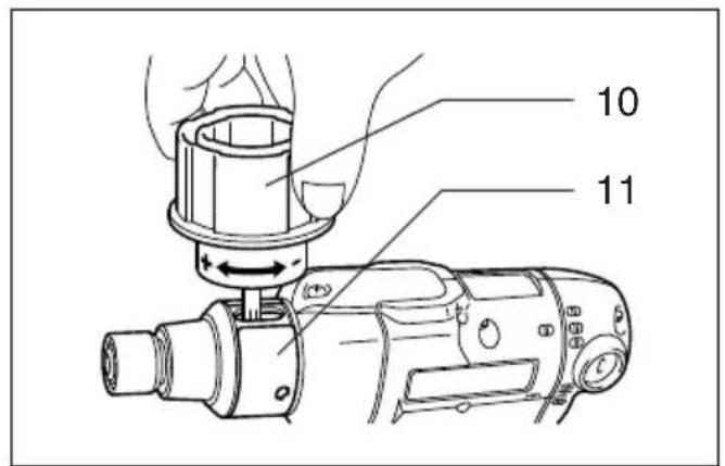
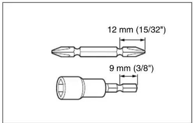
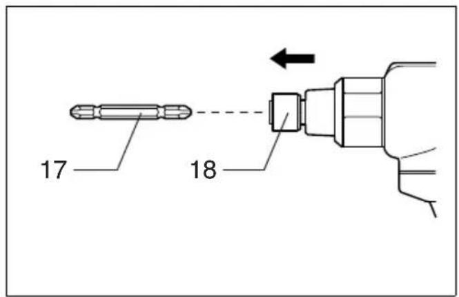
Installing or removing driver bit or socket bit (Fig. 10 & 11)
Use only the driver bit or socket bit shown in the figure. Do not use any other driver bit or socket bit.
To install the bit, pull the sleeve in the direction of the arrow and insert the bit into the sleeve as far as it will go. Then release the sleeve to secure the bit.
To remove the bit, pull the sleeve in the direction of the arrow and pull the bit out firmly.
NOTE:
- If the bit is not inserted deep enough into the sleeve, the sleeve will not return to its original position and the bit will not be secured. In this case, try re-inserting the bit according to the instructions above.
OPERATION
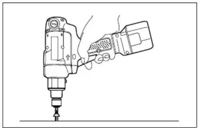
Screwdriving operation (Fig. 12)
Place the point of the driver bit in the screw head and apply pressure to the tool. Then switch the tool on. When the clutch cuts in, the motor will stop automatically. Then release the switch trigger.
NOTE:
- Make sure that the driver bit is inserted straight in the screw head, or the screw and/or bit may be damaged.
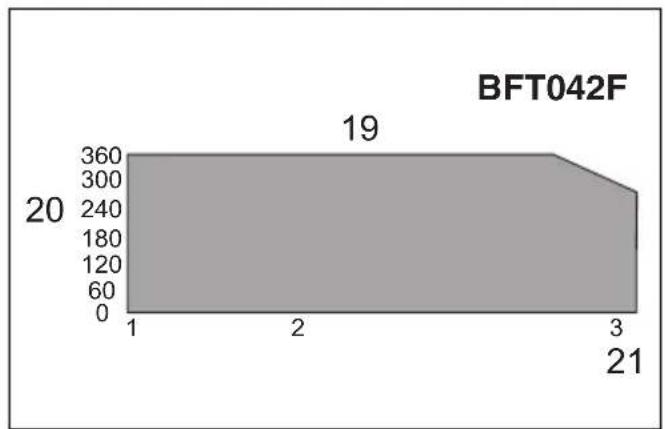
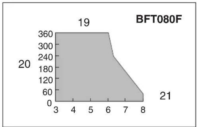
Limits of fastening capacity (Fig. 13, 14, 15, 16, 17, 18, 19)
Use the tool within the limits of fastening capacity. If you use the tool beyond the limits, the clutch does not work. And the tool cannot deliver enough fastening torque.
NOTE:
- The revolution angle means the angle which a screw/bolt revolves when the tool attains to 100% from 50% of desired torque.
- Use of a low temperature conditioned battery cartridge may sometimes give warning for battery cartridge capacity by warning lamp and beeper which makes the tool stop immediately. In this case, the range of fastening capacity may be inferior to those shown in the above even if a charged battery cartridge is used.
MAINTENANCE
CAUTION:
- Always be sure that the tool is switched off and the battery cartridge is removed before attempting to perform inspection or maintenance.
- Never use gasoline, benzine, thinner, alcohol or the like. Discoloration, deformation or cracks may result.
Replacing carbon brushes
Remove and check the carbon brushes regularly. Replace when they wear down to the limit mark. Keep the carbon brushes clean and free to slip in the holders. Both carbon brushes should be replaced at the same time. Use only identical carbon brushes. (Fig. 20)
Use a screwdriver to remove the brush holder caps. Take out the worn carbon brushes, insert the new ones and secure the brush holder caps. (Fig. 21)
To maintain product SAFETY and RELIABILITY, repairs, any other maintenance or adjustment should be performed by Makita Authorized Service Centers, always using Makita replacement parts.
ACCESSORIES
CAUTION:
- These accessories or attachments are recommended for use with your Makita tool specified in this manual. The use of any other accessories or attachments might present a risk of injury to persons. Only use accessory or attachment for its stated purpose.
If you need any assistance for more details regarding these accessories, ask your local Makita Service Center.
- Various type of Makita genuine batteries and chargers
• Automatic refreshing adapter - Adjust grip
- Protector
- Grip Base Set
- Grip 37
- Anti kickback head
Noise
The typical A-weighted noise level determined according to EN60745:
Model BFT020F, BFT021F, BFT040F, BFT042F, BFT080F, BFT081F, BFT122F
Sound pressure level ( L_pA ): 70 dB (A) or less Uncertainty (K): 3 dB (A)
The noise level under working may exceed 80 dB (A) Model BFT123F
Sound pressure level ( L_pA ): 71 dB (A) Uncertainty (K): 3 dB (A)
The noise level under working may exceed 80 dB (A).
Wear ear protection
ENG900-1
Vibration
The vibration total value (tri-axial vector sum) determined according to EN60745:
Work mode: screwdriving without impact Vibration emission ( a_h ): 2.5 m/s ^2 or less Uncertainty (K): 1.5 m/s ^2
ENG901-1
- The declared vibration emission value has been measured in accordance with the standard test method and may be used for comparing one tool with another.
- The declared vibration emission value may also be used in a preliminary assessment of exposure.
WARNING:
- The vibration emission during actual use of the power tool can differ from the declared emission value depending on the ways in which the tool is used.
- Be sure to identify safety measures to protect the operator that are based on an estimation of exposure in the actual conditions of use (taking account of all parts of the operating cycle such as the times when the tool is switched off and when it is running idle in addition to the trigger time).
For European countries only
EC Declaration of Conformity
We Makita Corporation as the responsible manufacturer declare that the following Makita machine(s):
Designation of Machine: Cordless Screwdriver
Model No./ Type: BFT020F, BFT021F, BFT040F,
BFT042F, BFT080F, BFT081F, BFT122F, BFT123F are of series production and
Conforms to the following European Directives: 2006/42/EC
And are manufactured in accordance with the following standards or standardised documents: EN60745
The technical documentation is kept by our authorized representative in Europe who is:
Makita International Europe Ltd.
Michigan Drive, Tongwell,
Milton Keynes, MK15 8JD, England
30.1.2009

Tomoyasu Kato Director
Makita Corporation
3-11-8, Sumiyoshi-cho,
Anjo, Aichi, JAPAN
Descriptif
(Fig. 13, 14, 15, 16, 17, 18, 19)
Modèle BFT020F, BFT021F, BFT040F, BFT042F, BFT080F, BFT081F, BFT122F
Michigan Drive, Tongwell,
Milton Keynes, MK15 8JD, Angleterre
30.1.2009

Für Modelle BFT020F, BFT021F, BFT040F, BFT080F, BFT122F (Abb. 1)
Modell BFT020F, BFT021F, BFT040F, BFT042F, BFT080F, BFT081F, BFT122F
Michigan Drive, Tongwell,
Milton Keynes, MK15 8JD, England
30.1.2009

Tomoyasu Kato Direktor
Makita Corporation
3-11-8, Sumiyoshi-cho,
Anjo, Aichi, JAPAN
Visione generale
Modelli BFT020F, BFT021F, BFT040F, BFT080F, BFT122F (Fig. 1)
(Fig. 13, 14, 15, 16, 17, 18, 19)
Modello BFT020F, BFT021F, BFT040F, BFT042F, BFT080F, BFT081F, BFT122F
Livello pressione sonora ( L_pA ): 70 dB (A) o meno Incertezza (K): 3 dB (A)
Modello No./ Tipo: BFT020F, BFT021F, BFT040F,
BFT042F, BFT080F, BFT081F, BFT122F, BFT123F
Michigan Drive, Tongwell,
Milton Keynes, MK15 8JD, England
30.1.2009

Tomoya su Kato
Amministratore
Makita Corporation
3-11-8, Sumiyoshi-cho,
Anjo, Aichi, JAPAN
(Fig. 13, 14, 15, 16, 17, 18, 19)
Model BFT020F, BFT021F, BFT040F, BFT042F, BFT080F, BFT081F, BFT122F
Geluidsdrukniveau ( L_pA ): 70 dB (A) of lager
Onnauwkeurigheid (K): 3 dB (A)
Modelnr./Type: BFT020F, BFT021F, BFT040F, BFT042F,
BFT080F, BFT081F, BFT122F, BFT123F
Michigan Drive, Tongwell,
Milton Keynes, MK15 8JD, Engeland
30.1.2009

Tomoyasu Kato
Directeur
Makita Corporation
3-11-8, Sumiyoshi-cho,
Anjo, Aichi, JAPAN
(Fig. 13, 14, 15, 16, 17, 18, 19)
Modelo BFT020F, BFT021F, BFT040F, BFT042F, BFT080F, BFT081F, BFT122F
BFT042F, BFT080F, BFT081F, BFT122F, BFT123F
Michigan Drive, Tongwell,
Milton Keynes, MK15 8JD, Inglaterra
30.1.2009

Tomoyasu Kato
Director
Makita Corporation 3-11-8, Sumiyoshi-cho, Anjo, Aichi, JAPAN
Explicação geral
Para os Modelos BFT020F, BFT021F, BFT040F, BFT080F, BFT122F (Fig. 1)
Acender as lâmpadas (Fig. 6)
PRECAUÇÃO:
Modelo BFT020F, BFT021F, BFT040F, BFT042F, BFT080F, BFT081F, BFT122F
Michigan Drive, Tongwell,
Milton Keynes, MK15 8JD, Inglaterra
30.1.2009

Tomoyasu Kato
Director
Makita Corporation
3-11-8, Sumiyoshi-cho,
Anjo, Aichi, JAPAN
For model BFT020F, BFT021F, BFT040F, BFT080F, BFT122F (Fig. 1)
For model BFT042F, BFT081F, BFT123F (Fig. 2)
(Fig. 13, 14, 15, 16, 17, 18, 19)
Model BFT020F, BFT021F, BFT040F, BFT042F, BFT080F, BFT081F, BFT122F
Michigan Drive, Tongwell,
Milton Keynes, MK15 8JD, England
30.1.2009

Modell BFT020F, BFT021F, BFT040F, BFT042F, BFT080F, BFT081F, BFT122F
BFT080F, BFT081F, BFT122F, BFT123F
Michigan Drive, Tongwell,
Milton Keynes, MK15 8JD, England
30.1.2009

3-11-8, Sumiyoshi-cho,
Anjo, Aichi, JAPAN
For modellene BFT020F, BFT021F, BFT040F, BFT080F, BFT122F (Fig. 1)
(Fig. 13, 14, 15, 16, 17, 18, 19)
Modell BFT020F, BFT021F, BFT040F, BFT042F, BFT080F, BFT081F, BFT122F
Lydtrykknivå (LpA): 70 dB (A) eller mindre Usikkerhet (K): 3 dB (A)
Under bruk kan støynivået overskride 80 dB (A)
Modell BFT123F
Michigan Drive, Tongwell,
Milton Keynes, MK15 8JD, England
30.1.2009

Tomoyasu Kato
Direktor
Makita Corporation
3-11-8, Sumiyoshi-cho,
Anjo, Aichi, JAPAN
Yleisselostus
Mallit BFT020F, BFT021F, BFT040F, BFT080F, BFT122F (Kuva 1)
Malli BFT020F, BFT021F, BFT040F, BFT042F, BFT080F, BFT081F, BFT122F
Äänenpainetaso (L _pA ): 70 dB (A) tai alle Epävarmuus (K): 3 dB (A)
Michigan Drive, Tongwell,
Milton Keynes, MK15 8JD, England
30.1.2009

(Eik. 13, 14, 15, 16, 17, 18, 19)
Μοντέλο BFT020F, BFT021F, BFT040F, BFT042F, BFT080F, BFT081F, BFT122F
Michigan Drive, Tongwell,
Milton Keynes, MK15 8JD, England (Αγγλία)
30.1.2009

Tomoyasu Kato
Διευθυντής
Makita Corporation
3-11-8, Sumiyoshi-cho,
Anjo, Aichi, JAPAN
Makita Corporation
Anjo, Aichi, Japan