RM10MM - Electric motor Superrollo - Free user manual and instructions
Find the device manual for free RM10MM Superrollo in PDF.
Document temporarily unavailable
The manual is currently being transferred to our new server. It will be accessible again in a few hours. Thank you for your patience.
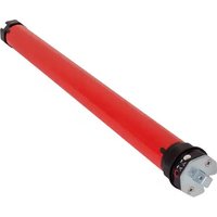
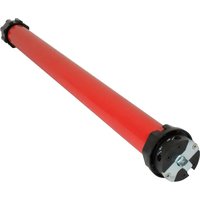
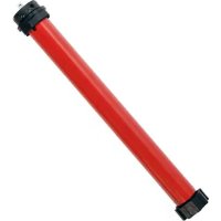
| Product type | Tubular motor for rolling shutters and blinds |
| Brand | Superrollo |
| Model | RM10MM |
| Torque | 10 Nm |
| Rotation speed | 15 rpm |
| Voltage / Frequency | 230 V / 50 Hz |
| Power consumption | 112 W |
| Rated current | 0.49 A |
| Protection rating | IP44 |
| Maximum operating time | 4 minutes |
| Cable length | 2.0 m |
| Total length | 500 mm |
| Compatible shaft type | SW60 |
| Max shutter area (plastic profile 4 kg/m²) | 4.2 m² |
| Max shutter area (aluminum/wood profile 7 kg/m²) | 2.8 m² |
| Max weight of rolling shutter | 22 kg |
| Included accessories | Adapter, drive piece, drive bracket, safety clip, adjustment tool |
| Warranty | 24 months |
| Main functions | Lifting and lowering of rolling shutters and blinds, limit switch adjustment, thermal protection with automatic stop |
| Maintenance and cleaning | Disconnect the device before cleaning; do not use water or corrosive products |
| Safety | Automatic stop in case of overheating or overload; suitable for use in wet rooms according to DIN VDE 0100 standards |
| Repairability | Repairs only by Superrollo after-sales service; spare parts available |
| General information | Electrical connection by qualified electrician; use in accordance with the manual |
Frequently Asked Questions - RM10MM Superrollo
User questions about RM10MM Superrollo
0 question about this device. Answer the ones you know or ask your own.
Ask a new question about this device
Download the instructions for your Electric motor in PDF format for free! Find your manual RM10MM - Superrollo and take your electronic device back in hand. On this page are published all the documents necessary for the use of your device. RM10MM by Superrollo.