Matic 251 - Welding machine Miller - Free user manual and instructions
Find the device manual for free Matic 251 Miller in PDF.
Frequently Asked Questions - Matic 251 Miller
User questions about Matic 251 Miller
0 question about this device. Answer the ones you know or ask your own.
Ask a new question about this device
Download the instructions for your Welding machine in PDF format for free! Find your manual Matic 251 - Miller and take your electronic device back in hand. On this page are published all the documents necessary for the use of your device. Matic 251 by Miller.
USER MANUAL Matic 251 Miller
Flux Cored (FCAW) Welding
Description


Arc Welding Power Source
and Wire Feeder
Millermatic 251
OWNER'S MANUAL
MANUAL DEL OPERADOR
Visit our website at
www.MillerWelds.com
File: MIG (GMAW)

From Miller to You
Thank you and congratulations on choosing Miller. Now you can get the job done and get it done right. We know you don't have time to do it any other way.
That's why when Niels Miller first started building arc welders in 1929, he made sure his products offered long-lasting value and superior quality. Like you, his customers couldn't afford anything less. Miller products had to be more than the best they could be. They had to be the best you could buy.
Today, the people that build and sell Miller products continue the tradition. They're just as committed to providing equipment and service that meets the high standards of quality and value established in 1929.
This Owner's Manual is designed to help you get the most out of your Miller products. Please take time to read the Safety precautions. They will help you protect yourself against potential hazards on the worksite.

Miller is the first welding equipment manufacturer in the U.S.A. to be registered to the ISO 9001:2000 Quality System Standard.
We've made installation and operation quick and easy. With Miller you can count on years of reliable service with proper maintenance. And if for some reason the unit needs repair, there's a Troubleshooting section that will help you figure out what the problem is. The parts list will then help you to decide the exact part you may need to fix the problem. Warranty and service information for your particular model are also provided.
Miller Electric manufactures a full line of welders and welding related equipment.
For information on other quality Miller
products, contact your local Miller distributor to receive the latest full line catalog or individual specification sheets. To locate your nearest distributor or service agency call 1-800-4-A-Miller, or visit us at www.MillerWelds.com on the web.

Working as hard as you do - every power source from Miller is backed by the most hassle-free warranty in the business.
TABLE OF CONTENTS
SECTION 1 - SAFETY PRECAUTIONS - READ BEFORE USING
1-1. Symbol Usage 1
1-2. Arc Welding Hazards 1
1-3. Additional Symbols For Installation, Operation, And Maintenance 3
1-4. California Proposition 65Warnings 3
1-5. Principal Safety Standards 4
1-6. EMF Information 4
SECTION 2 - CONSIGNES DE SECURITE - LIRE AVANT UTILISATION 5
SECTION 8 - MIG WELDING (GMAW) GUIDELINES 30
8-1. Typical MIG Process Connections 30
8-2. Typical MIG Process Control Settings 31
8-3.Holding And Positioning Welding Gun 32
8-4. Conditions That Affect Weld Bead Shape 33
8-5. Gun Movement During Welding 34
8-6. Poor Weld Bead Characteristics 34
8-7. Good Weld Bead Characteristics 34
8-8. Troubleshooting - Excessive Spatter 35
8-9. Troubleshooting - Porosity 35
8-10. Troubleshooting - Excessive Penetration 35
8-11. Troubleshooting - Lack Of Penetration 36
8-12. Troubleshooting - Incomplete Fusion 36
8-13.Troubleshooting-Burn-Through 36
8-14. Troubleshooting - Waviness Of Bead 37
8-15. Troubleshooting - Distortion 37
8-16. Common MIG Shielding Gases 38
8-17. Troubleshooting Guide For Semiautomatic Welding Equipment 38
SECTION 9 - PARTS LIST 40
WARRANTY
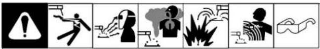
Warning: Protect yourself and others from injury — read and follow these precautions.
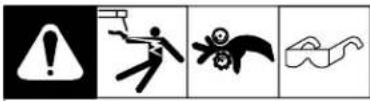
1-1. Symbol Usage

Means Warning! Watch Out! There are possible hazards with this procedure! The possible hazards are shown in the adjoining symbols.
Marks a special safety message.
Means "Note", not safety related.

This group of symbols means Warning! Watch Out! possible ELECTRIC SHOCK, MOVING PARTS, and HOT PARTS hazards. Consult symbols and related instructions below for necessary actions to avoid the hazards.
1-2. Arc Welding Hazards
The symbols shown below are used throughout this manual to call attention to and identify possible hazards. When you see the symbol, watch out, and follow the related instructions to avoid the hazard. The safety information given below is only a summary of the more complete safety information found in the Safety Standards listed in Section 1-5. Read and follow all Safety Standards.
Only qualified persons should install, operate, maintain, and repair this unit.
During operation, keep everybody, especially children, away.
ELECTRIC SHOCK can kill.
Touching live electrical parts can cause fatal shocks or severe burns. The electrode and work circuit is electrically live whenever the output is on. The input power circuit and machine internal circuits are also
live when power is on. In semiautomatic or automatic wire welding, the wire, wire reel, drive roll housing, and all metal parts touching the welding wire are electrically live. Incorrectly installed or improperly grounded equipment is a hazard.
- Do not touch live electrical parts.
Wear dry, hole-free insulating gloves and body protection.
Insulate yourself from work and ground using dry insulating mats or covers big enough to prevent any physical contact with the work or ground. - Do not use AC output in damp areas, if movement is confined, or if there is a danger of falling.
- Use AC output ONLY if required for the welding process.
-If AC output is required, use remote output control if present on unit.
Additional safety precautions are required when any of the following electrically hazardous conditions are present: in damp locations or while wearing wet clothing; on metal structures such as floors, gratings, or scaffolds; when in cramped positions such as sitting, kneeling, or lying; or when there is a high risk of unavoidable or accidental contact with the workpiece or ground. For these conditions, use the following equipment in order presented: 1) a semiautomatic DC constant voltage (wire) welder, 2) a DC manual (stick) welder, or 3) an AC welder with reduced open-circuit voltage. In most situations, use of a DC, constant voltage wire welder is recommended. And, do not work alone! - Disconnect input power or stop engine before installing or servicing this equipment. Lockout/tagout input power according to OSHA 29 CFR 1910.147 (see Safety Standards).
- Properly install and ground this equipment according to its Owner's Manual and national, state, and local codes.
- Always verify the supply ground - check and be sure that input power cord ground wire is properly connected to ground terminal in disconnect box or that cord plug is connected to a properly grounded receptacle outlet.
-
When making input connections, attach proper grounding conductor first - double-check connections.
Frequently inspect input power cord for damage or bare wiring replace cord immediately if damaged - bare wiring can kill. -
Turn off all equipment when not in use.
- Do not use worn, damaged, undersized, or poorly spliced cables.
Do not drape cables over your body.
If earth grounding of the workpiece is required, ground it directly with a separate cable. - Do not touch electrode if you are in contact with the work, ground, or another electrode from a different machine.
- Do not touch electrode holders connected to two welding machines at the same time since double open-circuit voltage will be present.
- Use only well-maintained equipment. Repair or replace damaged parts at once. Maintain unit according to manual.
Wear a safety harness if working above floor level. - Keep all panels and covers securely in place.
- Clamp work cable with good metal-to-metal contact to workpiece or worktable as near the weld as practical.
Insulate work clamp when not connected to workpiece to prevent contact with any metal object. - Do not connect more than one electrode or work cable to any single weld output terminal.
SIGNIFICANT DC VOLTAGE exists in inverter-type welding power sources after removal of input power.
- Turn Off inverter, disconnect input power, and discharge input capacitors according to instructions in Maintenance Section before touching any parts.
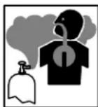
FUMES AND GASES can be hazardous.
Welding produces fumes and gases. Breathing these fumes and gases can be hazardous to your health.
- Keep your head out of the fumes. Do not breathe the fumes.
- If inside, ventilate the area and/or use local forced ventilation at the arc to remove welding fumes and gases.
If ventilation is poor, wear an approved air-supplied respirator. - Read and understand the Material Safety Data Sheets (MSDSs) and the manufacturer's instructions for metals, consumables, coatings, cleaners, and greasers.
Work in a confined space only if it is well ventilated, or while wearing an air-supplied respirator. Always have a trained watchperson nearby. Welding fumes and gases can displace air and lower the oxygen level causing injury or death. Be sure the breathing air is safe. - Do not weld in locations near degreasing, cleaning, or spraying operations. The heat and rays of the arc can react with vapors to form highly toxic and irritating gases.
- Do not weld on coated metals, such as galvanized, lead, or cadmium plated steel, unless the coating is removed from the weld area, the area is well ventilated, and while wearing an air-supplied respirator. The coatings and any metals containing these elements can give off toxic fumes if welded.
ARC RAYS can burn eyes and skin.
Arc rays from the welding process produce intense visible and invisible (ultraviolet and infrared) rays that can burn eyes and skin. Sparks fly off from the weld.
- Wear an approved welding helmet fitted with a proper shade of filter lenses to protect your face and eyes when welding or watching (see ANSI Z49.1 and Z87.1 listed in Safety Standards).
- Wear approved safety glasses with side shields under your helmet.
- Use protective screens or barriers to protect others from flash, glare and sparks; warn others not to watch the arc.
- Wear protective clothing made from durable, flame-resistant material (leather, heavy cotton, or wool) and foot protection.
WELDING can cause fire or explosion.
Welding on closed containers, such as tanks, drums, or pipes, can cause them to blow up. Sparks can fly off from the welding arc. The flying sparks, hot workpiece, and hot equipment can cause fires and
burns. Accidental contact of electrode to metal objects can cause sparks, explosion, overheating, or fire. Check and be sure the area is safe before doing any welding.
- Remove all flammables within 35 ft (10.7 m) of the welding arc. If this is not possible, tightly cover them with approved covers.
- Do not weld where flying sparks can strike flammable material.
- Protect yourself and others from flying sparks and hot metal.
- Be alert that welding sparks and hot materials from welding can easily go through small cracks and openings to adjacent areas.
Watch for fire, and keep a fire extinguisher nearby. - Be aware that welding on a ceiling, floor, bulkhead, or partition can cause fire on the hidden side.
- Do not weld on closed containers such as tanks, drums, or pipes, unless they are properly prepared according to AWS F4.1 (see Safety Standards).
- Connect work cable to the work as close to the welding area as practical to prevent welding current from traveling long, possibly unknown paths and causing electric shock, sparks, and fire hazards.
- Do not use welder to thaw frozen pipes.
- Remove stick electrode from holder or cut off welding wire at contact tip when not in use.
- Wear oil-free protective garments such as leather gloves, heavy shirt, cuffless trousers, high shoes, and a cap.
- Remove any combustibles, such as a butane lighter or matches, from your person before doing any welding.
- Follow requirements in OSHA 1910.252 (a) (2) (iv) and NFPA 51B for hot work and have a fire observer and extinguisher nearby.
FLYING METAL can injure eyes.
Welding, chipping, wire brushing, and grinding cause sparks and flying metal. As welds cool, they can throw off slag.
- Wear approved safety glasses with side shields even under your welding helmet.
BUILDUP OF GAS can injure or kill.
- Shut off shielding gas supply when not in use.
Always ventilate confined spaces or use approved air-supplied respirator.
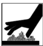
HOT PARTS can cause severe burns.
- Do not touch hot parts bare handed.
- Allow cooling period before working on gun or torch.
- To handle hot parts, use proper tools and/or wear heavy, insulated welding gloves and clothing to prevent burns.
MAGNETIC FIELDS can affect pacemakers.
Pacemaker wearers keep away.
Wearers should consult their doctor before going near arc welding, gouging, or spot welding operations.

NOISE can damage hearing.
Noise from some processes or equipment can damage hearing.
- Wear approved ear protection if noise level is high.
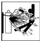
CYLINDERS can explode if damaged.
Shielding gas cylinders contain gas under high pressure. If damaged, a cylinder can explode. Since gas cylinders are normally part of the welding process, be sure to treat them carefully.
- Protect compressed gas cylinders from excessive heat, mechanical shocks, physical damage, slag, open flames, sparks, and arcs.
- Install cylinders in an upright position by securing to a stationary support or cylinder rack to prevent falling or tipping.
- Keep cylinders away from any welding or other electrical circuits.
- Never drape a welding torch over a gas cylinder.
- Never allow a welding electrode to touch any cylinder.
- Never weld on a pressurized cylinder - explosion will result.
- Use only correct shielding gas cylinders, regulators, hoses, and fittings designed for the specific application; maintain them and associated parts in good condition.
- Turn face away from valve outlet when opening cylinder valve.
- Keep protective cap in place over valve except when cylinder is in use or connected for use.
- Use the right equipment, correct procedures, and sufficient number of persons to lift and move cylinders.
- Read and follow instructions on compressed gas cylinders, associated equipment, and Compressed Gas Association (CGA) publication P-1 listed in Safety Standards.
1-3. Additional Symbols For Installation, Operation, And Maintenance
FIRE OR EXPLOSION hazard.
-Do not install or place unit on, over, or near combustible surfaces.
-Do not install unit near flammables.
- Do not overload building wiring - be sure power supply system is properly sized, rated, and protected to handle this unit.
FALLING UNIT can cause injury.
- Use lifting eye to lift unit only, NOT running gear, gas cylinders, or any other accessories.
- Use equipment of adequate capacity to lift and support unit.
- If using lift forks to move unit, be sure forks are long enough to extend beyond opposite side of unit.
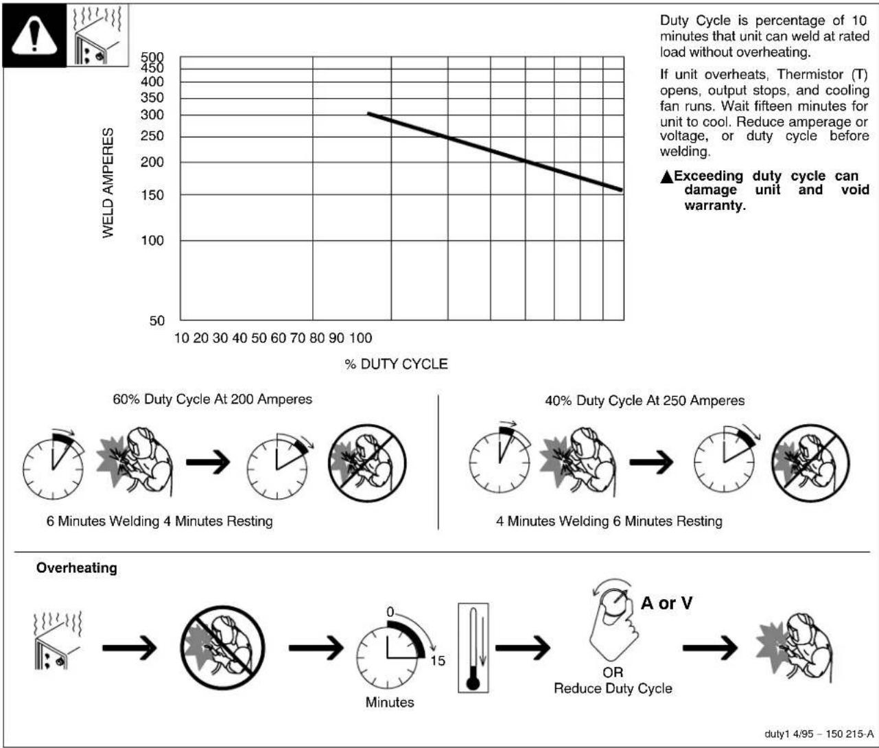
OVERUSE can cause OVERHEATING
-Allow cooling period; follow rated duty cycle.
- Reduce current or reduce duty cycle before starting to weld again.
- Do not block or filter airflow to unit.
STATIC (ESD) can damage PC boards.
- Put on grounded wrist strap BEFORE handling boards or parts.
- Use proper static-proof bags and boxes to store, move, or ship PC boards.

MOVING PARTS can cause injury.
- Keep away from moving parts.
- Keep away from pinch points such as drive rolls.
WELDING WIRE can cause injury.
- Do not press gun trigger until instructed to do so.
- Do not point gun toward any part of the body, other people, or any metal when threading welding wire.
1-4. California Proposition 65Warnings
Welding or cutting equipment produces fumes or gases which contain chemicals known to the State of California to cause birth defects and, in some cases, cancer. (California Health & Safety Code Section 25249.5 et seq.)
Battery posts, terminals and related accessories contain lead and lead compounds, chemicals known to the State of California to cause cancer and birth defects or other reproductive harm. Wash hands after handling.

MOVING PARTS can cause injury.
- Keep away from moving parts such as fans.
- Keep all doors, panels, covers, and guards closed and securely in place.
- Have only qualified persons remove doors, panels, covers, or guards for maintenance as necessary.
- Reinstall doors, panels, covers, or guards when maintenance is finished and before reconnecting input power.
READ INSTRUCTIONS.
-Read Owner's Manual before using or servicing unit.
- Use only genuine Miller/Hobart replacement parts.
H.F. RADIATION can cause interference.
- High-frequency (H.F.) can interfere with radio navigation, safety services, computers, and communications equipment.
- Have only qualified persons familiar with electronic equipment perform this installation.
The user is responsible for having a qualified electrician promptly correct any interference problem resulting from the installation.
If notified by the FCC about interference, stop using the equipment at once.
- Have the installation regularly checked and maintained.
- Keep high-frequency source doors and panels tightly shut, keep spark gaps at correct setting, and use grounding and shielding to minimize the possibility of interference.
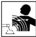
ARC WELDING can cause interference.
Electromagnetic energy can interfere with sensitive electronic equipment such as computers and computer-driven equipment such as robots.
- Be sure all equipment in the welding area is electromagnetically compatible.
To reduce possible interference, keep weld cables as short as possible, close together, and down low, such as on the floor.
-Locate welding operation 100 meters from any sensitive electronic equipment.
- Be sure this welding machine is installed and grounded according to this manual.
- If interference still occurs, the user must take extra measures such as moving the welding machine, using shielded cables, using line filters, or shielding the work area.
For Gasoline Engines:
Engine exhaust contains chemicals known to the State of California to cause cancer, birth defects, or other reproductive harm.
For Diesel Engines:
Diesel engine exhaust and some of its constituents are known to the State of California to cause cancer, birth defects, and other reproductive harm.
1-5. Principal Safety Standards
Safety in Welding, Cutting, and Allied Processes, ANSI Standard Z49.1, from Global Engineering Documents (phone: 1-877-413-5184, website: www.global.ihs.com).
Recommended Safe Practices for the Preparation for Welding and Cutting of Containers and Piping, American Welding Society Standard AWS F4.1 from Global Engineering Documents (phone: 1-877-413-5184, website: www.global.ihs.com).
National Electrical Code, NFPA Standard 70, from National Fire Protection Association, P.O. Box 9101, 1 Battery March Park, Quincy, MA 02269-9101 (phone: 617-770-3000, website: www.nfpa.org).
Safe Handling of Compressed Gases in Cylinders, CGA Pamphlet P-1, from Compressed Gas Association, 1735 Jefferson Davis Highway, Suite 1004, Arlington, VA 22202-4102 (phone: 703-412-0900, website: www.cghanet.com).
Code for Safety in Welding and Cutting, CSA Standard W117.2, from Canadian Standards Association, Standards Sales, 178 Rexdale
Boulevard, Rexdale, Ontario, Canada M9W 1R3 (phone: 800-463-6727 or in Toronto 416-747-4044, website: www.csa-international.org).
Practice For Occupational And Educational Eye And Face Protection, ANSI Standard Z87.1, from American National Standards Institute, 11 West 42nd Street, New York, NY 10036-8002 (phone: 212-642-4900, website: www.ansi.org).
Standard for Fire Prevention During Welding, Cutting, and Other Hot Work, NFPA Standard 51B, from National Fire Protection Association, P.O. Box 9101, 1 Battery March Park, Quincy, MA 02269-9101 (phone: 617-770-3000, website: www.nfpa.org).
OSHA, Occupational Safety and Health Standards for General Industry, Title 29, Code of Federal Regulations (CFR), Part 1910, Subpart Q, and Part 1926, Subpart J, from U.S. Government Printing Office, Superintendent of Documents, P.O. Box 371954, Pittsburgh, PA 15250 (there are 10 Regional Offices--phone for Region 5, Chicago, is 312-353-2220, website: www.osha.gov).
1-6. EMF Information
Considerations About Welding And The Effects Of Low Frequency Electric And Magnetic Fields
Welding current, as it flows through welding cables, will cause electromagnetic fields. There has been and still is some concern about such fields. However, after examining more than 500 studies spanning 17 years of research, a special blue ribbon committee of the National Research Council concluded that: "The body of evidence, in the committee's judgment, has not demonstrated that exposure to power-frequency electric and magnetic fields is a human-health hazard." However, studies are still going forth and evidence continues to be examined. Until the final conclusions of the research are reached, you may wish to minimize your exposure to electromagnetic fields when welding or cutting.
To reduce magnetic fields in the workplace, use the following procedures:
- Keep cables close together by twisting or taping them.
- Arrange cables to one side and away from the operator.
- Do not coil or drape cables around your body.
- Keep welding power source and cables as far away from operator as practical.
- Connect work clamp to workpiece as close to the weld as possible.
About Pacemakers:
Pacemaker wearers consult your doctor before welding or going near welding operations. If cleared by your doctor, then following the above procedures is recommended.
Recommended Safe Practices for the Preparation for Welding and Cutting of Containers and Piping, American Welding Society Standard AWS F4.1 de Global Engineering Documents (telephone: 1-877-413-5184, site Internet: www.global.ihs.com).
National Electrical Code, NFPA Standard 70, de National Fire Protection Association, P.O. Box 9101, 1 Battery March Park, Quincy, MA 02269-9101 (telephone: 617-770-3000, site Internet: www.nfpa.org).
Safe Handling of Compressed Gases in Cylinders, CGA Pamphlet P-1, de Compressed Gas Association, 1735 Jefferson Davis Highway, Suite 1004, Arlington, VA 22202-4102 (telephone: 703-412-0900, site Internet: www.cganet.com).
Code for Safety in Welding and Cutting, CSA Standard W117.2, de Canadian Standards Association, Standards Sales, 178 Rexdale
Boulevard, Rexdale, Ontario, Canada M9W 1R3 (telephone : 800-463-6727 ou à Toronto 416-747-4044, site Internet : www.csa-international.org).
Practice For Occupational And Educational Eye And Face Protection, ANSI Standard Z87.1, de American National Standards Institute, 11 West 42nd Street, New York, NY 10036-8002 (telephone: 212-642-4900, site Internet: www.ansi.org).
Standard for Fire Prevention During Welding, Cutting, and Other Hot Work, NFPA Standard 51B, de National Fire Protection Association, P.O. Box 9101, 1 Battery March Park, Quincy, MA 02269-9101 (telephone: 617-770-3000, site Internet: www.nfpa.org).
OSHA, Occupational Safety and Health Standards for General Industry, Title 29, Code of Federal Regulations (CFR), Part 1910, Subpart Q, and Part 1926, Subpart J, de U.S. Government Printing Office, Superintendent of Documents, P.O. Box 371954, Pittsburgh, PA 15250 (il y a 10 bureaux régionaux--le téléphone de la région 5, Chicago, est 312-353-2220, site Internet: www.osha.gov).
2-6. Information EMF
| o|o Wire Feed Output | ○→ | X Duty Cycle | ○/ Do Not Switch While Welding |
| V Volts Increase | On Off | I | ○ |
| Gas Metal Arc Welding (GMAW) Gun | Wire Feed Spool Gun | ←O Gas Input Gas Output | Output |
| Voltage Input Press Torque | Tort | U0 Rated No-Load Voltage (Average) |
SECTION 4 - INSTALLATION
4-1. Specifications
| Rated Output | Max. Open-Circuit Voltage | Amps Input at Rated Output (60% Duty Cycle), 50 or 60 Hz, Single-Phase | |||||||
| 200 (208) V 230 V 400 V 460 V 575 V KVA KW | |||||||||
| 250 A at 28 VDC,40% Duty Cycle | 200 A at 28 VDC,60% Duty Cycle | 38 48 | 2.3* | 422* | 241.2* | 211* | 170.8* | 9.80.46* | 7.50.13* |
| Wire Type and Diameter | Wire Feed Speed | Dimensions | Net Weight | ||
| Solid Steel | Stainless Steel | Flux Cored | 25-700 IPM (.65-17.8 m/min) | H: 32 in (813 mm) W: 19 in (483 mm) D: 39 in (991 mm) | 215 lb (98 kg) |
| .023 - .045 in (0.6 - 1.2 mm) | .023 - .045 in (0.6 - 1.2 mm) | .030 - .045 in (0.8 - 1.2 mm) | |||
| * While idling | |||||
| Operating Temperature Range - -20C to +40C | Storage Temperature Range - -30C to + 50C | ||||
4-2. Welding Power Source Duty Cycle And Overheating
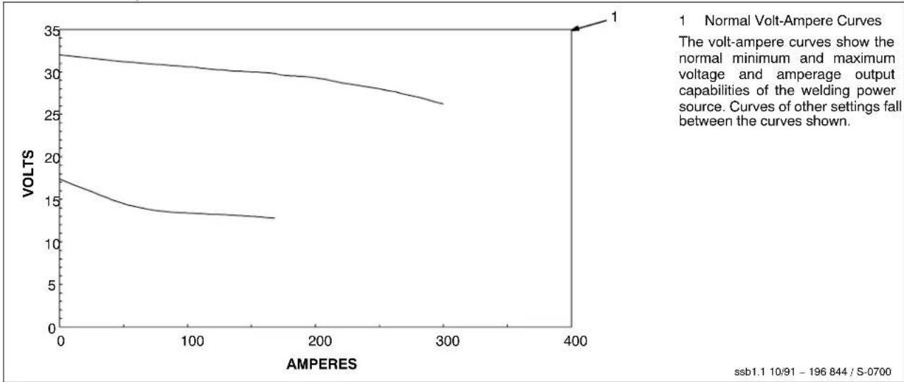
4-3. Volt-Ampere Curves
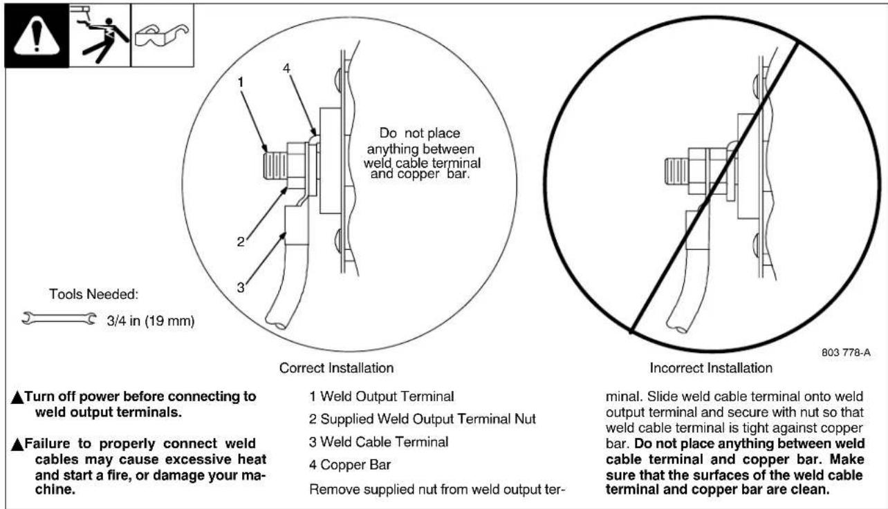
4-4. Connecting To Weld Output Terminals
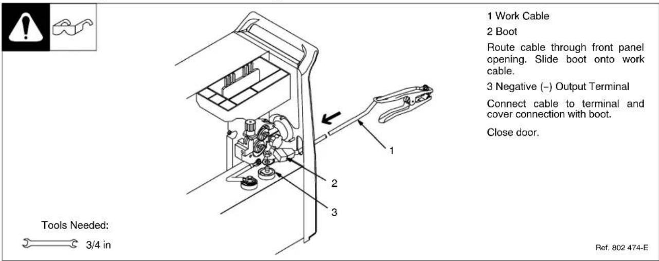
4-5. Installing Work Cable And Clamp
4-6. Connecting Spoolmatic® 15A Or 30A Gun
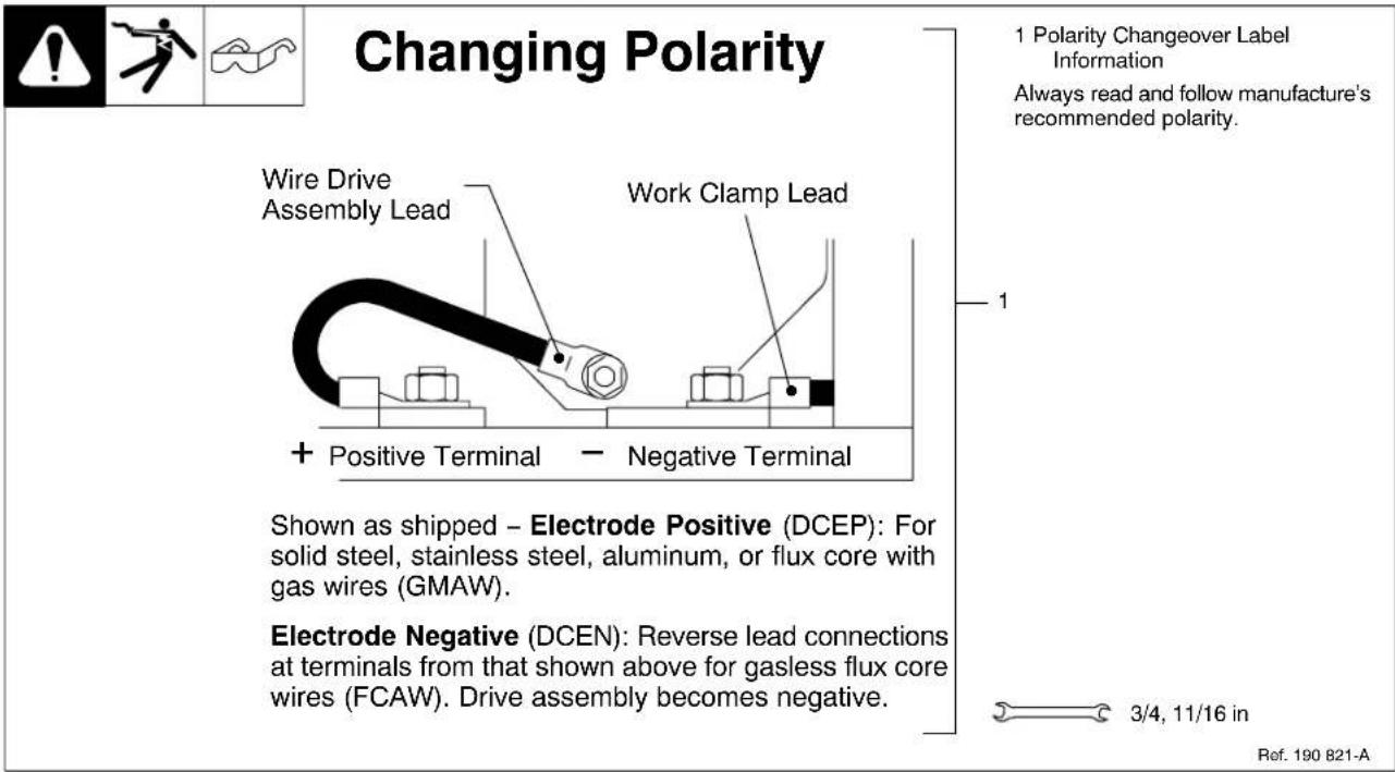
4-7. Setting Gun Polarity For Wire Type
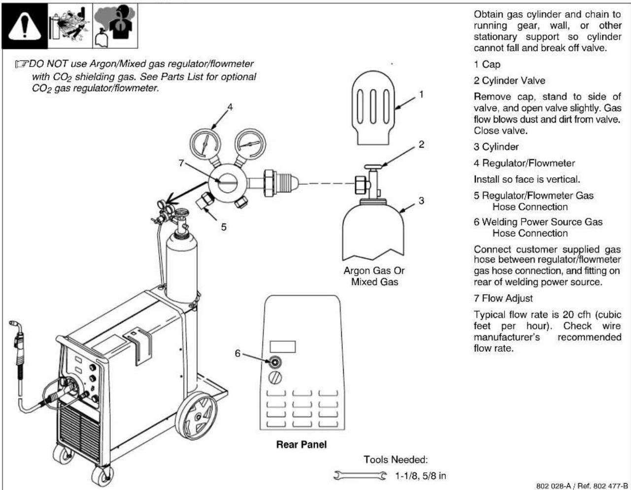
4-8. Installing Gas Supply
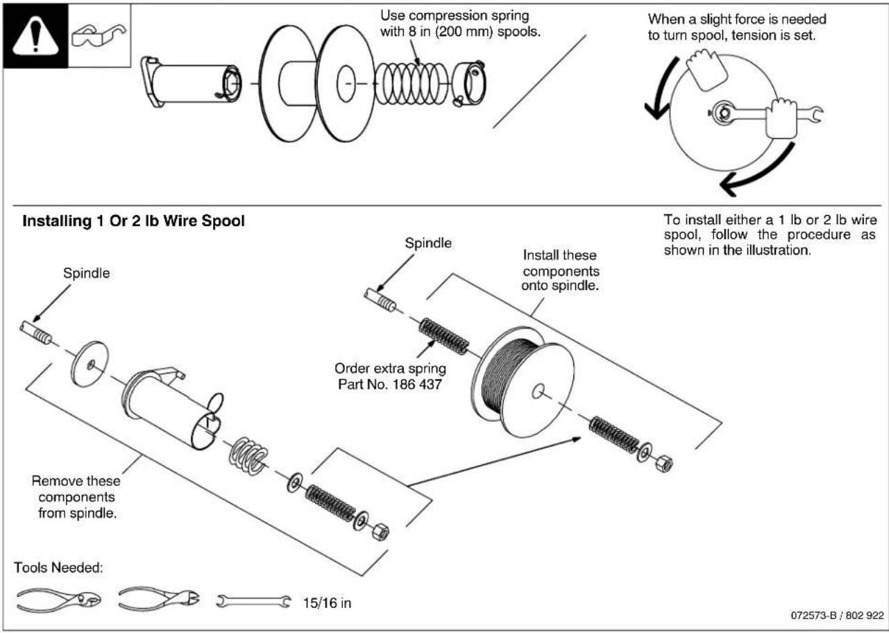
4-9. Installing Wire Spool And Adjusting Hub Tension
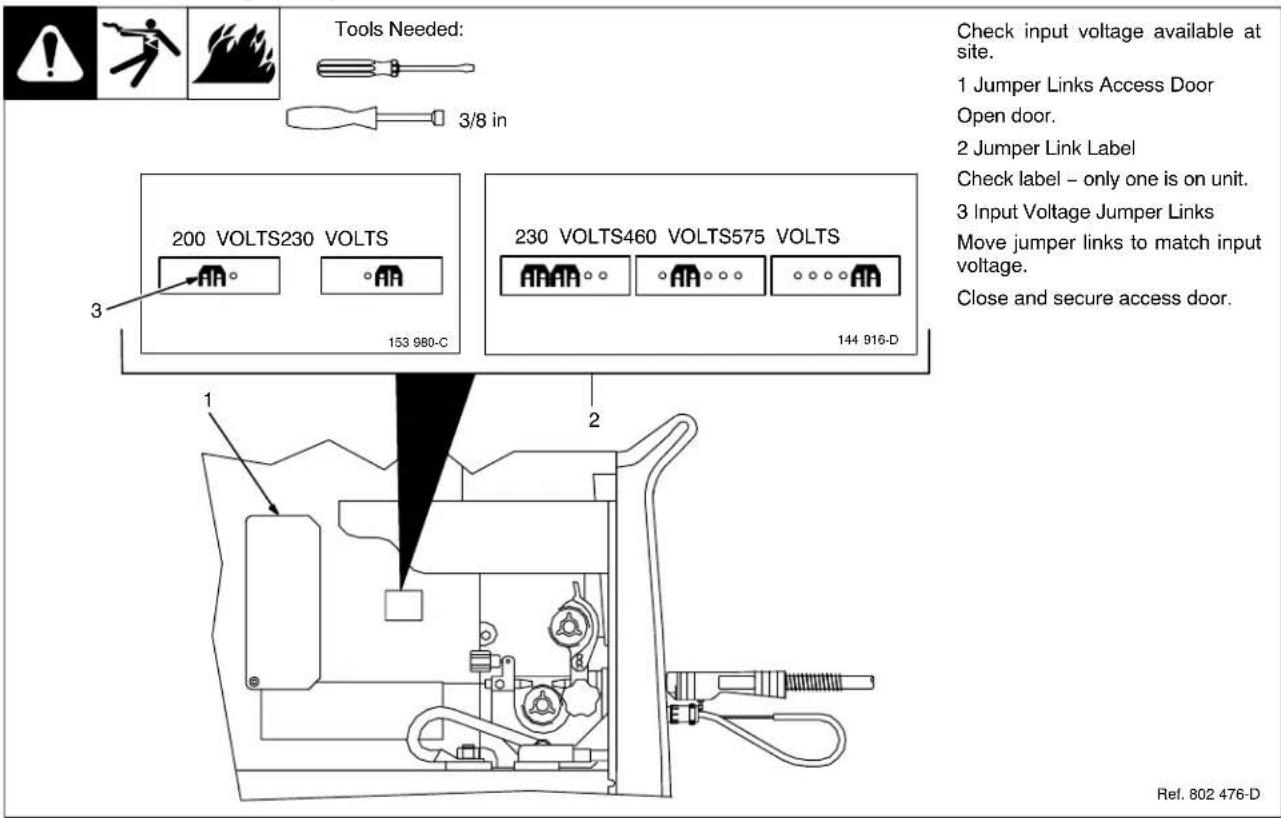
4-10. Positioning Jumper Links
4-11. Electrical Service Guide
| Input Voltage 200 230 400 460 575 | |||||
| Input Amperes At Rated Output 48 42 24 21 17 | |||||
| Max Recommended Standard Fuse Or Circuit Breaker Rating In Amperes Circuit Breaker 1, Time-Delay 2 Normal Operating 3 | 60 50 | 30 25 20 | |||
| 70 60 | 35 30 25 | ||||
| Min Input Conductor Size In AWG4 | 8 8 12 | 12 14 | |||
| Max Recommended Input Conductor Length In Feet (Meters) | 96 (29) | 127 (39) | 156 (47) | 206 (63) | 209 (64) |
| Min Grounding Conductor Size In AWG4 | 8 10 1 | 12 14 |
Reference: 2005 National Electrical Code (NEC) (including article 630)
1 Choose a circuit breaker with time-current curves comparable to a Time Delay Fuse.
2 "Time-Delay" fuses are UL class "RK5"
3 "Normal Operating" (general purpose - no intentional delay) fuses are UL class "K5" (up to and including 60 amp), and UL class "H" (65 amp and above).
4 Conductor data in this section specifies conductor size (excluding flexible cord or cable) between the panelboard and the equipment per NEC Table 310.16. If a flexible cord or cable is used, minimum conductor size may increase. See NEC Table 400.5(A) for flexible cord and cable requirements.
Caution: Failure to follow these fuse and circuit breaker recommendations could create an electric shock or fire hazard. These recommendations are for a dedicated branch circuit that applies to the rated output and duty cycle of the welding power source.
4-12. Selecting A Location And Connecting Input Power
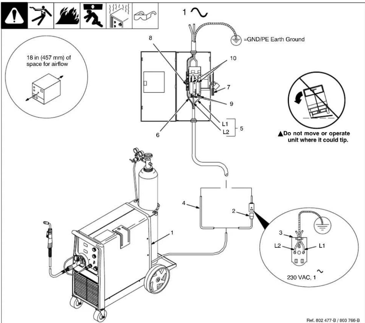
Installation must meet all National and Local Codes - have only qualified persons make this installation.
Disconnect and lockout/tagout input power before connecting input conductors from unit.
Always connect green or green/yellow conductor to supply grounding terminal first, and never to a line terminal.
Special installation may be required where gasoline or volatile liquids are present - see NEC Article 511 or CEC Section 20.
1 Rating Label
Supply correct input power.
2 Plug (NEMA Type 6-50P)
3 Receptacle [NEMA Type 6-50R (Customer Supplied)]
4 Input Power Cord.
Connect directly to line disconnect device if hard wiring is required.
5 Black And White Input Conductor (L1 And L2)
6 Green Or Green/Yellow Grounding Conductor
7 Disconnect Device (switch shown in the OFF position)
8 Disconnect Device Grounding Terminal
9 Disconnect Device Line Terminals
Connect green or green/yellow grounding conductor to disconnect device grounding terminal first.
Connect input conductors L1 and L2 to disconnect device line terminals.
10 Over-Current Protection
Select type and size of over-current protection using Section 4-11 (fused disconnect switch shown).
Connect plug to receptacle if hard wiring method is not used.
Close and secure door on disconnect device. Remove lockout/tagout device, and place switch in the On position.
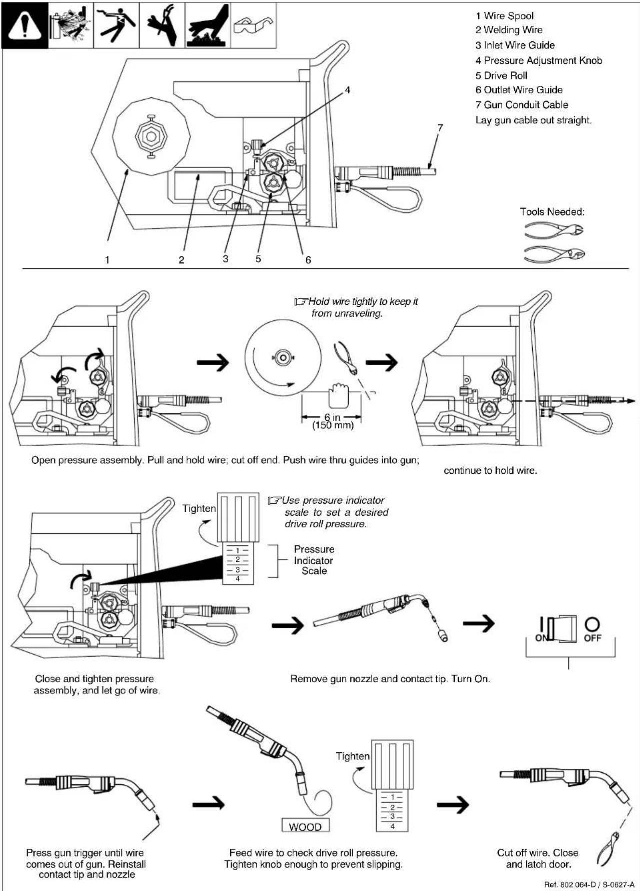
4-13. Threading Welding Wire
4-14. Using Gun/Cable Holder
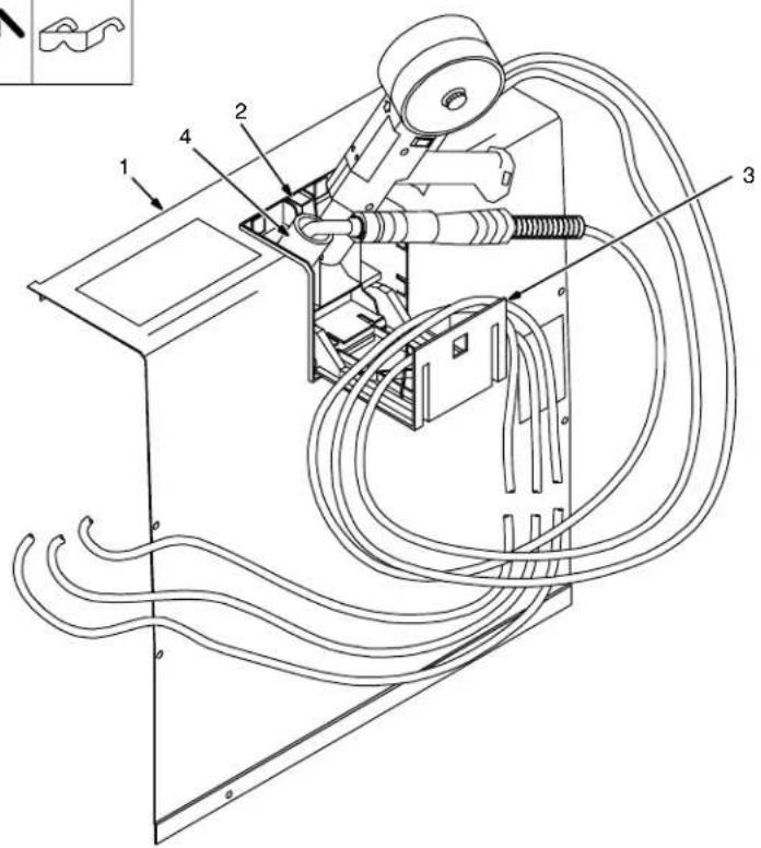
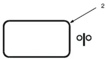
1 Side Panel
2 Latch
3 Cable Holder
Press latch down to release and open door.
4 Holster (2)
Wrap cable around cable holder, and place gun nozzle into holster.
Ref. 802 726-A
Notes
4-15. Weld Parameters
Selecting Wire, Gas and Control Settings
| What Material are You Welding? | Suggested Wire Types | Suggested Shielding Gases and Flow Rate | Wire Sizes (Diameter) |
| Steel | Solid (or hard) ER70S-6 | 100% CO2, 25 cfh | 0.023" (0.6mm) |
| 0.030" (0.8mm) | |||
| 0.035" (0.9mm) | |||
| 0.045" (1.1mm) | |||
| 75% Ar/25% CO2, 25 cfh (Ar/CO2 produces less spatter-better overall appearance) | 0.023" (0.6mm) | ||
| 0.030" (0.8mm) | |||
| 0.035" (0.9mm) | |||
| 0.045" (1.1mm) | |||
| Steel - for outdoor, windy applications or when weld appearance is not critical. | Flux core E71T-11 | No shielding gas required | 0.035" (0.9mm) |
| 0.045" (1.1mm) | |||
| Flux core E71T-1 | 100% CO2, 25 cfh | 0.035" (0.9mm) | |
| 75% Ar/25% CO2, 25 cfh | 0.045" (1.1mm) | ||
| Stainless steel | Stainless steel ER 308, ER 308L ER 308LSi | Tri-Mix, 35 cfh (90% He/7.5% Ar/2.5% CO2) | 0.023" (0.6mm) |
| 0.030" (0.8mm) | |||
| 0.035" (0.9mm) | |||
| 0.045" (1.1mm) | |||
| Aluminum with Optional Spoolmatic®15A or 30A spoolgun. | Aluminum 4043 ER | 100% Ar, 35 cfh | 0.030" (0.8mm) |
| 0.035" (0.9mm) | |||
| 0.047" (1.2mm) |
| 1/2" (12.7 mm) | 3/8" (9.5 mm) | 1/4" (6.4 mm) | 3/16" (4.8 mm) | 1/8" (3.2 mm) | 14 ga. (2.0 mm) | 16 ga. (1.6 mm) | 18 ga. (1.2 mm) | 20 ga. (0.9 mm) | 22 ga. (0.8 mm) |
| - | - | - | - | 20.0/320 | 19.0/280 | 18.5/220 | 18.0/190 | 17.6/170 | 17.0/140 |
| - | 22.5/420 | 21.5/380 | 20.5/325 | 19.5/295 | 19.0/230 | 18.5/185 | 18.0/135 | 17.5/120 | 17.0/105 |
| - | 23.0/325 | 21.5/290 | 20.5/245 | 20.0/220 | 19.0/175 | 18.5/160 | 18.0/125 | 17.5/100 | 17.0/85 |
| - | - | - | 19.5/510 | 18.0/385 | 17.0/300 | 16.5/240 | 15.5/180 | 15.3/140 | 15.0/130 |
| - | 22.0/530 | 19.6/435 | 18.5/375 | 17.0/305 | 16.5/235 | 16.0/210 | 15.5/170 | 15.0/130 | 14.5/110 |
| 23.5/475 | 21.5/425 | 19.0/320 | 18.0/280 | 17.0/245 | 16.5/200 | 16.0/165 | 15.5/135 | 15.0/110 | 14.5/95 |
| 24.5/335 | 21.5/300 | 19.0/260 | 18.0/230 | 17.0/200 | 16.5/165 | 16.0/155 | 15.5/110 | - | - |
| - | 16.5/250 | 15.5/225 | 15.0/210 | 14.5/180 | 14.2/120 | 14.0/105 | - | - | - |
| - | 17.5/170 | 16.5/130 | 15.5/110 | 15.0/90 | 14.5/70 | - | - | - | - |
| - | 24.0/385 | 23.0/360 | 21.5/310 | 20.5/275 | 20.0/250 | - | - | - | - |
| 25.5/380 | 24.5/340 | 23.0/305 | 21.5/265 | 20.5/240 | 20.0/210 | - | - | - | - |
| - | - | - | - | 21.0/500 | 19.5/360 | 18.5/270 | 18.0/250 | - | - |
| - | - | 22.5/500 | 21.5/480 | 21.0/420 | 19.5/360 | 18.5/250 | 17.5/220 | - | - |
| - | 24.5/485 | 22.5/440 | 21.5/400 | 20.0/350 | 19.0/275 | 18.5/225 | - | - | - |
| - | 24.0/330 | 22.5/310 | 21.5/285 | 20.5/275 | - | - | - | - | - |
| - | - | 23.0/570 | 21.0/500 | 19.0/450 | 18.5/425 | - | - | - | - |
| - | 25.0/615 | 23.0/520 | 21.5/450 | 19.0/400 | 18.5/375 | - | - | - | - |
| - | 24.5/445 | 22.5/375 | 21.0/305 | 19.0/265 | - | - | - | - | - |
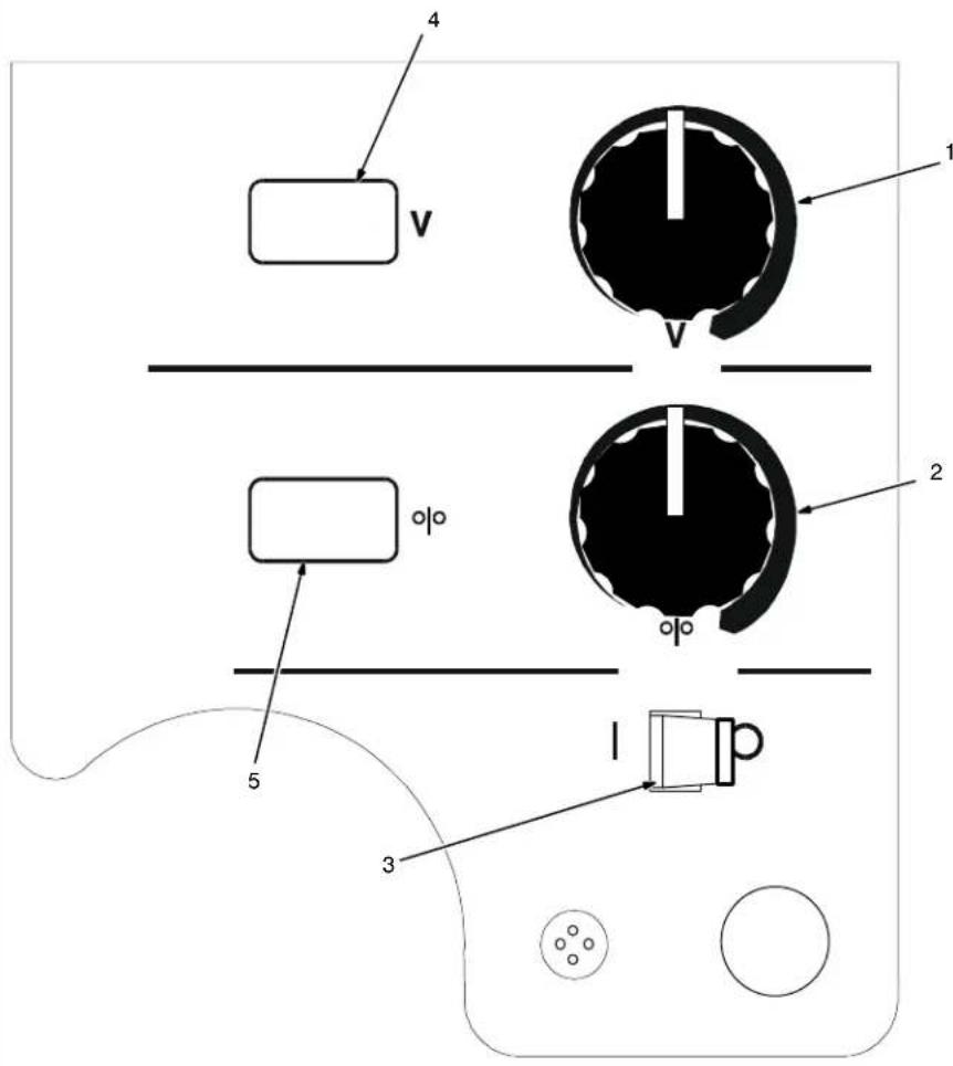
5-1. Controls
This unit has three automatic timers included in its operation to help save contact tips, gas, and wire:
Tip Saver - Weld output shuts off if tip is shorted to work surface.
Safety shut-off - Weld output will shut off if no arc is detected within 3 seconds after gun trigger is depressed.
Jog mode - When loading a new roll of wire or if the gun trigger is accidentally pressed, gas will shut off after 1 minute and wire will shut off after 2 minutes saving wire and gas.
1 Voltage Control
Turn control clockwise to increase voltage.
2 Wire Speed Control
Turn control clockwise to increase wire feed speed.
JOG Mode
If the trigger on either gun is held for more than 3 seconds without striking an arc, the unit will automatically shut off weld power (and shielding gas output on MIG gun only), but will feed wire continuously at the preset wire feed speed (which may be faster or slower than Run-in Speed) until trigger is released.
Run-in Wire Feed Speed Settings
Run-in settings for the MIG and Spool Guns are independently set and stored in unit memory. The settings are in percent of the welding wire feed speed preset. Both settings are adjustable from 25 to 150 percent.
MIG Gun Run-in is factory set at 100% which is recommended for most wire sizes and types.
Spool Gun Run-in is factory set at 50% which is recommended for .030 & .035 wire. A Run-in setting of 25% is recommended for .047 wire.
To check Run-in settings, start with the power switch OFF. Press and hold the MIG or Spool Gun Trigger while turning the power switch ON. The unit will power up with both the displays reading 888, then the voltage display will read --- and the wire feed display will read the preset Run-in percentage from memory for the gun selected. To return to the weld mode without making a change, simply release trigger and pull the trigger again momentarily (one second).
To change Run-in settings, start with the power switch OFF. Press and hold the MIG or Spool Gun Trigger while turning the power switch ON. The unit will power up with both the displays reading 888, then the voltage display will read --- and the wire feed display will read the preset Run-in percentage from memory for the gun selected. To change the Run-in value, release the trigger and turn the wire feed control knob (or the wire feed adjustment knob located on the bottom handle of the spool gun) to the desired setting for the selected gun. To return to weld mode after the Run-in speed change, pull the trigger momentarily (one second).
3 Power Switch
4 Voltmeter
5 Wire Feed Speed Meter
Ref. 205 637
5-2. Voltmeter And Wire Feed Speed Meter Operation
Both meters display 888 at unit power up. After one second, preset values appear on both meters. The MIG gun settings (not spool gun) are always the default at initial power up of the unit. If the power is reset to quickly, characters other than 888 may appear. To reset, turn power off for at least 3 seconds, then turn power back on.
Welding Status
When either a MIG gun or spool gun trigger is pressed and a welding arc is established, the voltmeter displays actual weld voltage. When the gun trigger is released and welding arc extinguished, the voltmeter displays the last actual voltage for 5 seconds and then returns to preset voltage.
If welding resumes before unit displays preset voltage, actual welding voltage will appear on the voltmeter.
The wire feed speed meter always displays preset wire feed speed (IPM).
Gun Selection
The wire feed speed meter will display preset wire feed speed (IPM) for the appropriate gun selection either MIG or spool gun. To preset desired wire feed speed, connect desired gun, press gun trigger for one second, and release trigger. The meter preset will be retained by the meter board until a different gun is connected and preset is performed or the unit is turned off and back on. The MIG gun settings (not spool gun) are always the default at initial power up of the unit.
Error Messages
Volt Meter Display (HL.P)
Wire Feed Speed Display (001)
HL.P 001 - Communication Lost between Control Board PC1 and Display Board PC2
HL.P 002 - Unit over temperature, unit is inoperative until temperature is reduced inside unit (see Section 6-2)
HL.P 003-No Open Circuit Voltage (OCV) detected when either trigger is pulled
HL.P 004 - Gun trigger was engaged for approximately 2 minutes with no arc detected, or weld wire is stuck causing a direct short. If HLP 004 occurs during power up, see Section 6-6.
HL.P 005 - Wire feed malfunction. Check wire feed delivery system (see Section 6-6).
See Section 6-6 for additional information on all HL.P codes.
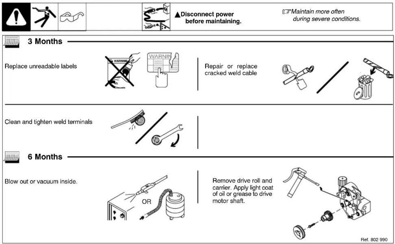
6-1. Routine Maintenance
6-2. Unit Overload
Thermistor T in SCR1 protects the unit from damage due to overheating. If HLP 002 is displayed on the meters, wait for unit to cool allowing fan motor to run before trying to weld. If unit is cool and no weld output continues, contact Factory Authorized Service Agent.
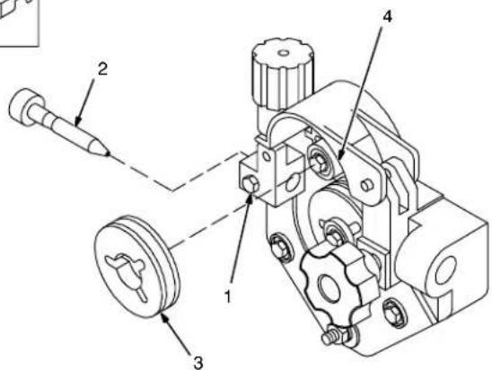
6-3. Changing Drive Roll and Wire Inlet Guide
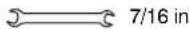
Tools Needed:
Ref. 802 990-A
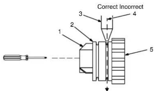
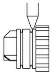
6-4. Aligning Drive Rolls and Wire Guide
Tools Needed:

1 Securing Screw
2 Inlet Wire Guide
Loosen screw. Slide tip as close to drive rolls as possible without touching. Tighten screw.
3 Drive Roll
The drive roll consists of two different sized grooves. The stamped markings on the end surface of the drive roll refers to the groove on the opposite side of the drive roll. The groove closest to the motor shaft is the proper groove to thread (see Section 4-13).
4 Drive Roll Securing Nut
Turn nut one click to secure drive roll.
Turn Off power.
View is from top of drive rolls looking down with pressure assembly open.
1 Drive Roll Securing Nut
2 Drive Roll
3 Wire Guide
4 Welding Wire
5 Drive Gear
Insert screwdriver, and turn screw in or out until drive roll groove lines up with wire guide.
Close pressure roll assembly.
Ref. 800 412-A
6-5. Removing Knob From Front Panel
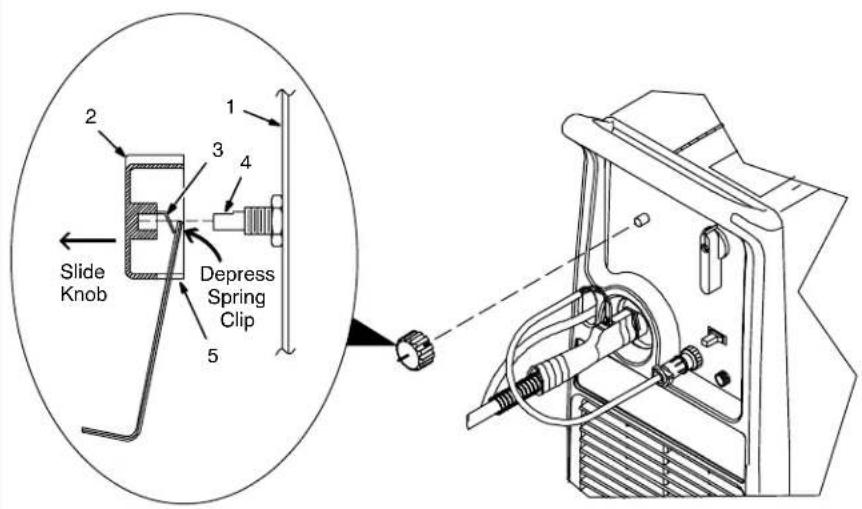
Turn Off power.
1 Front Panel
2 Knob
3 Spring Clip
4 Control Shaft
5 Slot
Rotate knob to allow access to slot. Insert Allen wrench (or stiff piece of wire) into slot, and while depressing spring clip, slide knob off control shaft.
To reinstall, push knob fully onto control shaft.
Ref. 803 346/ Ref. 803 863-B
6-6. Troubleshooting
| Trouble Remedy | ||
| No weld output; wire does not feed. | Be sure line disconnect switch is On (see Section 4-12). | |
| Replace building line fuse or reset circuit breaker if open (see Section 4-12). | ||
| Secure gun trigger connections (see welding gun Owner's Manual). | ||
| HL.P 001 appears on meters. Turn power switch off and back on, if HLP 001 appears on meters again, have Factory Authorized Service Agent check unit. | ||
| HL.P 002 appears on meters. Thermistor T is detecting an overheating condition. Wait for unit to cool allowing the fan to run. After unit is cool, if HLP 002 message remains, have Factory Authorized Service Agent check for an open Thermistor T (see Section 6-2). | ||
| HL.P 004 appears on meters. Reset message by releasing the trigger or removing stuck wire causing short circuit (see Section 5-2). If message remains, have Factory Authorized Service Agent check for shorted trigger leads. | ||
| Have Factory Authorized Service Agent check Power switch. | ||
| Have Factory Authorized Service Agent check all board connections and main control board. | ||
| No Weld Output; wire feeds. Connect work clamp to get good metal to metal contact. | ||
| Replace contact tip (see welding gun Owner's Manual. | ||
| HL.P 003 appears on meters, have Factory Authorized Service Agent check main control board and main rectifier. | ||
| Low weld output. | Connect unit to proper input voltage or check for low line voltage (see Section 4-12). | |
| Check input voltage jumper links and correct position if necessary (see Section 4-10). | ||
| Have Factory Authorized Service Agent check main control board. | ||
| Fan motor does not run. Have Factory Authorized Service Agent check fan-on-demand circuit. | ||
| Low, high, or erratic wire speed. Readjust front panel settings (see Section 5-1). | ||
| Change to correct size drive rolls (see Section 6-3). | ||
| Readjust drive roll pressure (see Section 4-13). | ||
| Replace inlet guide, contact tip, and/or liner if necessary (see welding gun Owner's Manual). | ||
| Check position of input jumper links (see Section 4-10). | ||
| Have Factory Authorized Service Agent check main control board. | ||
| No wire feed. Turn Wire Speed control to | higher setting (see Section 5-1). | |
| Clear obstruction in gun contact tip or liner (see welding gun Owner's Manual). | ||
| Readjust drive roll pressure (see Section 4-13). | ||
| Change to correct size drive rolls (see Section 6-3). | ||
| Rethread welding wire (see Section 4-13). | ||
| HL.P 002 appears on meters. Thermistor T is detecting an overheating condition. Wait for unit to cool allowing the fan to run. After unit is cool, If HLP 002 message remains, contact Factory Authorized Service Agent (see Section 6-2). | ||
| HL.P 004 appears on meters. Reset message by releasing the trigger or removing stuck wire causing short circuit (see Section 5-2) . If message remains, have Factory Authorized Service Agent check for shorted trigger leads. | ||
| HL.P 005 appears on meters. Wire feed malfunction. Check wire feed delivery system. | ||
| Check gun trigger and leads. Repair or replace gun if necessary. | ||
| Have Factory Authorized Service Agent check main control board. | ||
| WARNING | Do not touch live electrical parts. Disconnect input power or stop engine before servicing. Do not operate with covers removed. Have only qualified persons install, use, or service this unit. |
| ELECTRIC SHOCK HAZARD |
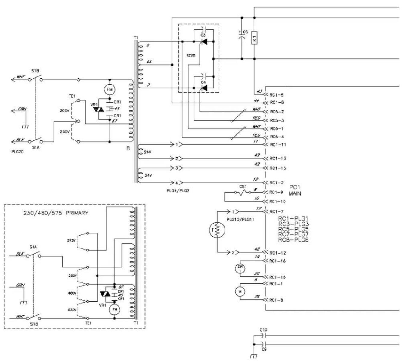
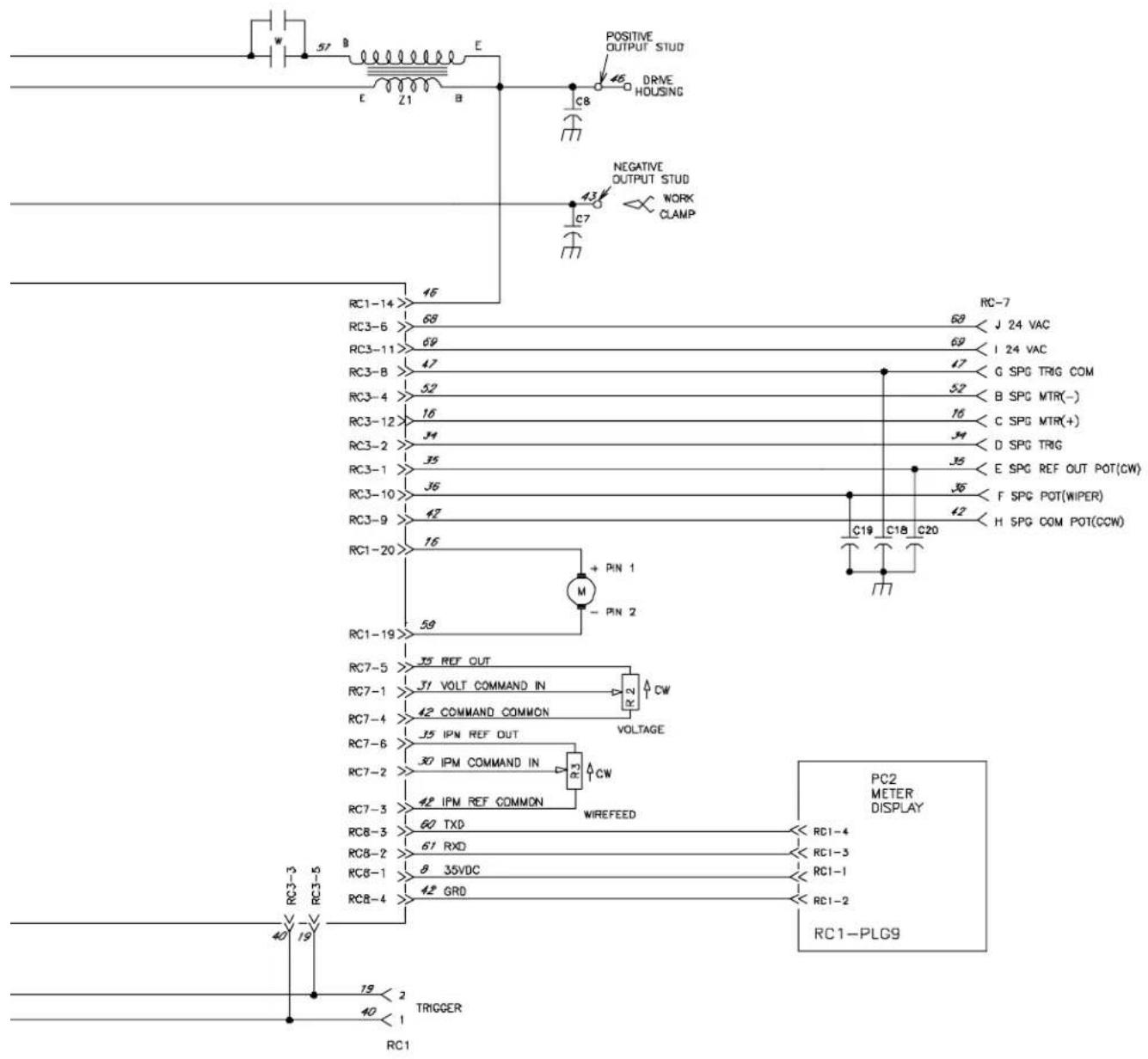
Figure 7-1. Circuit Diagram


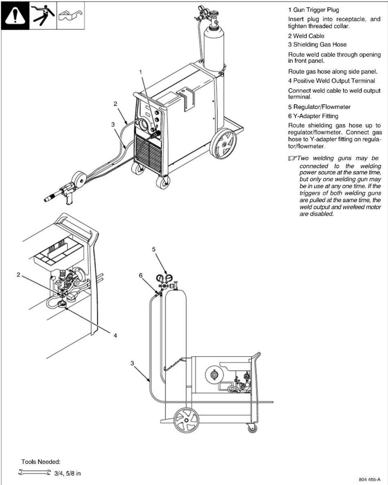
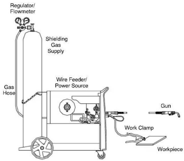
8-1. Typical MIG Process Connections
Weld current can damage electronic parts in vehicles. Disconnect both battery cables before welding on a vehicle. Place work clamp as close to the weld as possible.
light mig 11/03 / Ref. 802 064-D
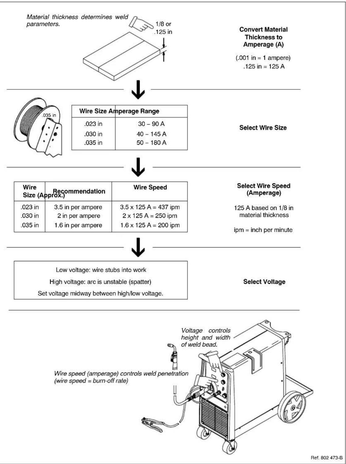
8-2. Typical MIG Process Control Settings
NOTE

These settings are guidelines only. Material and wire type, joint design, fitup, position, shielding gas, etc. affect settings. Test welds to be sure they comply to specifications.
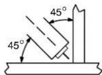
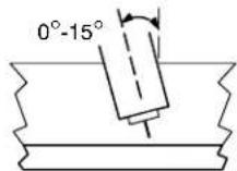
8-3. Holding And Positioning Welding Gun
NOTE

Welding wire is energized when gun trigger is pressed. Before lowering helmet and pressing trigger, be sure wire is no more than 1/2 in (13 mm) past end of nozzle, and tip of wire is positioned correctly on seam.
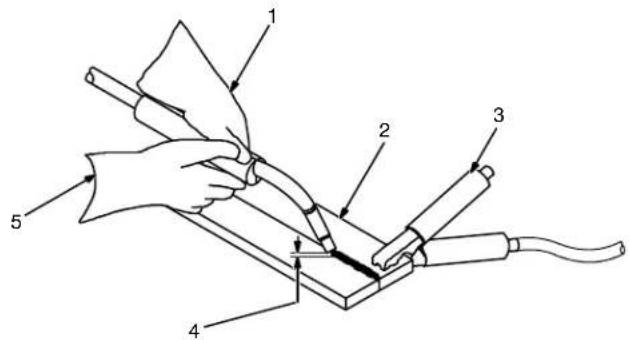
1 Hold Gun and Control Gun Trigger
2 Workpiece
3 Work Clamp
4 Electrode Extension (Stickout) 1/4 to 1/2 in (6 To 13 mm)
5 Cradle Gun and Rest Hand on Workpiece
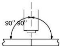
End View Of Work Angle
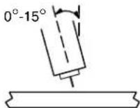
Side View Of Gun Angle
GROOVE WELDS
End View Of Work Angle
Side View Of Gun Angle
FILLET WELDS
S-0421-A
8-4. Conditions That Affect Weld Bead Shape
NOTE

Weld bead shape depends on gun angle, direction of travel, electrode extension (stickout), travel speed, thickness of base metal, wire feed speed (weld current), and voltage.
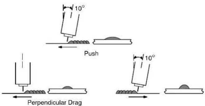
GUN ANGLES AND WELD BEAD PROFILES
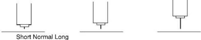
ELECTRODE EXTENSIONS (STICKOUT)
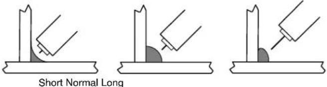
FILLET WELD ELECTRODE EXTENSIONS (STICKOUT)

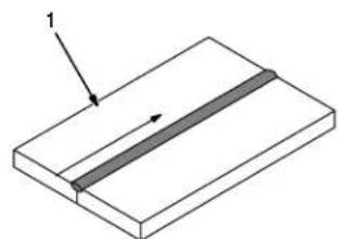
GUN TRAVEL SPEED
S-0634
8-5. Gun Movement During Welding
NOTE

Normally, a single stringer bead is satisfactory for most narrow groove weld joints; however, for wide groove weld joints or bridging across gaps, a weave bead or multiple stringer beads works better.
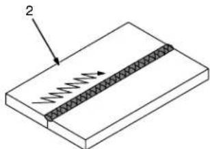
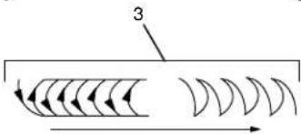
1 Stringer Bead - Steady
Movement Along Seam
2 Weave Bead - Side To Side
Movement Along Seam
3 Weave Patterns
Use weave patterns to cover a wide area in one pass of the electrode.
S-0054-A
8-6. Poor Weld Bead Characteristics
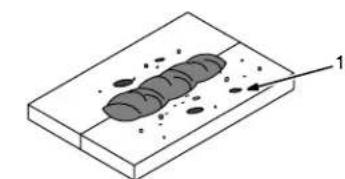
1 Large Spatter Deposits
2 Rough, Uneven Bead
3 Slight Crater During Welding
4 Bad Overlap
5 Poor Penetration
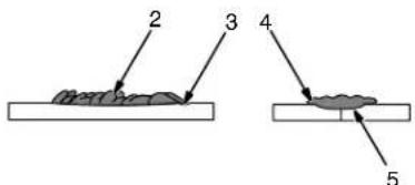
S-0053-A
8-7. Good Weld Bead Characteristics
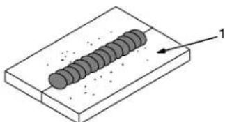
1 Fine Spatter
2 Uniform Bead
3 Moderate Crater During Welding
Weld a new bead or layer for each
1/8 in (3.2mm) thickness in metals being welded.
4 No Overlap
5 Good Penetration into Base Metal
S-0052-B
8-8. Troubleshooting - Excessive Spatter
| Excessive Spatter - scattering of molten metal particles that cool to solid form near weld bead. S-0636 | |
| Possible Causes Corrective Actions | |
| Wire feed speed too high. Select lower wire feed speed. | |
| Voltage too high. Select lower voltage range. | |
| Electrode extension (stickout) too long. Use shorter electrode extension (stickout). | |
| Workpiece dirty. | Remove all grease, oil, moisture, rust, paint, undercoating, and dirt from work surface before welding. |
| Insufficient shielding gas at welding arc. | Increase flow of shielding gas at regulator/flowmeter and/or prevent drafts near welding arc. |
| Dirty welding wire. Use clean, dry welding wire. | |
| Eliminate pickup of oil or lubricant on welding wire from feeder or liner. | |
8-9. Troubleshooting - Porosity
| Possible Causes Corrective Actions | |
| Insufficient shielding gas at welding arc. | Increase flow of shielding gas at regulator/flowmeter and/or prevent drafts near welding arc. |
| Remove spatter from gun nozzle. | |
| Check gas hoses for leaks. | |
| Place nozzle 1/4 to 1/2 in (6-13 mm) from workpiece. | |
| Hold gun near bead at end of weld until molten metal solidifies. | |
| Wrong gas. Use welding grade shielding gas; change to different gas. | |
| Dirty welding wire. Use clean, dry welding wire. | |
| Eliminate pick up of oil or lubricant on welding wire from feeder or liner. | |
| Workpiece dirty. | Remove all grease, oil, moisture, rust, paint, coatings, and dirt from work surface before welding. |
| Use a more highly deoxidizing welding wire (contact supplier). | |
| Welding wire extends too far out of nozzle. | Be sure welding wire extends not more than 1/2 in (13 mm) beyond nozzle. |
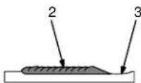
8-10. Troubleshooting - Excessive Penetration
| Excessive Penetration Good Penetration | |
| Possible Causes Corrective Actions | |
| Excessive heat input. Select lower voltage range and reduce wire feed speed. | |
| Increase travel speed. |
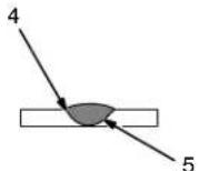
8-11. Troubleshooting - Lack Of Penetration
| Lack of Penetration Good Penetration | |
| Possible Causes Corrective Actions | |
| Improper joint preparation. | Material too thick. Joint preparation and design must provide access to bottom of groove while maintaining proper welding wire extension and arc characteristics. |
| Improper weld technique. | Maintain normal gun angle of 0 to 15 degrees to achieve maximum penetration. |
| Keep arc on leading edge of weld puddle. | |
| Be sure welding wire extends not more than 1/2 in (13 mm) beyond nozzle. | |
| Insufficient heat input. | Select higher wire feed speed and/or select higher voltage range. |
| Reduce travel speed. | |
8-12. Troubleshooting - Incomplete Fusion
| Incomplete Fusion - failure of weld metal to fuse completely with base metal or a preceding weld bead. base metal or a preceding weld bead. S-0637 | |
| Possible Causes Corrective Actions | |
| Workpiece dirty. | Remove all grease, oil, moisture, rust, paint, undercoating, and dirt from work surface before welding. |
| Insufficient heat input. | Select higher voltage range and/or adjust wire feed speed. |
| Improper welding technique. Place stringer b | lead in proper location(s) at joint during welding. |
| Adjust work angle or widen groove to access bottom during welding. | |
| Momentarily hold arc on groove side walls when using weaving technique. | |
| Keep arc on leading edge of weld puddle. | |
| Use correct gun angle of 0 to 15 degrees. | |
8-13. Troubleshooting - Burn-Through
| Burn-Through - weld metal melting completely through base metal resulting in holes where no metal remains. S-0640 | |
| Possible Causes Corrective Actions | |
| Excessive heat input. Select lower voltage range and reduce wire feed speed. | |
| Increase and/or maintain steady travel speed. |
8-14. Troubleshooting - Waviness Of Bead
| Waviness Of Bead - weld metal that is not parallel and does not cover joint formed by base metal. S-0641 | |
| Possible Causes Corrective Actions | |
| Welding wire extends too far out of nozzle. | Be sure welding wire extends not more than 1/2 in (13 mm) beyond nozzle. |
| Unsteady hand. Support hand on solid surface or use two hands. | |
8-15. Troubleshooting - Distortion
| Distortion - contraction of weld metal during welding that forces base metal to move. base metal moves in the direction of the weld bead. | |
| Possible Causes Corrective Actions | |
| Excessive heat input. Use restraint (clamp) to | hold base metal in position. |
| Make tack welds along joint before starting welding operation. | |
| Select lower voltage range and/or reduce wire feed speed. | |
| Increase travel speed. | |
| Weld in small segments and allow cooling between welds. | |
8-16. Common MIG Shielding Gases
This is a general chart for common gases and where they are used. Many different combinations (mixtures) of shielding gases have been developed over the years. The most commonly used shielding gases are listed in the following table.
| Gas | Application | |||
| Spray Arc Steel Short | Circuiting Steel | Short Circuits Stainless Steel | Aluminum | |
| Argon X | ||||
| Argon + 25% CO2 | X | |||
| 80% or greater Argon + balance CO2 or Oxygen | X | X1 | ||
| 100% CO2 | X | |||
| Tri-Mix2 | X | |||
1 Limited short circuiting use
2 90% HE + 7-1/2% AR + 2-1/2% CO
8-17. Troubleshooting Guide For Semiautomatic Welding Equipment
| Problem Probable Cause | Remedy | |
| Wire feed motor operates, but wire does not feed. | Too little pressure on wire feed rolls. Increase pressure setting on wire feed rolls. | |
| Incorrect wire feed rolls. | Check size stamped on wire feed rolls, replace to match wire size and type if necessary. | |
| Wire spool brake pressure too high. Decrease brake pressure on wire spool. | ||
| Restriction in the gun and/or assembly. | Check and replace cable, gun, and contact tip if damaged. Check size of contact tip and cable liner, replace if necessary. | |
| Wire curling up in front of the wire feed rolls (bird nesting). | Too much pressure on wire feed rolls. | Decrease pressure setting on wire feed rolls. |
| Incorrect cable liner or gun contact tip size. | Check size of contact tip and check cable liner length and diameter, replace if necessary. | |
| Gun end not inserted into drive housing properly. | Loosen gun securing bolt in drive housing and push gun end into housing just enough so it does not touch wire feed rolls. | |
| Dirty or damaged (kinked) liner. | Replace liner. | |
| Wire feeds, but no gas flows. | Gas cylinder empty. | Replace empty gas cylinder. |
| Gas nozzle plugged. | Clean or replace gas nozzle. | |
| Gas cylinder valve not open or flowmeter not adjusted. | Open gas valve at cylinder and adjust flow rate. | |
| Restriction in gas line. | Check gas hose between flowmeter and wire feeder, and gas hose in gun and cable assembly. | |
| Loose or broken wires to gas solenoid. | Have Factory Authorized Service Agent repair wiring. | |
| Gas solenoid valve not operating. | Have Factory Authorized Service Agent replace gas solenoid valve. | |
| Incorrect primary voltage connected to welding power source. | Check primary voltage and relink welding power source for correct voltage. | |
| Problem RemedyProbable Cause | ||
| Welding arc not stable. | Wire slipping in drive rolls. | Adjust pressure setting on wire feed rolls. Replace worn drive rolls if necessary. |
| Wrong size gun liner or contact tip. Match liner and contact tip to wire size and type. | ||
| Incorrect voltage setting for selected wire feed speed on welding power source. | Readjust welding parameters. | |
| Loose connections at the gun weld cable or work cable. | Check and tighten all connections. | |
| Gun in poor shape or loose connection inside gun. Repair or replace gun as necessary. | ||
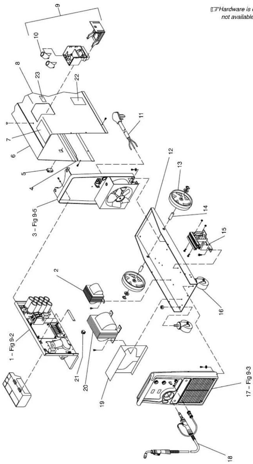
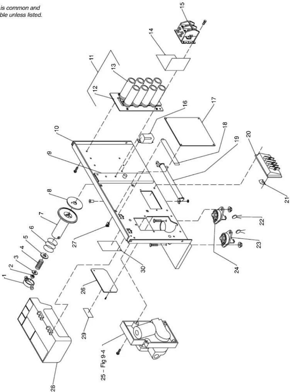
Figure 9-1. Main Assembly
803 008-B
Figure 9-1. Main Assembly
| 1 | Fig 9-2 | BAFFLE, center w/components | 1 |
| 2 | Z1 | STABILIZER | 1 |
| 3 | Fig 9-5 | PANEL, rear w/components | 1 |
| 4 | 203 481 | PANEL, side LH | 1 |
| 5 | 151 187 | LATCH, slide flush mtg hole 1.000 wide x 1.500 lg | 2 |
| 6 | 203 480 | DOOR, hinged | 1 |
| 201 202 | LABEL, parameter | 1 | |
| 7 | 134 464 | LABEL, warning general precautionary | 2 |
| 8 | +203 482 | WRAPPER | 1 |
| 9 | 200 923 | GUN/CABLE HOLDER, (consisting of) | 1 |
| 10 | 200 921 | HOLSTER, gun/cable holder | 2 |
| 11 | 188 911 | CABLE, pwr 250v 6-50p 8-10ga 3/c 12ft for 200/230 | 1 |
| 11 | 187 255 | CABLE, pwr 250v t tung 8-10ga 3/c 12ft for 230/460/575 or 230/400 | 1 |
| 199 823 | LABEL, warning electric shock power cord | 1 | |
| 12 | 146 161 | BASE | 1 |
| 13 | 186 758 | WHEEL | 2 |
| 14 | 052 692 | AXLE, running gear (consisting of) | 1 |
| 121 614 | RING, retaining ext .750 shaft x .085grv depth | 2 | |
| 15 | 200 519 | RECTIFIER, SCR main (consisting of) | 1 |
| SR1 | 197 698 | THYRISTOR, SCR module 300A 400V common anode | 1 |
| C3,4 | 031 689 | CAPACITOR, rectifier | 2 |
| T | 173 632 | THERMISTER, 30K @ 25C | 2 |
| 205 946 | FOOT, mtg rectifier | 2 | |
| PLG5 | 115 094 | HOUSING PLUG & SKTS (4 position) | 1 |
| 16 | 209 870 | CASTER, plstc swvl 4 in dia | 2 |
| 17 | Fig 9-3 | PANEL, front w/components | 1 |
| 18 | 169 596 | GUN, 12ft .030-.035 wire (see welding gun Owner's Manual) | 1 |
| 19 | 150 387 | BAFFLE, air | 1 |
| 20 | T1 222 474 | TRANSFORMER, pwr main (200/230) | 1 |
| 20 | T1 222 478 | TRANSFORMER, pwr main (230/460/575) | 1 |
| 21 | PLG2 110 760 | HOUSING RECEPTACLE & SOCKET(S harness) | 1 |
| 22 | 193 328 | LABEL, warning electric shock and incorrect input | 1 |
| 23 | 201 019 | LABEL, warning electric shock excess weight | 1 |
| PLG4 | 110 759 | HOUSING RECEPTACLE & SOCKET(Xfmr) | 1 |
| 209 123 | REGULATOR/FLOWMETER, 10-50 CFH Argon/Mixed | 1 | |
| 196 328 | CABLE, work 10' w/clamp and boot (consisting of) | 1 | |
| 130 750 | CLAMP, ground 350A | 1 | |
| 600 318 | CABLE, weld cop strd No. 3 (order by ft) | 10ft | |
| 196 318 | COVER, cable btry post blk .75 ID | 1 | |
| 144 108 | HOSE, gas | 1 | |
| ◆212 492 REGULATOR/FLOWMETER, 10-50 CFH CO 2 | 1 |
+When ordering a component originally displaying a precautionary label, the label should also be ordered.
OPTIONAL
To maintain the factory original performance of your equipment, use only Manufacturer's Suggested Replacement Parts. Model and serial number required when ordering parts from your local distributor.
Hardware is common and not available unless listed.
Figure 9-2. Baffle, Center w/Components
803007-E
Figure 9-2. Baffle, Center w/Components (Fig 9-1 Item 1)
| 1 | 058 427 | RING, retaining spool | 1 |
| 2 | 085 980 | NUT, stl hex full .625-11 | 1 |
| 3 | 605 941 | WASHER, flat stl .640 ID x 1.000 OD x 14ga thick | 1 |
| 4 | 186 437 | SPRING, cprsn .845 OD x .110 wire x 1.500 | 1 |
| 5 | 057 971 | WASHER, flat stl keyed 1.500dia x .125thk | 1 |
| 6 | 057 745 | SPRING, cprsn 2.430 OD x .090 wire x 2.500 | 1 |
| 7 | 186 435 | HUB, spool | 1 |
| 8 | 186 436 | WASHER, brake | 1 |
| 9 | 177 307 | REEL, support | 1 |
| 198425 | CAP, finishing 1.19 X .37 | 2 | |
| 198426 | WASHER, cap | 2 | |
| 10 | 211 413 | BAFFLE, center | 1 |
| 11 | 186 998 | CAPACITOR ASSEMBLY KIT, (consisting of) | 1 |
| 12 | 229 801 | KIT, capacitor bus bar and insulator | 1 |
| 083 147 | GROMMET, scr No. 8/10 panel hole .312sq .500 high | 6 | |
| 13 | C5 | CAPACITOR, elctit 15000uf 45VDC | 8 |
| 14 | 204 318 | BRACKET, mtg | 1 |
| 15 | W | CONTACTOR, def prp 25A 2P 36VDC | 1 |
| 16 | CR1 | RELAY, 24V DPDT 10A/120VAC | 1 |
| VR1 | VARISTOR, w/leads | 1 | |
| 17 | PC1 | 220 069 | 1 |
| PLG1 | HOUSING PLUG & SOCKETS | 1 | |
| PLG3 | HOUSING RECEPTACLE & SOCKETS | 1 | |
| PLG7 | HOUSING RECEPTACLE & SOCKETS | 1 | |
| PLG8 | HOUSING PLUG & SOCKETS | 1 | |
| 18 | 196 894 | COVER | 1 |
| 19 | R1 | RESISTOR, WW fxd 300W 5 ohm | 1 |
| 20 | TE1 | TERMINAL ASSEMBLY, pri 1ph double voltage (200/230 or 230/400) | 1 |
| 20 | TE1 | TERMINAL ASSEMBLY, pri 1ph triple voltage (230/460/575) | 1 |
| 21 | 038 618 | LINK, jumper term bd pri | as req. |
| 22 | C7,8 | CAPACITOR | 2 |
| 23 | POS | TERMINAL, pwr output red | 1 |
| 24 | NEG | TERMINAL, pwr output black | 1 |
| 25 | Fig 9-4 | WIRE DRIVE & GEARS | 1 |
| 26 | 188 917 | DOOR, access changeover | 1 |
| 27 | 134 201 | STAND-OFF SUPPORT, PC card | 4 |
| 28 | 197 555 | TOOL TRAY | 1 |
| 29 | 021 469 | LABEL, warning high voltage | 1 |
| 30 | 199 824 | LABEL, warning electric shock and pinch points | 1 |
+When ordering a component originally displaying a precautionary label, the label should also be ordered. To maintain the factory original performance of your equipment, use only Manufacturer's Suggested Replacement Parts. Model and serial number required when ordering parts from your local distributor.
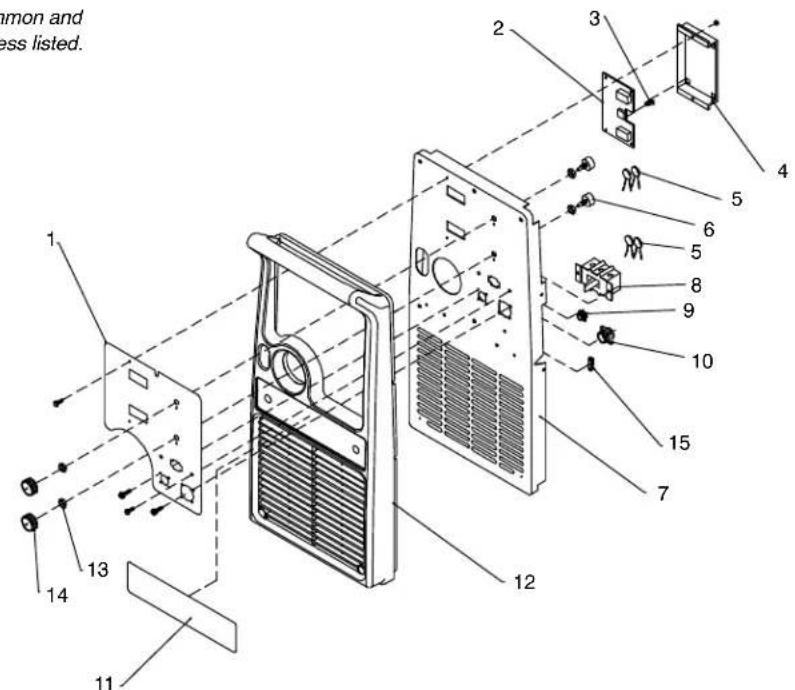
Figure 9-3. Panel, Front w/Components (Fig 9-1 Item 17)
| 1 | 208 357 | LABEL, nameplate | 1 |
| 2 | 224 075 | CIRCUIT CARD ASSY, display | 1 |
| PLG9 | 115 094 | PLUG w/SOCKETS | 1 |
| 3 | 134 201 | STANDOFF | 4 |
| 4 | 196 801 | BRACKET, mtg display board | 1 |
| 5 C9,10,18, | |||
| 19,20 | 136 735 | CAPACITOR, cer disc .uf 500VDC | 5 |
| 6 R2,3 | 208 207 | POTENTIOMETER | 2 |
| PLG7 | 115 092 | HOUSING RECEPTACLE & SOCKETS | 1 |
| 7 | 208 166 | PANEL, front | 1 |
| 8 S1 | 128 755 | SWITCH, tgl | 1 |
| 9 RC1 | 048 282 | RECEPTACLE w/SOCKETS | 1 |
| 10 RC7 | 190 363 | RECEPTACLE w/SOCKETS | 1 |
| 11 | 208 167 | LABEL, logo | 1 |
| 12 | 208 164 | PANEL, front bezel | 1 |
| 13 | 193 632 | NUT, 375-16 .56 hex .34H stl | 2 |
| 14 | 207 077 | KNOB, pointer 1.625dia | 2 |
| 15 | 129 524 | TERM, frict 250 x 032 | 1 |
Hardware is common and not available unless listed.
Figure 9-3. Panel, Front w/Components
803 307-A
To maintain the factory original performance of your equipment, use only Manufacturer's Suggested Replacement Parts. Model and serial number required when ordering parts from your local distributor.
Figure 9-4. Wire Drive And Gears (Fig 9-2 Item 26)
| 1 | 602 009 | SCREW, .250-20 x 1.25 soc hd gr 8 | 1 |
| 2 | 172 075 | CARRIER, drive roll w/components | 1 |
| 3 | 166 072 | SPACER, gear | 1 |
| 4 | 010 224 | PIN, spring CS .187 x 1.000 | 1 |
| 5 | 182 788 | HOUSING, adapter gun/feeder | 1 |
| 6 | 225 718 | FASTENER, pinned | 1 |
| 7 | 196 896 | CUP, spring | 1 |
| 8 | 196 897 | SPRING, cprsn .695 OD x .095 wire | 1 |
| 9 | 196 895 | KNOB, tension adj | 1 |
| 10 | 166 071 | LEVER, mtg pressure gear | 1 |
| 11 | 204 510 | PIN, hinge | 1 |
| 12 | 151 828 | PIN, cotter hair .054 x .750 | 1 |
| 13 | 173 616 | COVER, right angle motor | 1 |
| 14 | M 225 341 | MOTOR, gear 24VDC (consisting of) | 1 |
| 193 633 | KEY, woodruff .118 x .380 | 1 | |
| 193 634 | WASHER, wave .405 ID x .740 OD | 2 | |
| 193 635 | RING, rtng ext .394 shaft x | 1 | |
| 15 | 079 633 | FITTING, hose brs barbed M 3/16tbg | 1 |
| 16 | 601 966 | SCREW, .375-16 x 1.25hexhd | 2 |
| 17 | 604 538 | WASHER, flat stl SAE .312 | 1 |
| 18 | 204 585 | KNOB, fluted | 1 |
| 19 | 173 619 | CARRIER, drive roll w/components | 1 |
| 20 | 174 609 | SCREW, M 4-.7 x 12 | 1 |
| 21 | 174 610 | SCREW, M 6-1.0 x 20 soc hd | 3 |
| 22 | 192 029 | WASHER, flat .250 ID x .437 OD | 3 |
| 23 | 173 620 | BUSHING, motor mtg | 3 |
| 24 | 602 243 | WASHER, flat .438 ID X 1.00 OD | 1 |
| 25 | 602 213 | WASHER, lock .380 ID X .683 OD | 1 |
| 26 | *221 912 | GUIDE,WIRE INLET | 1 |
| 203526 | ROLL,DRIVE V GROOVE .030/.035 COMB WIRE | 2 |
see Section 9-6 Drive Roll & Wire Guide Kits.
Hardware is common and not available unless listed.
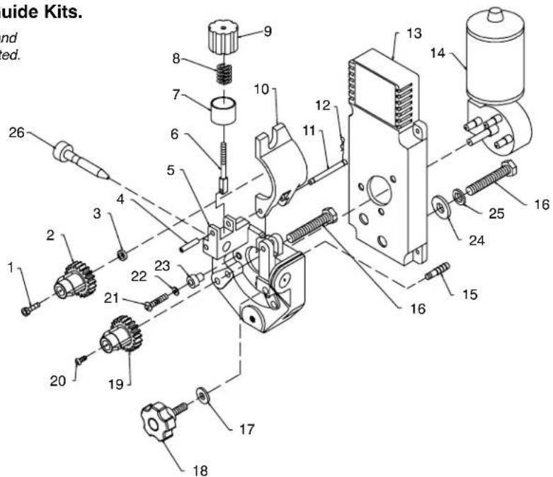
Figure 9-4. Wire Drive And Gears
*Recommended Spare Parts.
To maintain the factory original performance of your equipment, use only Manufacturer's Suggested Replacement Parts. Model and serial number required when ordering parts from your local distributor.
Figure 9-5. Panel, Rear w/Components (Fig 9-1 Item 3)
| 1 | 148 809 | BLADE, fan 9 in 5wg 34deg .309 bore CCW | 1 |
| 2 | 188 706 | MOTOR, fan 230V 50/60 Hz 1550RPM .312dia shaft | 1 |
| 3 | 203 711 | WINDTUNNEL | 1 |
| 4 | GS1 | VALVE, 34VDC 2 way custom port 1/8 orf | 1 |
| 5 | 203 478 | PANEL, rear | 1 |
| 6 | 169 654 | +BRACKET, support tank | 1 |
| 200 285 | LABEL, warning cylinder may | 1 | |
| 7 | 188 441 | CHAIN, weldless 2/0 x 31.000 lg | 1 |
| 8 | 137 761 | NUT, 750NPT 1.31hex .27H nyl blk | 1 |
| 9 | 604 102 | CONNECTOR, clamp cable .690/1.070 | 1 |
Hardware is common and not available unless listed.
Figure 9-5. Panel, Rear w/Components
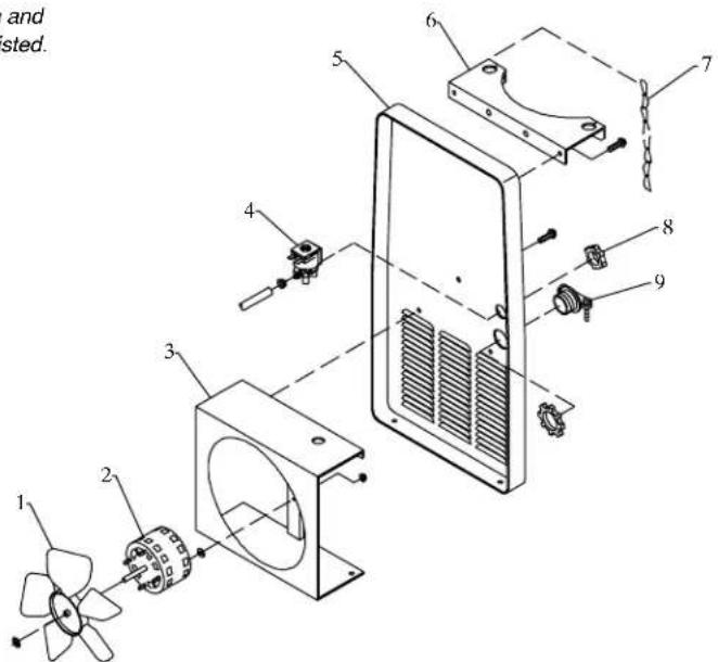
Ref.803 011
+When ordering a component originally displaying a precautionary label, the label should also be ordered. To maintain the factory original performance of your equipment, use only Manufacturer's Suggested Replacement Parts. Model and serial number required when ordering parts from your local distributor.
9-6. Drive Roll And Wire Guide Kits
Note
Base selection of drive rolls upon the following recommended usages:
1 V-Grooved rolls for hard wire.
2 U-Grooved rolls for soft and soft shelled cored wires.
3 U-Cogged rolls for extremely soft shelled wires (usually hard surfacing types).
4 V-Knurled rolls for hard shelled cored wires.
5 Drive roll types may be mixed to suit particular requirements (example: V-Knurled roll in combination with U-Grooved).
| Wire Diameter | Kit No. | Drive Roll | Inlet Wire Guide | |||
| Fraction Decimal Metric | Part No. Type | |||||
| .023/.025 in. | .023/.025 in. | 0.6 mm | 087 131 | 087 130 | V-Grooved | 056 192 |
| .030/.035 in. | .030/.035 in. | 0.8/0.9 mm | 204 579 | 203 526 | V-Grooved | 056 192 |
| .030 in. | .030 in. | 0.8 mm | 079 594 | 053 695 | V-Grooved | 056 192 |
| .035 in. | .035 in. | 0.9 mm | 079 595 | 053 700 | V-Grooved | 056 192 |
| .045 in. | .045 in. | 1.2 mm | 079 596 | 053 697 | V-Grooved | 056 193 |
Notes
Notes
Notes
Warranty Questions?
Call
1-800-4-A-MILLER
for your local
Miller distributor.
Your distributor also gives you ...
Service
You always get the fast, reliable response you need. Most replacement parts can be in your hands in 24 hours.
Support
Need fast answers to the tough welding questions? Contact your distributor. The expertise of the distributor and Miller is there to help you, every step of the way.

Miller

Effective January 1, 2006
(Equipment with a serial number preface of "LG" or newer)
This limited warranty supersedes all previous Miller warranties and is exclusive with no other guarantees or warranties expressed or implied.
LIMITED WARRANTY - Subject to the terms and conditions below, Miller Electric Mfg. Co., Appleton, Wisconsin, warrants to its original retail purchaser that new Miller equipment sold after the effective date of this limited warranty is free of defects in material and workmanship at the time it is shipped by Miller. THIS WARRANTY IS EXPRESSLY IN LIEU OF ALL OTHER WARRANTYES, EXPRESS OR IMplied, INCLUDING THE WARRANTYES OF MERCHANTABILITY AND FITNESS.
Within the warranty periods listed below, Miller will repair or replace any warranted parts or components that fail due to such defects in material or workmanship. Miller must be notified in writing within thirty (30) days of such defect or failure, at which time Miller will provide instructions on the warranty claim procedures to be followed.
Miller shall honor warranty claims on warranted equipment listed below in the event of such a failure within the warranty time periods. All warranty time periods start on the date that the equipment was delivered to the original retail purchaser, or one year after the equipment is sent to a North American distributor or eighteen months after the equipment is sent to an International distributor.
-
5 Years Parts - 3 Years Labor
-
Original main power rectifiers
2.3 Years - Parts and Labor
- Transformer/Rectifier Power Sources
- Plasma Arc Cutting Power Sources
- Process Controllers
- Semi-Automatic and Automatic Wire Feeders
- Inverter Power Sources (Unless Otherwise Stated)
- Water Coolant Systems (Integrated)
- Intellitig
- Engine Driven Welding Generators
(NOTE: Engines are warranted separately by the engine manufacturer.)
3.1 Year — Parts and Labor Unless Specified
- Motor Driven Guns (w/exception of Spoolmate Spoolguns)
- Positioners and Controllers
- Automatic Motion Devices
- RFCS Foot Controls
-
Induction Heating Power Sources, Coolers, and Electronic Controls/Recorders
-
Water Coolant Systems (Non-Integrated)
-
Flow gauge and Flowmeter Regulators (No Labor)
-
HF Units
-
Grids
-
Spot Welders
-
Load Banks
-
Arc Stud Power Sources & Arc Stud Guns
-
Racks
-
Running Gear/Trailers
-
Plasma Cutting Torches (except APT & SAF Models)
-
Field Options (NOTE: Field options are covered under True Blue® for the remaining warranty period of the product they are installed in, or for a minimum of one year — whichever is greater.)
-
Bernard-Branded Mig Guns (No Labor)
- Weldcraft-Branded TIG Torches (No Labor)
- Subarc Wire Drive Assemblies
4.6 Months — Batteries
5.90 Days - Parts
* MIG Guns/TIG Torches and Subarc (SAW) Guns
- Induction Heating Coils and Blankets, Cables, and Non-Electronic Controls
- APT & SAF Model Plasma Cutting Torches
*Remote Controls - Accessory (Kits)
- Replacement Parts (No labor)
- Spoolmate Spoolguns
*Canvas Covers
Miller's True Blue® Limited Warranty shall not apply to:
- Consumable components; such as contact tips, cutting nozzles, contactors, brushes, slip rings, relays or parts that fail due to normal wear. (Exception: brushes, slip rings, and relays are covered on Bobcat, Trailblazer, and Legend models.)
- Items furnished by Miller, but manufactured by others, such as engines or trade accessories. These items are covered by the manufacturer's warranty, if any.
- Equipment that has been modified by any party other than Miller, or equipment that has been improperly installed, improperly operated or misused based upon industry standards, or equipment which has not had reasonable and necessary maintenance, or equipment which has been used for operation outside of the specifications for the equipment.
MILLER PRODUCTS ARE INTENDED FOR PURCHASE AND USE BY COMMERCIAL/INDUSTRIAL USERS AND PERSONS TRAINED AND EXPERIENCED IN THE USE AND MAINTENANCE OF WELDING EQUIPMENT.
In the event of a warranty claim covered by this warranty, the exclusive remedies shall be, at Miller's option: (1) repair; or (2) replacement; or, where authorized in writing by Miller in appropriate cases, (3) the reasonable cost of repair or replacement at an authorized Miller service station; or (4) payment of or credit for the purchase price (less reasonable depreciation based upon actual use) upon return of the goods at customer's risk and expense. Miller's option of repair or replacement will be F.O.B., Factory at Appleton, Wisconsin, or F.O.B. at a Miller authorized service facility as determined by Miller. Therefore no compensation or reimbursement for transportation costs of any kind will be allowed.
TO THE EXTENT PERMITTED BY LAW, THE REMEDIES PROVIDED HEREIN ARE THE SOLE AND EXCLUSIVE REMEDIES. IN NO EVENT SHALL MILLER BE LIABLE FOR DIRECT, INDIRECT, SPECIAL, INCIDENTAL OR CONSEQUENTIAL DAMAGES (INCLUDING LOSS OF PROFIT), WHETHER BASED ON CONTRACT, TORT OR ANY OTHER LEGAL THEORY.
ANY EXPRESS WARRANTY NOT PROVIDED HEREIN AND ANY IMPLIED WARRANTY, GUARANTY OR REPRESENTATION AS TO PERFORMANCE, AND ANY REMEDY FOR BREACH OF CONTRACT TORT OR ANY OTHER LEGAL THEORY WHICH, BUT FOR THIS PROVISION, MIGHT ARE ATRIGHE BY IMPLICATION, OPERATION OF LAW, CUSTOM OF TRADE OR COURSE OF DEALING, INCLUDING ANY IMPLIED WARRANTY OF MERCHANTABILITY OR FITNESS FOR PARTICULAR PURPOSE, WITH RESPECT TO ANY AND ALL EQUIPMENT FURNISHED BY MILLER IS EXCLUDING AND DISCLAIMED BY MILLER.
Some states in the U.S.A. do not allow limitations of how long an implied warranty lasts, or the exclusion of incidental, indirect, special or consequential damages, so the above limitation or exclusion may not apply to you. This warranty provides specific legal rights, and other rights may be available, but may vary from state to state.
In Canada, legislation in some provinces provides for certain additional warranties or remedies other than as stated herein, and to the extent that they may not be waived, the limitations and exclusions set out above may not apply. This Limited Warranty provides specific legal rights, and other rights may be available, but may vary from province to province.
miller_warr 2006-01

Owner's Record
Please complete and retain with your personal records.
Model Name Serial/Style Number
Purchase Date (Date which equipment was delivered to original customer.)
Distributor
Address
City
State Zip

For Service
Contact a DISTRIBUTOR or SERVICE AGENCY near you.
Always provide Model Name and Serial/Style Number.
| Contact your Distributor for: | Welding Supplies and Consumables Options and Accessories Personal Safety Equipment Service and Repair Replacement Parts Training (Schools, Videos, Books) Technical Manuals (Servicing Information and Parts) Circuit Diagrams Welding Process Handbooks To locate a Distributor or Service Agency visit www.millerwelds.com or call 1-800-4-A-Miller |
| Contact the Delivering Carrier to: | File a claim for loss or damage during shipment. For assistance in filing or settling claims, contact your distributor and/or equipment manufacturer's Transportation Department. |
Miller Electric Mfg. Co.
An Illinois Tool Works Company
1635 West Spencer Street
Appleton, WI 54914 USA
International Headquarters-USA
USA Phone: 920-735-4505 Auto-Attended
USA & Canada FAX: 920-735-4134
International FAX: 920-735-4125
European Headquarters -
United Kingdom
FAX:44(0)1204-598066
www.MillerWelds.com

Miller