
SW 2000 - Power inverter AEG - Free user manual and instructions
Find the device manual for free SW 2000 AEG in PDF.
| Product type | Pure sine wave power inverter |
| Brand | AEG |
| Model | SW 2000 (art. 97123) |
| Nominal input voltage | 12 V DC |
| Output voltage | 230 V AC / 50 Hz |
| Waveform | Pure sine wave |
| Continuous power | 2000 W |
| Peak power (0.1 s) | 4000 W |
| Dimensions (L x W x H) | 530 x 260 x 85 mm |
| Weight | 6.60 kg |
| Ambient temperature range | 0 °C to 30 °C |
| Overvoltage protection | 15.5 V ±0.5 V |
| Undervoltage protection | 10 V ±0.5 V |
| Overload protection | 2200 W ±100 W |
| Overheat protection | 68 °C (automatic shutdown) |
| Short circuit protection | Yes (automatic shutdown) |
| Fuses | 8 x 30 A |
| USB output | 5 V / max. 500 mA (USB 2.0) |
| Included accessories | Remote control module, cables with ring terminals |
| Cleaning | Slightly damp cloth, no abrasives |
| Safety | Multiple protections (overvoltage, undervoltage, overload, overheat, short circuit) |
| Repairability | Repairs by qualified electrician only |
| Intended use | Fixed installation in vehicles, caravans, boats |
Frequently Asked Questions - SW 2000 AEG
User questions about SW 2000 AEG
0 question about this device. Answer the ones you know or ask your own.
Ask a new question about this device
Download the instructions for your Power inverter in PDF format for free! Find your manual SW 2000 - AEG and take your electronic device back in hand. On this page are published all the documents necessary for the use of your device. SW 2000 by AEG.
USER MANUAL SW 2000 AEG
Read these instructions before using the charger. Follow all instructions and recommendations.
FR - Page 31
Specific technical data (modified sinusoidal wave) 20
Specific technical data (pure sinusoidal wave). 20
Power sources suitable for connection. 20
Connectible devices 20
Intended sites 21
Safety 21
Technical features. 23
Product Overview. 24
Technology 25
Installation & connection 25
Preparation. 25
Voltage converter installation. 26
Remote control module installation 26
Connection to the power source. 26
To a car battery. 26
Use 26
Troubleshooting 28
Cleaning, care and maintenance 29
Service. 29
Disposal 29
INTRODUCTION
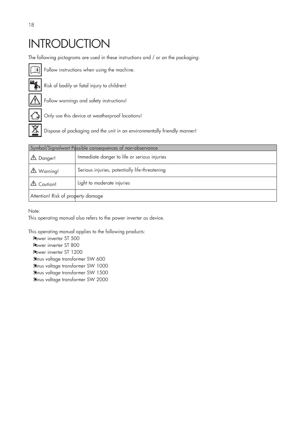
The following pictograms are used in these instructions and / or on the packaging:

Follow instructions when using the machine.

Risk of bodily or fatal injury to children!

Follow warnings and safety instructions!

Only use this device at weatherproof locations!

Dispose of packaging and the unit in an environmentally friendly manner!
| Symbol/Signalwort Possible consequences of non-observance | |
| Danger! | Immediate danger to life or serious injuries |
| Warning! | Serious injuries, potentially life-threatening |
| Caution! | Light to moderate injuries |
| Attention! Risk of property damage | |
Note:
This operating manual also refers to the power inverter as device.
This operating manual applies to the following products:
Power inverter ST 500
Power inverter ST 800
Power inverter ST 1200
Sinus voltage transformer SW 600
Sinus voltage transformer SW 1000
Sinus voltage transformer SW 1500
Sinus voltage transformer SW 2000
Normal use
The power inverter is intended to convert 12V direct current voltage to
alternating current voltage 230V / 50Hz and/or
direct current voltage of 5V / .500mA (2.0 USB).
The power inverter is only intended for permanent installation.
This device is not intended for use by children or persons with limited mental capacity or lacking experience and/or lacking expertise. Children should be supervised to ensure they do not play with the device.
This device is not intended for commercial use.
Any other use or modification of the device is considered improper and involves significant risks. The manufacturer assumes no liability for damages due to improper use.
Contents
Be sure to verify contents immediately upon opening the product. Check the product and all parts for damage. Do not use a defective product or parts.
Power inverter with 12V connector
Remote control module
2 cables with ring lugs/clamps
Operating instructions
Please make all relevant documentation available to other users!
Technical data
| Nominal input voltage 12 V DC / 50 Hz | |
| Output voltage 230 V | |
| Wave form Sinusoidal wave | |
| Ambient temperature 0°C - 30°C | |
| Over-voltage protection | 15,5 V ±0,5 V |
| Under-voltage protection | 10 V ±0,5 V |
| Over-heating protection | ±68 °C |
| Input voltage range 10 - 15 V DC | |
| Low battery shutdown | 10 V DC ±0,5 V |
Specific technical data (modified sinusoidal wave)
| Model ST 500 ST 800 ST 1200 | |||
| Item number 97115 97116 97117 | |||
| Continuous power output 500 W 800 W 1200 W | |||
| Peak power output (0.1 sec.) 1000 W 1600 W 2400 W | |||
| Dimensions in mm 240 x 180 x 85 308 x 180 x 85 378 x 180 x 85 | |||
| Weight 1,50 kg 2,17 kg 2,70 kg | |||
| Overload protection | 550 W ±40 W | 880 W ±60 W | 1320W ±100 W |
| Fuse 2x 30 A 3x 30 A 4x 40 A | |||
Specific technical data (pure sinusoidal wave)
| Model | SW 600 | SW 1000 | SW 1500 | SW 2000 |
| Item number | 97120 | 97121 | 97122 | 97123 |
| Continuous power output 600 W | 1000 W 1500 W | 2000 W | ||
| Peak power output (0.1 sec.) | 1200 W 2000 W | 3000 W | 4000 W | |
| Dimensions in mm | 378 × 180 × 85 | 400 × 180 × 85 | 408 × 180 × 85 | 530 × 2600 × 85 |
| Weight | 2,72 kg | 3,30 kg | 4,65 kg | 6,60 kg |
| Overload protection | 660 W ±40 W | 1100 W ±100 W | 1650 W ±120 W | 2200 W ±100 W |
| Fuse | 2× 60 A | 4× 40 A | 6× 30 A | 8× 30 A |
Power sources suitable for connection
The voltage converter is intended for connection to power sources with 12V direct current. It must have sufficient capacity for the consumers connected to the converter.
To calculate the required capacity, divide the consumer load by the voltage.
Example: Consumer load 180 W : 12 V = 15 A
Connecting to power sources with an output voltage other than 12V direct current is prohibited and improper.
Connectible devices
| Allowed | Not allowed |
| Devices with a total rated voltage • ST 500 (97115) < 500 W • ST 800 (97116) < 800 W • ST 1200 (97117) < 1200 W • SW 600 (97120) < 600 W • SW 1000 (97121) < 1000 W • SW 1500 (97122) < 1500 W • SW 2000 (97123) < 2000 W | Devices with a total rated voltage • ST 500 (97115) > 500 W • ST 800 (97116) > 800 W • ST 1200 (97117) > 1200 W • SW 600 (97120) > 600 W • SW 1000 (97121) > 1000 W • SW 1500 (97122) > 1500 W • SW 2000 (97123) > 2000 W |
| (also see “Technical Data”). | (also see “Technical Data”). |
Note regarding Item 97115, 97116, 97117
The voltage converter provides a modified sinusoidal voltage. To prevent consequential loss, please verify the device to be powered is suitable (also see "Technology").
Intended sites
The power inverter is intended for installation in:
Automobiles and lorries
Caravans
Boats
Do not place the power inverter:
near heat sources (radiators, direct sunlight), flammable materials, battery compartment or starter battery,
moist locations or locations exposed to dripping or splashing water,
in environments with explosion hazards.
SAFETY
Read all safety guidelines and instructions. Non-compliance with safety guidelines and instructions can cause electric shock, fire and / or serious injury. Keep all safety guidelines and instructions for future reference.

Warning!

Risk of bodily or fatal injury to children! Risk of suffocation or strangulation! Keep the machine out of the reach of children. Children are unable to assess the risks associated with use of this product!

Danger! Damaged leads may cause fatal electric shock. Discontinue use if leads are damaged.
The manufacture is not responsible for damages caused by:
improper connection and/or operation.
External forces, damage to the device and/or damage to parts of the device due to mechanical impacts or overload.
Any type of modifications to the device. Using the device for purposes not described in these operating instructions.
Subsequent damages from improper and/or incorrect use and/or defective batteries.
Moisture and/or inadequate ventilation.
Unauthorised opening of the device. This will void the warranty.


Risk of fire and electric shock!
Failure to follow all instructions listed below may result in electric shock, fire, serious injury and damage to property.
Never use the cable to carry or pull the device.
Only unplug the cable from the outlet by the plug. The cable could be damaged.
If cables are to be routed through sharp-edged walls, e.g. metal walls, use empty tubes or cables ducts to avoid damaging the cables.
Do not route 230 V main cables and 12 V/24 DC cables in the same empty tube (cable duct).
Do not use device if damaged. Damage to the device or the charging cable increases the risk of electrical shock.
Route the electrical cable so that it is not possible to trip over them and to prevent them being damaged.
Maintenance work must be done by qualified electricians.
Ensure that the device is always stored in a safe place. Do no expose the device to rain or wet conditions. Avoid pouring or dripping water or other liquids over it. If water penetrates electrical devices, the risk of electric shock increases.
Ensure that all plugs and cables are free of moisture. Never connect the device to the mains with wet or moist hands.
Only connect 230V devices with permitted power plugs.
Never create a short circuit or bridge on the inputs and outputs of the power inverter using foreign objects. Only use protective contact plugs or spade connectors to connect external appliances to the output sockets.
Do not attempt to disassemble or repair the device. Immediately have the device repaired or replaced by a specialty shop if defective.
Do not cover the device as it may be damaged from extreme heating.
Immediately stop using the device if you notice smoke or an unusual odour.

Risk of injury!
Keep the device's cables away from the steering wheel, gearshift, and gas- and brake pedals. Position the device so as not to hinder you in operating the vehicle.
Do not insert objects through the ventilation slots.
Please also note the operating instructions of connected devices.
TECHNICAL FEATURES
The power inverter is equipped with technical features to protect itself and/or connected external devices.
| Feature LED display | Acoustic alarm Description | ||
| Over-voltage protection | LED display shows "HiVi" red LED lights up | sounds | The input voltage exceeds 15.5 V 0.5 V the power inverter will switch off. The power inverter will switch back on when the input voltage again reaches the rated voltage. |
| Low-voltage protection (protection for the battery of the vehicle) | LED display reads "LoVi" red LED lights up | sounds | The input voltage drops below 10.5 V ± 0,5 V. When the input voltage returns to the rated voltage, the voltage transformer automatically switches back on. |
| Short circuit protection | LED display reads "ShCt" red LED lights up | sounds | Automatic cut off |
| Overheating protection | LED display reads "OvHt" red LED lights up | sounds | The indoor temperature rises above approx. 68 °C the unit will automatically switch off. The temperature drops below 35 °C, press the Power button (9, 19) approx. 1 sec to switch the unit back on. |
| Overload protection | LED display reads "OvHt" red LED lights up | sounds | The unit will automatically switch off. |
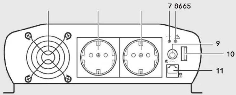
PRODUCT OVERVIEW

Item no.
97115
97116
97120
97116
97120
97116
97120
97116
97120
97116
97120
Item no.
97117, 97121
97122,97123
14
一
一
一
一
一
C
)
一
m = 311 ;
- Black connection (-)
- Red connection (+)
- Mounting rail
- Earth connection
- Fan cover
- Isolated ground receptacle
- Power LED, green
- Error LED, red
- Power button
-
USB connector
-
Remote control module connector
- Black cable with clamp (-)
- Red cable with clamp (+)
- Black cable with lugs (-)
- Red cable with lugs (+)
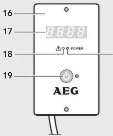
- Remote control module
- Display
- Error LED, red (Remote control module)
- Power button (Remote control module)
- Power LED, green (Remote control module)
TECHNOLOGY
Attention!
Check the properties of the device to be powered before using the voltage converter to prevent consequential damage.
There are pure or modified sinusoidal wave voltage converters.
| Model Item number | for connecting (examples) | ||
| Modified sinusoidal wave | 500 | 7115 | Power drills |
| 800 | 7116 | Computer | |
| 1200 | 7117 | Hobs | |
| Lamps, | |||
| Pans/vents | |||
| Lawn mowers | |||
| Pure sinusoidal wave | 600 | 7120 | in addition to the modified sinus- |
| 1000 | 7121 | idal wave examples | |
| 1500 | 7122 | Coffee makers | |
| 2000 | 7123 | havers | |
| Audio amplifiers | |||
INSTALLATION & CONNECTION
Preparation
Attention!
Before connecting the power inverter you must check the connections on the vehicle's battery.
the ^ 十 + ^ 十 pole on the vehicle's battery is connected to the chassis, you must not use the power converter with such vehicles.
Only use the included cables with lugs to connect to the 12 V direct current supply (e.g. automotive battery). If the cables included are too short you may also use insulated copper cables available from speciality retailers.
Keep the cable length as short as possible. The suitable cable diameter must be selected according to the length of the cable between the inverter and the power source. When in doubt please contact a speciality retailer.
Voltage converter installation
Install the power inverter with suitable screws (not included):
in sturdy and even locations,
clean, dry and non-flammable surfaces,
in well ventilated areas.
Please be sure not to cover the vents.
Remote control module installation
Mount the remote control module in a safe and accessible location using suitable screws (not included). Unwind the entire remote control module (14) cable and plug the connector into the jack (11).
Connection to the power source
Caution!
As for how to connect the cables to the car electric system of your car, we strongly recommend you have this done by a qualified technician. Modern cars boast very complicated electric panels. It might be hazardous for a non qualified person to deal with such connections. A erroneous connection might damage your car and put you and people around in danger.
Once connected the unit may sound an alarm, which is normal.
To a car battery
Warning!
Risk of short circuits! Always observe the correct polarity. Avoid short circuiting the battery poles.
- Unscrew the red and black terminal screw at the back of the device.
- Place the red cable with the lug (15) and the washer onto the red terminal (2) and screw tight with the red terminal screw.
- Place the black cable with the lug (14) and the washer onto the black terminal (1) and screw tight with the black terminal screw.
- Connect the red cable with the ring lug/clamp (13, 15) to the positive battery terminal (marked “P” or “+”).
- Connect the black cable with the ring lug/clamp (12, 14) to the negative battery pole "marked "N" or "-").
Warning!
Risk of electric shock in the event of a defect in the unit without the earth connected.
- Connect the earth connector (4) to the available earth system (e.g. vehicle body or, for stationary use, the potential equalisation bar or ground spike) using a suitable cable (not included).
USE
Attention!
Some external devices, especially radios and/or other audio and chargeable devices can damage the power inverter and/or the connected external appliance. Check to see whether the external appliance connected to the power inverter "hums", overheats or heats excessively up in the first few minutes. If this is the case, disconnect the external appliances and all cables immediately. In this case the external appliance are incompatible and cannot be operated with each other. If anything should be unclear, consult the dealer of the external appliance.
You may use both 230 V sockets (6) and the USB port (10) simultaneously. The total rated voltage for both devices connected to the 230 V socket and the USB port must not exceed the rated power of the voltage converter (see "Technical Data").
Note:
The power rating of an external device is indicated on the technical label which is affixed to the particular external device. External devices such as electric motors, e.g. drills, electric saws, refrigerators and music systems usually have a greater power rating at the start up than is specified on the technical label.
If the power rating is only given in Amps, simply multiply the A value by the factor 230 to obtain the equivalent in Watt. For example: 0.4A × 230 = 92 Watts
Remember the vehicle's battery will be discharged when the vehicle is not running.
Switching the voltage converter on/off
Push the power button (9 or 19). If the green LED (7, 20) lights up, the voltage converter is ready for use. The display will alternate between "0" and the "Input voltage" value.
Note: The voltage converter can only be switched off using the remote control module if also used to switch it on.
230 V power output socket
Use only external devices equipped with either protective contact plugs or European spade connectors.
- Switch on the power inverter.
- Connect the plug of an external device to one of the power inverter's 230 V outlets (6).
2.0 USB output socket
- Switch on the power inverter.
- Plug an external USB device into the USB port (10).
The USB output on this power inverter provides a power supply of 5 V DC for external USB devices (e.g. lights, fans, radios).
Note:
The USB output on the power inverter is not designed for transferring data.
Do not connect memory sticks, MP3 player or similar data storage external appliances.
TROUBLESHOOTING
If the LED (8, 18) lights up red there is a malfunction. To prevent damage, the device will automatically switch off ab (also see "Technical features").
| Problem Possible cause Remedy | ||
| Unit does not work. Battery voltage lower than 10 V. Replace or charge the battery. | ||
| The power demand of the connected device is too high. | Disconnect external device. The maximum power requirement should not exceed the rated power of the voltage converter. | |
| Unit operation has been interrupted by one of its protection systems. | See the relevant chapter ( Technical Features). | |
| Low voltage alarm is always on. Voltage or power are not sufficient to power the inverter. | Check connections and verify whether is a problem caused by cables (not clean or damaged) or the clips. | |
| Low output voltage. Input voltage too low - Low voltage-protection. | Switch off the power inverter immediately. | |
| Check connection and recharge battery. | ||
| If voltage is higher than 11 V restart the power inverter. | ||
| Polarity, incorrect connections, short-circuit protection. | Switch off the power inverter immediately. Disconnect all external appliances. Check all connections, cables and external appliances. Adjust where necessary. | |
| Rated power above max. Rated power - overload protection. | Reduce the total power of connected devices to the max. power rating. | |
| TV operation and / or Audio systems and / or external appliancesShow imageimage not steadyHumming, booming and whirring sound audible | TV interference. Place power inverter as far away from TV set as possible.Check aerial connection and setting. Place aerial cable away from power inverter. Use a shielded aerial cable.The modified sine wave of the power inverter cannot be filtered sufficiently by the connected external appliance.Disconnect all cables immediately.The only available solution is to use a more modern external appliance or one with a higher rating with adequate filtering capability. | |
CLEANING, CARE AND MAINTENANCE
Always disconnect the power inverter from the 12 V socket and the external appliance from the socket before starting any cleaning or maintenance.
Keep all air inlets and vents free of dirt and dust. Clean the power inverter with a moistened cloth.
Do not use abrasive utensils for cleaning.
Store the power inverter in a dry place, well ventilated and in a temperature range between 0^ and 40^ .
Do not store in direct sunlight, near heaters, radiators or under moist and wet environmental conditions.
Service
Should you have any questions regarding commissioning or operating in spite of studying these operating instructions, or if a problem should occur against all expectations, please get in contact with your specialist supplier..
Disposal
The packaging consists of non-contaminating materials that you can dispose of at your local recycling point.

Do not throw electrical appliances in with domestic waste! In accordance with European Directive 2002 / 96 / EC for waste electrical and electronic equipment (WEEE) and conversion to national law, used electrical
appliances must be collected separately and taken to a recycling point. For ways to dispose of old electrical appliances please contact your community or city administration.
Illustrations may vary slightly from the product itself. We reserve the right to modify the product in accordance with technical advances. Decoration not included.
TABLE DES MATIÈRES
Introduction 32
www.aeg-automotive.com
AEG is a registered trademark used under license from AB Electrolux (publ)
- FR - Page 31
- INTRODUCTION
- Note:
- Normal use
- Contents
- Technical data
- Power sources suitable for connection
- Intended sites
- SAFETY
- Warning!
- Risk of fire and electric shock!
- Risk of injury!
- TECHNICAL FEATURES
- PRODUCT OVERVIEW
- TECHNOLOGY
- Attention!
- INSTALLATION & CONNECTION
- Preparation
- Voltage converter installation
- Remote control module installation
- Connection to the power source
- Caution!
- To a car battery
- USE
- Switching the voltage converter on/off
- V power output socket
- USB output socket
- TROUBLESHOOTING
- CLEANING, CARE AND MAINTENANCE
- Service
- Disposal
- TABLE DES MATIÈRES
Brand : AEG
Model : SW 2000
Category : Power inverter