CANbus - Temperature sensor VICTRON ENERGY - Free user manual and instructions
Find the device manual for free CANbus VICTRON ENERGY in PDF.
| Product Type | CANbus Temperature Sensor |
| Brand | Victron Energy |
| Model | CANbus |
| Category | Temperature Sensor |
| Dimensions | 57.6 x 40 x 15.8 mm (connectors included) |
| Weight | 12 g |
| Supply Voltage | 4-36 VDC |
| Power Consumption | 60 mA at 13.6 V |
| Alarm Output | Open connector 350 mA (switches to SOL/Ground) |
| Communication | Bus.CAN |
| Main Function | Temperature-dependent charge voltage regulation |
| Use | DC-DC Buck-Boost converters, MultiPlus, Quattro, LiFePO4 batteries |
| LED Indicators | Green and red for status indication |
| Connection | 5-pin connector |
| Threshold Programming | Via TSConfig and 800C/1600 converter |
| Maintenance | Disconnect before cleaning; avoid moisture and heat |
| Safety | Follow instructions; repairs by manufacturer only |
| Spare Parts | Not available separately |
| Repairability | Repairs by manufacturer only |
Frequently Asked Questions - CANbus VICTRON ENERGY
User questions about CANbus VICTRON ENERGY
0 question about this device. Answer the ones you know or ask your own.
Ask a new question about this device
Download the instructions for your Temperature sensor in PDF format for free! Find your manual CANbus - VICTRON ENERGY and take your electronic device back in hand. On this page are published all the documents necessary for the use of your device. CANbus by VICTRON ENERGY.
USER MANUAL CANbus VICTRON ENERGY
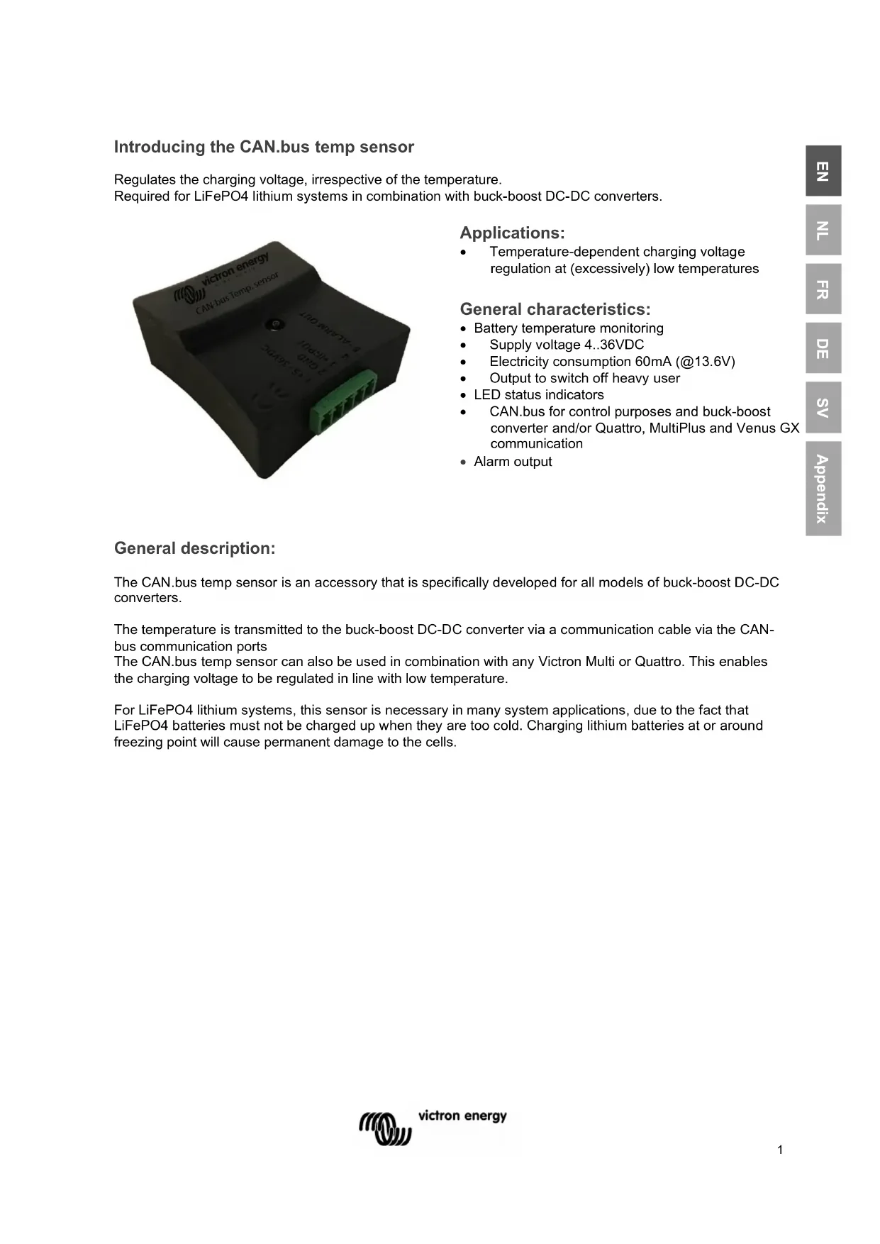
Regulates the charging voltage, irrespective of the temperature.
Required for LiFePO4 lithium systems in combination with buck-boost DC-DC converters.

text_image
victron energy CAN-bus Temp.sensor 1.5 - Alarm Out 3.7 - Electr 1.5 - 240VccApplications:
• Temperature-dependent charging voltage regulation at (excessively) low temperatures
General characteristics:
- Battery temperature monitoring
• Supply voltage 4..36VDC
• Electricity consumption 60mA (@13.6V)
• Output to switch off heavy user
• LED status indicators
• CAN.bus for control purposes and buck-boost converter and/or Quattro, MultiPlus and Venus GX communication - Alarm output
General description:
The CAN.bus temp sensor is an accessory that is specifically developed for all models of buck-boost DC-DC converters.
The temperature is transmitted to the buck-boost DC-DC converter via a communication cable via the CAN-bus communication ports
The CAN.bus temp sensor can also be used in combination with any Victron Multi or Quattro. This enables the charging voltage to be regulated in line with low temperature.
For LiFePO4 lithium systems, this sensor is necessary in many system applications, due to the fact that LiFePO4 batteries must not be charged up when they are too cold. Charging lithium batteries at or around freezing point will cause permanent damage to the cells.
Warnings
Read this manual carefully before installing and commissioning the equipment.
Store the manual carefully and pass it on to a new user of this product!
Explanation of the symbols used

DANGER!
Safety instruction:
Failure to comply will result in death or serious injury.

WARNING!
Safety instruction:
Failure to comply may result in death or serious injury.

CAUTION!
Failure to do so may result in property damage and limit the
functionality of the product.

INSTRUCTION
Additional information for operating the product.
General safety instructions
The manufacturer cannot be held liable for damage in the following cases:
- mounting or connection errors
- product damage by mechanical impacts and overvoltage
- modifications of the product without the express permission of the manufacturer
- use with purposes other than those described in the manual
For safety reasons when installing and using electrical appliances, always observe the risks of electric shock, fire risk and injury!
General safety
 | DANGER!Use a fire extinguisher suitable for electrical appliances in the event of a fire. Always have a fire extinguisher at hand in the premises and use it appropriately. |
 | WARNING!Use the equipment only according to the instructions.Make sure that the plus (+) and minus (-) poles never touch each other.Disconnect the product from the battery when:– performing cleaning and maintenance– replacing a fuse (only by specialists)for disassembly of the product:– Disconnect all connections.– Ensure that all inputs and outputs are energized.If the product or connecting cable is visibly damaged, the product should not be put into operation.If the connection cable of this product is damaged, it must be replaced by a qualified personnel.Repairs to this product may only be performed by the manufacturer. Improper repairs can lead to considerable hazards.This product must not be used by children and by persons with reduced physical, sensory or mental abilities or lacking necessary experience and knowledge. Users should have insight into the dangers that the use of the product entails.Electrical appliances are not toys. Store and use the product for this reason out of reach of children, and ensure that children do not play with the product. |
 | CAUTION!Before commissioning, ensure that the set voltage of the product corresponds to the system voltage of the existing energy supply.Pay attention that other objects cannot cause a short circuit at the contacts of the device.Store the product in a dry and cool place. |
Safety when assembling the product
 | DANGER!Do not mount the product in places where there is a risk of a gas or dust explosion. |
 | WARNING!Provide a stable mounting!The product must be securely mounted and attached to prevent it falling, dropping, and preventing contact of the connections with surrounding objects. |
 | CAUTION!Do not expose the product to heat sources (solar radiation, heating, etc.).Avoid additional heating of the product.Install the product in a dry place protected against splashing water. |
Safety at the electrical connection of the product
 | DANGER!Risk of fatal electric shock!When working on the electrical system, make sure that someone is around who can help in case of an emergency.When installing on boats: Improper installation of electrical appliances on boats can cause corrosion damage to the boat. Have the product connected by a qualified electrician. |
 | WARNING!Provide a sufficient cable intersection.Mount the cables so that they cannot be damaged by doors or hoods. Crushed cables can lead to life-threatening situations, and should be replaced.Install the cables in such a manner that they cannot be tripped over, and any damage to cables is excluded. |
 | CAUTION!Use wire conduits if cables are to be routed through sheet walls or other feedthroughs with sharp edges.Do not combine an AC cable and DC cable in the same channel (wire conduit).Do not loosen the conduits or sharply kink them.Attach the cables with the right materials and tools.Never pull the cables, take sufficiently long cable lengths of sufficient intersection in relation to its length. |
Safe use of the product
 | WARNING!If the product is used in environments with lead-acid batteries, the room should be well ventilated. Explosive hydrogen gas is released from these batteries, which can be ignited by electric sparks.CAUTION!Do not use the appliance– in a salt-containing, damp or wet conditions– nearby aggressive vapours– near flammable materials– in explosive environmentsBefore use, check that the cables and connections are dry.Always disconnect the power supply when working on the product.Parts of the product may still be energized after the product has been disconnected.Do not disconnect cables when the product is still in use. |
 | CAUTION!Prevent the product from being covered or being installed in a space that is too small.Provide proper ventilation. |
Safety when handling batteries
 | WARNING!Batteries may contain harsh and corrosive acids. Avoid any and all physical contact with the battery fluid. In case of skin contact with battery fluids, wash the affected areas of the skin with water.In case of injuries due to acids, please be sure to consult a physician.CAUTION!When working with batteries do not wear metal objects such as watches or rings.Lead-acid batteries can cause short-circuit currents that can lead to serious burns.Risk of explosion!Wear protective goggles and safety clothing when working on batteries. When working with batteries, do not touch your eyes.Do not smoke and make sure there are no sparks nearby the engine or the battery.Do not attempt to charge frozen or defective batteries. In this case, place the battery in a frost-free room and wait until the battery is at ambient temperature. Then start the loading procedure. |
 | CAUTION!Use only rechargeable batteries.Use sufficient cable intersections.Secure the positive cable with a fuse.Prevent metal parts from falling on the battery. This may result in sparks or short-circuiting of the battery and other electrical parts.Pay attention to the correct polarity when connecting.Please observe the battery and equipment manufacturers' instructions listed in corresponding manuals.In case the battery needs to be removed, always disconnect the ground connection first. Then disconnect all other connections and disconnect all consuming points from the battery before removing it. |
Connection

text_image
CAN Bus connector for setting the temperature threshold using TSConfig software LED red/green 5-pin connector Pin 1Connections on 5-pin connector
Pin 1 + 12/24V feed (Note: do not use pin 1 at the same time as the CAN-bus cable!!!)
Pin 2 GND/Min/Earth
Pin 3 + input (no function)
Pin 4 (no function)
Pin 5 - switched output to earth/GND, active in the event of a temperature alarm
| LED indicators | ||
| LED colour | LED indication | Status indication |
| Green | Green 1 sec, thereafter red | Starting up |
| Green LED flashes 1x every 4 seconds | The temperature is above the threshold value set | |
| Green LED flashes 3x | The CAN-bus temp sensor has received a new threshold value from the 800/1600 | |
| Red / Green | A short red flash, followed by 3x green | CAN bus connection |
| Red | A long red flash (1 second) | Stand-alone Mode, no CAN Bus connection |
| Red LED flashes 3x every 4 seconds | The CAN-bus temp sensor (still) does not have a valid threshold value | |
| Red LED lights up for 1 second | The temperature has reached the set threshold value (alarm status active) | |
| Red LED flashes 1x every 4 seconds | The temperature has reached the set threshold value | |
| Technical specification | |
| Dimensions | 57.6 x 40 x 15.8 mm (LxWxH) (incl. connectors) |
| Weight | 12 grams |
| Supply voltage | 4..36VDC |
| Electricity consumption | 60 mA (@13.6V) |
| Alarm output (pin 5) | 350 mA Open connector (switches to GND/Earth) |
Installation
Important!
Basic settings
When using the device for the first time, the following basic settings must be applied:
Programming the threshold value
- Connect the CAN-bus temp sensor to an 800C/1600 using the CAN-bus cable
- Tick checkbox 80 and enter the desired parameters
- Click on "Send all settings to converter"
- No more than 4 seconds later, the green LED on the CAN-bus temp sensor will flash 3 times to confirm
80

CAN bus external temperature sensor
Maximum output current: 5 A when T <= 0 °C
Converter is switched off when T <= -5 °C
After starting up the 800C/1600 or after a reset, it will take no more than 4 seconds before the CAN-bus temp sensor sends a CAN message to the converter. Until a message has been received, the words "no signal" may be displayed in the TSConfig monitor window.
If the connection to the CAN-bus temp sensor is lost (due to a cable break), the 800C/1600 will indicate "no signal" no more than 12 seconds afterwards. If this happens, the temperature threshold programmed in on the 800C/1600 will not be used to limit the charging voltage.
Monitor
1 Input voltage:
13.7 V
3 Output voltage:
6.5 V
4 Output current:
0 A
5 Temperature pcb:
23
CAN temperature sensor:
no signal °C
Setting the CAN-bus temp sensor as a stand-alone module
If the CAN-bus temp sensor is being used as a stand-alone module, a temperature (alarm) threshold value must be programmed first of all.
Programming a threshold value can only be carried out using an 800C/1600 and TSConfig Software.
Alarm
If the temperature has reached the threshold value (= converter off), the converter will be switched off (switching on will be blocked).
The block will not be lifted until the temperature has risen above the alarm threshold for a period of 5 minutes.
text_image
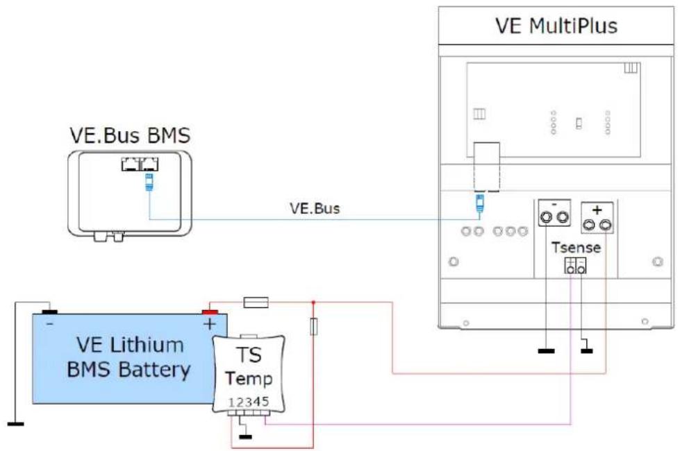
VE.Bus BMS VE.Lithium BMS Battery TS Temp 12345 VE.Bus VE MultiPlus TsenseCAN-bus temp sensor with a Quattro or MultiPlus and a Victron Lithium BMS battery MultiPlus charge current control if the temperature is too low
text_image
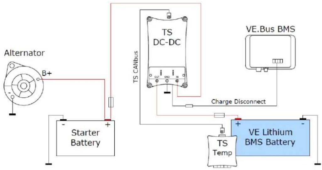
Alternator B+ Starter Battery TS CANbus TS DC-DC Charge Disconnect VE.Bus BMS TS Temp VE Lithium BMS BatteryCAN-bus temp sensor with a buck-boost converter and a Victron Lithium BMS battery Buck-boost converter charging voltage regulator if the temperature is too low
CAN bus external temperature sensor
Maximum output current: 5 A when T <= 0 °C
Converter is switched off when T <= -5 °C
CAN temperature sensor:
no signal °C
CAN-bus Temp sensor instellen als stand-alone module
text_image
VICRON ENERGY CAN-bus Temp. sensor S-ALARM OUT S-ALARM OUT GND +5.2VDCApplications :
CAN bus external temperature sensor
Maximum output current: 5 A when T <= 0 °C
Converter is switched off when T <= -5 °C
CAN temperature sensor:
no signal °C
CAN bus external temperature sensor
Maximum output current: 5 A when T <= 0 °C
Converter is switched off when T <= -5 °C
CAN temperature sensor:
no signal °C
CAN bus external temperature sensor
Maximum output current: 5 A when T <= 0 °C
Converter is switched off when T <= -5 °C
CAN temperature sensor:
no signal °C
Date : January 24 ^th , 2020
Victron Energy B.V.
De Paal 35 | 1351 JG Almere
PO Box 50016 | 1305 AA Almere | The Netherlands
General phone : +31 (0)36 535 97 00
E-mail : sales@victronenergy.com