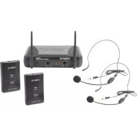
STWM712H - Microphone Vonyx - Free user manual and instructions
Find the device manual for free STWM712H Vonyx in PDF.



| Product type | Wireless VHF HF microphone system |
| Brand | Vonyx |
| Model | STWM712H |
| Reference number | 179.178 |
| Number of channels | 2 |
| Frequency range | 200.175 - 201.400 MHz |
| Frequency stability | <0.005% |
| Maximum deviation | 15 kHz |
| Frequency response | 40 Hz - 20 kHz |
| Signal-to-noise ratio | >100 dB |
| Audio dynamic range | >100 dB |
| Total harmonic distortion (THD) | <0.5% |
| Class | 2 |
| Receiver power supply | Mains 220-240 V AC 50 Hz, adapter 13-15 V DC 500 mA |
| Transmitter power supply | 2 AA 1.5 V batteries (not included) |
| Receiver dimensions | 210 x 145 x 42 mm |
| Pocket transmitter dimensions | 100 x 65 x 30 mm |
| Handheld microphone dimensions | 238 x 50 x 50 mm |
| Antenna | 2 adjustable antennas at 45° |
| Audio outputs | Balanced (XLR) and mixed |
| Operating temperature | 5°C to 35°C |
| Cleaning | Dry cloth only, no chemicals |
| Safety | Do not open the housing; avoid moisture; indoor use only |
Frequently Asked Questions - STWM712H Vonyx
User questions about STWM712H Vonyx
0 question about this device. Answer the ones you know or ask your own.
Ask a new question about this device
Download the instructions for your Microphone in PDF format for free! Find your manual STWM712H - Vonyx and take your electronic device back in hand. On this page are published all the documents necessary for the use of your device. STWM712H by Vonyx.
USER MANUAL STWM712H Vonyx
natural_image
Product photo of a VONYX wireless microphone receiver with external antennas and a handheld microphone (no visible text or symbols on main components)INSTRUCTION MANUAL GEBRUIKSAANWIJZING GEBRAUCHSANLEITUNG MANUAL DE INSTRUCCIONES MANUEL D'INSTRUCTIONS
V1.0
ENGLISH
Congratulations to the purchase of this Vonyx product. Please read this manual thoroughly prior to using the product in order to benefit fully from all features.
Read the manual prior to using the product. Follow the instructions in order not to invalidate the warranty. Take all precautions to avoid fire and/or electrical shock. Repairs must only be carried out by a qualified technician in order to avoid electrical shock. Keep the manual for future reference.
- Prior to using the product, please ask advice from a specialist. When the product is switched on for the first time, some smell may occur. This is normal and will disappear after a while.
- The product contains voltage carrying parts. Therefore do NOT open the housing.
- Do not place metal objects or pour liquids into the product. This may cause electrical shock and malfunction.
- Do not place the product near heat sources such as radiators, etc. Do not place the product on a vibrating surface. Do not cover the ventilation holes.
- The product is not suitable for continuous use.
- Be careful with the mains lead and do not damage it. A faulty or damaged mains lead can cause electrical shock and malfunction.
- When unplugging the product from a mains outlet, always pull the plug, never the lead.
- Do not plug or unplug the product with wet hands.
- If the plug and/or the mains lead are damaged, they need to be replaced by a qualified technician.
- If the product is damaged to such an extent that internal parts are visible, do NOT plug the product into a mains outlet and DO NOT switch the unit on. Contact your dealer. Do NOT connect the product to a rheostat or dimmer.
- To avoid fire and shock hazard, do not expose the product to rain and moisture.
- All repairs should be carried out by a qualified technician only.
- Connect the product to an earthed mains outlet (220-240Vac/50Hz) protected by a 10-16A fuse.
- During a thunderstorm or if the product will not be used for a longer period of time, unplug it from the mains. The rule is: Unplug it from the mains when not in use.
- If the product has not been used for a longer period of time, condensation may occur. Let the unit reach room temperature before you switch it on. Never use the product in humid rooms or outdoors.
-
To prevent accidents in companies, you must follow the applicable guide lines and follow the instructions.
-
Do not repeatedly switch the product on and off. This shortens the life time.
- Keep the product out of the reach of children. Do not leave the product unattended.
- Do not use cleaning sprays to clean switches. The residues of these sprays cause deposits of dust and grease. In case of malfunction, always seek advice from a specialist.
- Do not force the controls.
- If this product is with speaker inside which can cause magnetic field. Keep the product at least 60cm away from computer or TV.
- If the product has built-in lead-acid rechargeable battery. Please recharge the battery every 3 months if you are not going to use the unit for a long period of time. Or the battery may be damaged.
- If the battery is damaged please replace with same specifications battery. And dispose the damaged battery environment friendly.
- If the product has fallen, always have it checked by a qualified technician before you switch the product on again.
- Do not use chemicals to clean the unit. They damage the varnish. Only clean the product with a dry cloth.
- Keep away from electronic equipment that may cause interference.
- Only use original spares for repairs, otherwise serious damage and/or dangerous radiation may occur.
- Switch the product off prior to unplugging it from the mains and/or other equipment. Unplug all leads and cables prior to moving the product.
- Make sure that the mains lead cannot be damaged when people walk on it. Check the mains lead before every use for damages and faults!
- The mains voltage is 220-240Vac/50Hz. Check if power outlet match. If you travel, make sure that the mains voltage of the country is suitable for this product.
- Keep the original packing material so that you can transport the product in safe conditions.

This mark attracts the attention of the user to high voltages that are present inside the housing and that are of sufficient magnitude to cause a shock hazard.

This mark attracts the attention of the user to important instructions that are contained in the manual and that he should read and adhere to.
The product has been certified CE. It is prohibited to make any changes to the product. They would invalidate the CE certificate and their guarantee!
NOTE: To make sure that the product will function normally, it must be used in rooms with a temperature between 5°C/41°F and 35°C/95°F.

Electric products must not be put into household waste. Please bring them to a recycling centre. Ask your local authorities or your dealer about the way to proceed. The specifications are typical. The actual values can slightly change from one unit to the other. Specifications can be changed without prior notice.
Do not attempt to make any repairs yourself. This would invalid your warranty. Do not make any changes to the product. This would also invalid your warranty. The warranty is not applicable in case of accidents or damages caused by inappropriate use or disrespect of the warnings contained in this manual. Vonyx cannot be held responsible for personal injuries caused by a disrespect of the safety recommendations and warnings. This is also applicable to all damages in whatever form.
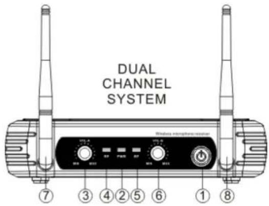
FRONT- AND BACKPANEL
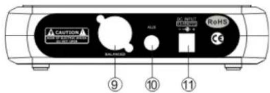
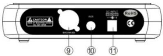
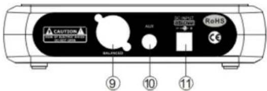
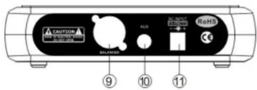
REAR PANEL
- Power switch
- Power signal lamp
- Channel A volume control (not available by 179.185 and 179.187)
- Channel A signal lamp (not available by 179.185 and 179.187)
- Channel B signal lamp
- Channel B volume control
- Channel A antenna
- Channel B antenna
- AF out
- AF mixing out
Models:
179.178 : STWM712H VHF Microphone System 2 channel Headset microphone
179.180: STWM712C VHF Microphone System 2 channel combi (handheld and bodypack)
179.183:STWM712 VHF Microphone System 2 channel handheld microphone
179.185:STWM711 VHF Microphone System 1 channel handheld microphone
179.187: STWM711H VHF Microphone System 1 channel Headset
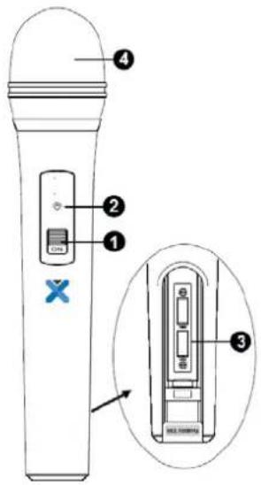
HANDHELD

- Power ON/OFF Switch.
- Low battery indicator: Red light glows when the power is low and change the battery.
- Battery Cover: Open it to install the battery. remove batteries in case of long time no use (prevent leakage).
- Grille: Protects the cartridge and help reducing the breath sounds and wind noise.
BODYPACK
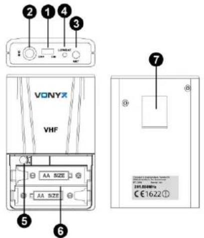
- Power ON/OFF and Audio mute switch.
- Microphone input Jack for headset.
- Antenna
- Low battery indicator (Red light glows when the power is low and change the battery)
- Gain Adjusting Volume: Adjust the transmitter audio input gain.
- Battery Cover: Open it to install the battery. Remove batteries in case of long time no use (prevent leakage).
- Belt Clip
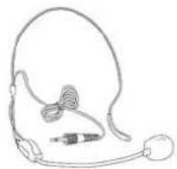
HEADSET MICROPHONE
Connect the connector of supplied headset microphone to the connecting jack of transmitter (Shown as below). Set the transmitter work state in wireless headset system (6).
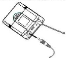
natural_image
Line drawing of a handheld electronic device with a cable and connector (no text or symbols)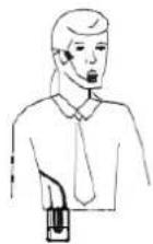
SYSTEM CONNECTIONS
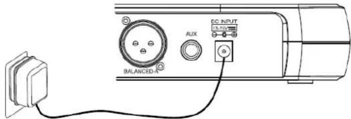
- Receiver power connection: Connect the AC adapter into the DC power connector on the back of the receiver. Plug the AC adapter into a AC230V 50Hz outlet.
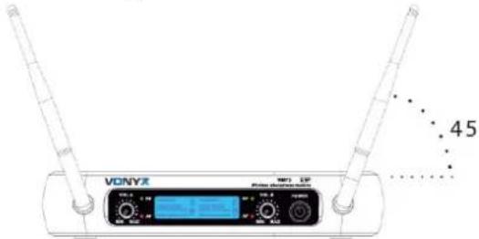
- Antenna: Keep the position of antenna at a 45^ angle from vertical. Shown as below.
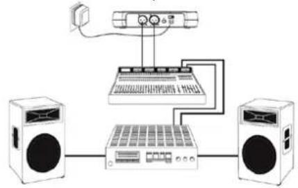
- Audio connection: Connect the audio cable from the audio output on the receiver to the input on your amplifier equipment.
flowchart
graph TD
    A["Speaker 1"] --> B["Audio System"]
    C["Speaker 2"] --> B
    B --> D["Audio Output Unit"]
    D --> E["Switch"]
    E --> B
    B --> F["Audio Record"]
    F --> G["Audio Record"]
    G --> H["Audio Record"]
OPERATION
Turn off the system first, turn down the receivers volume to the minimum and then turn on the receiver, CPU initializes, the LCD screen begins to display and the system reverts to the last shutdown's state!
If the system is turned on look at the transmitter and receiver's frequency. Then the receiver display shows RF signal level value, the antenna status will display antenna A or B. Adjust the volume to the desired level.
Volume adjustment
Adjust the receiver's volume to the 12 o'clock position, then adjust the volume of the amplifier or mixer to a desired level. If the receiver volume has been adjusted too loud the amplifier will produce a saturated distortion which will blow the amplifier or/and the loudspeaker(s)!
Best acoustics:
- You should always see the receiver antenna from your transmitter location.
- The distance between transmitter and receiver should be as short as possible.
- If the receiver has two antennas, they should be adjusted 45^ with a vertical line.
- Keep the antennas away from metal surfaces and shelter.
- Let the antennas not contact or cross each other.
- Before using the system during the presence of public do a test to find out where the "dead spots" are. Avoid these spots when operational
TROUBLESHOOTING
| PROBLEM | INDICATOR | SOLUTION |
| No sound | Red transmitter indicator is not flash | Slide transmitter POWER ON/OFF switch to ON position. Make sure battery is inserted properly, observing battery (+ / -). If battery is inserted properly, replace with fresh battery. |
| No sound | Red transmitter indicator is flash. | Slide transmitter MUTE/ON switch to ON position. |
| No sound | Red receiver indicator POWER light off. | Make sure AC adapter is securely plugged into electrical outlet and into DC input connector.Make sure AC electrical outlet works and supplies proper voltage. |
| No sound | Receiver signal indicators A/B lights glowing. | Turn up receiver volume control. Confirm that the output connections from the receiver to the external equipment are secure. |
| Sound level differs from level of a cabled instrument. | Receiver signal indicators A/B lights glowing. | Adjust transmitter gain level to compessary.Adjust receiver volume as necessary. |
| Distortion level increases gradually | Receiver signal indicators A/B lights and transmitter LOW BATTERY light glowing | Replace transmitter battery |
| Bursts of noise or other audible radio signals present. | Signal indicators A/B/ lights on. | Identify potential sources of interferences (other RF-sources) and turn off, remove or use a wireless system operating on a different frequency. |
| Momentary loss of sound as transmitter is moved around performing area. | Receiver signal indicator A/B lights of when sound is lost | Reposition receiver and perform walk-through test again. If audio dropouts persist, mark “dead” spots and avoid them during performance. |
NEDERLANDS
ACHTERZIJDE
natural_image
Line drawing of a handheld electronic device with cable and connector (no text or symbols)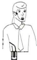
SYSTEEM AANSLUITEN
RÜCKSEITE
natural_image
Line drawing of a handheld electronic device with cable and connector (no text or symbols)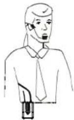
SYSTEMANSCHLÜSSE
flowchart
graph TD
    A["Speaker with sound waves"] --> B["Audio device"]
    B --> C["Computer interface with audio output"]
    C --> D["Speaker with sound waves"]
    D --> E["Audio device"]
    E --> F["Speaker with sound waves"]
BEDIENUNG:
REAR PANEL
179.178 : STWM712H VHF Microphone System 2 channel Headset microphone
179.180 : STWM712C VHF Microphone System 2 channel combi (handheld and bodypack)
179.183: STWM712 VHF Microphone System 2 channel handheld microphone
179.185: STWM711 VHF Microphone System 1 channel handheld microphone
179.187: STWM711H VHF Microphone System 1 channel Headset
MICRÓFONO DE MANO
natural_image
Line drawing of a handheld electronic device with a cable inserted (no text or symbols)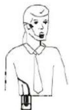
CONEXIONES
natural_image
Line drawing of a medical device with ear and connector (no text or symbols)MICROPHONE SERRE-TETE
natural_image
Line drawing of a handheld electronic device with a cable and connector (no text or symbols)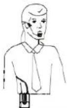
BRANCHEMENTS
A license to operate this equipment may be required in certain areas. Consult your national authority for possible requirements. Licensing of wireless microphone equipment is the user's responsibility and licensability depends on the user's classification, application and frequency.
NEDERLANDS
Class II product for use in Frequency band 195.000-201.900MHz.
The specifications are typical. The actual values can slightly change from one unit to the other. Specifications can be changed without prior notice.

natural_image
Blue glossy circular icon with a stylized white 't' symbol (no text or numbers)tronios
Sound & Light
CE Declaration of Conformity
Manufacturer: TRONIOS BV
Product Description: STWM Series VHF Wireless Microphone
Trade Name: VONYX
Regulatory Requirement: EN 60065 :2002+A2:2010
EN 55013 :2001+A2 :2006 Receiver
EN 55020 :2007 Receiver
EN 301489-1 :2008-04
EN 301489-9 :2007-11
EN 300422-1 :2008-03
EN 300422-2 :2008-03
EN 62479 :2010
I hereby declare that the product meets the requirements stated in Directives 2014/35/EU and 2014/30/EU, R&TTE Directive (1999/5/EC) and conforms to the above mentioned Declarations.
Almelo,
08-06-2017
Name : M. Velders
Signature :
Specifications and design are subject to change without prior notice..
www.tronios.com
Copyright © 2017 by TRONIOS the Netherlands


- ENGLISH
- FRONT- AND BACKPANEL
- Models:
- HANDHELD
- BODYPACK
- HEADSET MICROPHONE
- SYSTEM CONNECTIONS
- OPERATION
- Volume adjustment
- Best acoustics:
- NEDERLANDS
- SYSTEEM AANSLUITEN
- SYSTEMANSCHLÜSSE
- BEDIENUNG:
- MICRÓFONO DE MANO
- CONEXIONES
- MICROPHONE SERRE-TETE
- BRANCHEMENTS
- tronios
- Sound & Light
- CE Declaration of Conformity
Brand : Vonyx
Model : STWM712H
Category : Microphone