WC220L - Toilet Vetus - Free user manual and instructions
Find the device manual for free WC220L Vetus in PDF.



Frequently Asked Questions - WC220L Vetus
User questions about WC220L Vetus
0 question about this device. Answer the ones you know or ask your own.
Ask a new question about this device
Download the instructions for your Toilet in PDF format for free! Find your manual WC220L - Vetus and take your electronic device back in hand. On this page are published all the documents necessary for the use of your device. WC220L by Vetus.
USER MANUAL WC220L Vetus
Installation instructions and 8 Operation manual
Electric marine toilets WC2432
Elektrische Bordtoiletec Wc220s
Toilets marine elettriche WC110L
1 Inleiding
Antivries is gifting. Loos antivries nooit in buitenwater.
6 Onderhoud
Stroom 25A 15A 9A 2,8A
42 liter/min @ 120/230 V
Maximale watertemperatuur : 35^
Geluidsniveau 61 dBA
: IP44
The Vetus WC..S(2) and WC..L(2) toilets are marine toilets with an integrated pump system. With correct installation and operation, these toilets function like a normal toilet.

Note!
These Vetus toilets may only be used for pumping and removal of faeces and toilet paper.
These toilet are not suitable for pumping other objects such as cotton wool pads, tampons, sanitary towels, condoms or hair, or for pumping out fluids like oil. This could cause damage!
Always make sure you have a pair of rubber gloves on board.
2 Working
12 V / 24 V: The particular cycle chosen is carried out automatically after operating the appropriate button.
A choice can be made between the 'ECO' cycle of about 10 seconds and the 'NORMAL' cycle that lasts about 20 onds.
120 V / 230 V: When the button on the toilet pot is pressed the cycle is carried out automatically.
This lasts for about 25 seconds.
The cycle consists of:
A flushing phase:
The magnetic valve allows water to run into the toilet for a set time.
A grinding / pumping phase:
The motor drives the knife blades and the pump. The faeces and toilet paper are ground up and pumped away.
- A phase in which the water seal is brought back to the normal level:
The magnetic valve allows water to run into the toilet for a set time. This forms a water seal and prevents smells in the toilet pot.
3 Safety
Ensure that the power supply is switched off during maintenance or repairs.
4 Installation
4.1 Algemeen
See Page 26 for installation examples.
Always install the toilet in accordance with the applicable regulations of the country concerned. In some areas, it may not be permitted to pump waste straight from the toilet into the water!
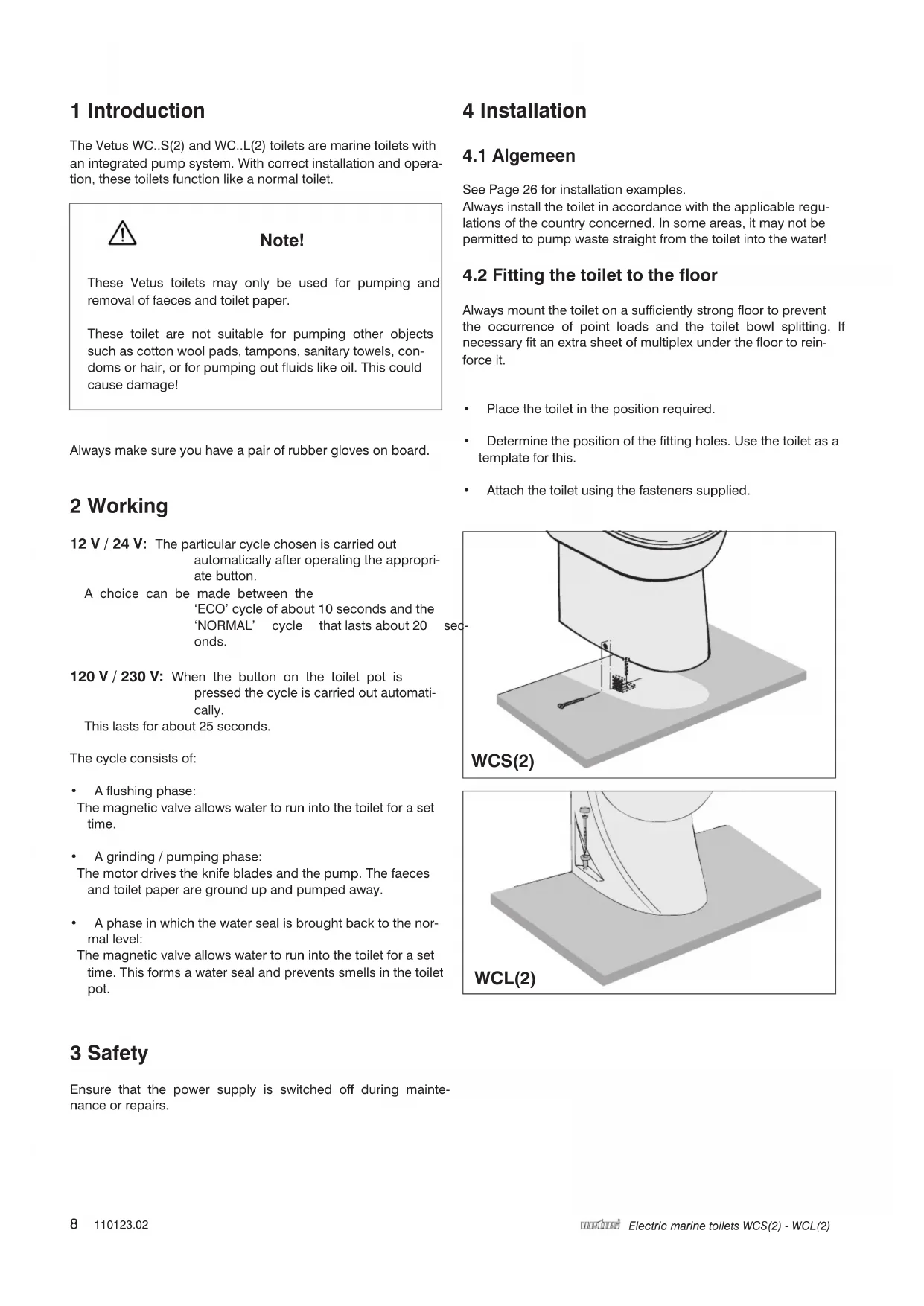
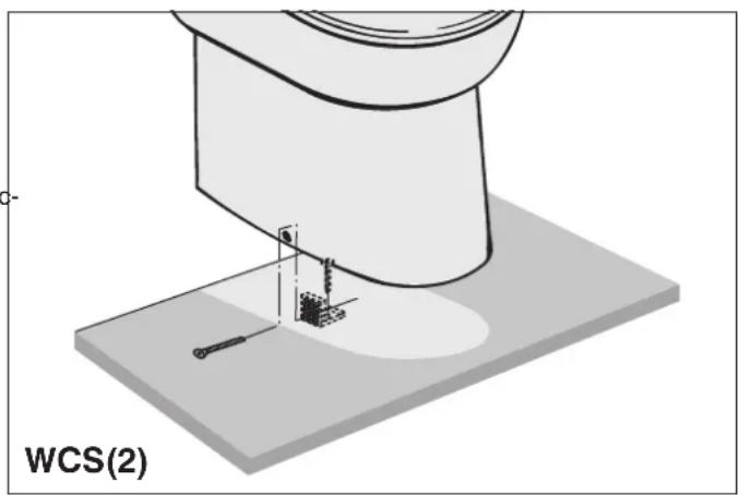
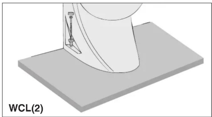
4.2 Fitting the toilet to the floor
Always mount the toilet on a sufficiently strong floor to prevent the occurrence of point loads and the toilet bowl splitting. If necessary fit an extra sheet of multiplex under the floor to reinforce it.
- Place the toilet in the position required.
- Determine the position of the fitting holes. Use the toilet as a template for this.
- Attach the toilet using the fasteners supplied.
4.3 Connections 12 V / 24 V
4.3.1 Outlet
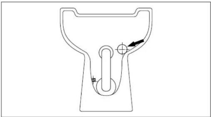
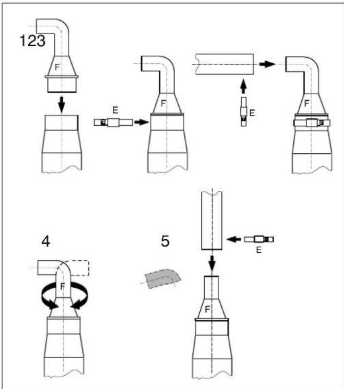
Reducing piece:
- Position the reducing piece (F) in the outlet connection.
Fix the reducing piece using the hose clamp (E). - Fit the outlet hose (Ø 19 mm).
- The reducing piece can be fitted in any position so that the outlet hose can be led to the left, right, up or down as required.
The bent part of the reducing piece can be sawn off in order to lead the outlet behind the toilet.
- For the outlet pipe use a 19mm internal diameter hose (such as the 'Vetus impermeable "no smell" sanitary hose').
- Connect the outlet pipe to a waste water tank or hull access hole with stopcock.
Fix the outlet with clamps.
4.3.2 Water supply
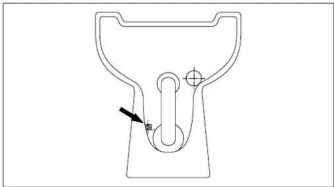
Fit a ball valve with 3 / 4 external connection to the supply pipe and make sure that this will always be accessible.
If there is already a pressurised water system on board the supply hose can be connected to this system. The pressure must be at least 1.5 bar; this is the minimum pressure required to allow the toilet to function properly.
If the water pressure system is less than 1.5 bar or if external water is to be used then a supply pump with capacity of at least 10 litres/minute (2.2 Imp.Gal/min; 2.7 US Gal/min) must be fitted in the water supply pipe.
If external water is to be used then this must be properly filtered.
The toilet has a 3/4" connector.
Connect the flexible water supply hose to the ball valve on the water supply pipe.
4.3.3 Preventing siphoning
When the toilet is below, or less than 40~cm (16") above the waterline, there is a danger of outside water being siphoned into the toilet through the outlet. To prevent this siphoning, fit an air-relief valve in the highest point in the outlet (see Installation examples).
4.4 Connections 120 V / 230 V
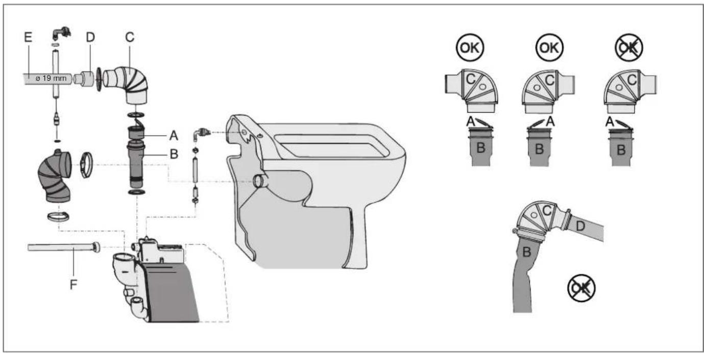
4.4.1 Outlet
- Push the non-return valve (A) into the outlet hose (B).
- Screw in the flexible flap in the right direction (in the direction of flow).
- Fit the elbow piece (C) to the outlet hose clamp supplied.
- Fit the reduction piece (D) to the elbow piece outlet.
- Fit the outlet pipe (E) (19 mm. internal diameter (1")) to the reduction piece using the hose clamp supplied. Use odour-free waste water pipe as outlet pipe.
Take care that the outlet pipe (B) does not kink. - Connect the outlet pipe (E) to a waste water tank or hull access hole with stopcock.
4.4.2 Water supply
The flexible supply pipe (F) has a 3/4 connector.
When a pressurised water system is already installed on board, the supply pipe can be connected to this. However, the pressure in this system should be a minimum of 1.5 Bar (22 psi); this is using mirthumressure for proper flushing.
When the pressure in the water system is less than 1.5 Bar (22 psi), or when water from outside is used as flushing water, then install a water pump in the supply pipe. The capacity of this water supply pump should be minimal 10 litres per minute (2Vetmp.Gal/min; 2.7 US Gal/min).
When water from outside is used for flushing, ensure that this water is very well filtered.
4.4.3 Preventing siphoning
When the toilet is below, or less than 40~cm (16) above the waterline, there is a danger of outside water being siphoned into the toilet through the outlet. To prevent this siphoning, fit an air-relief valve in the highest point in the outlet (see Installation examples).
4.5 Electrical installation 12V / 24V
Check that the voltage given on the type plate on the motor is the same as the voltage on board.
Use batteries with sufficient power to guarantee that the toilet will work correctly.
Connect the power supply as shown in the wiring diagram. Fit a switch and a fuse in the (+^) wire.
Use wires with minimum cross section of 6mm^2 (for 12 V) or 4 mm² (for 24 V).
4.6 Electrical installation 120V / 230V
Check that the voltage given on the type plate on the motor is the same as the voltage on board.
Use batteries with sufficient power to guarantee that the toilet will work correctly.
Connect the power supply as shown in the wiring diagram. Fit a switch and a fuse in the (+^) wire.
Use wires with minimum cross section of 6mm^2 (for 12 V) or 4 mm² (for 24 V).
4.7 Control panel 12V / 24V
Fit the build-in flange with packing in the wall. See the drawing in the section 'Principal dimensions' for the size of the holes. Feed the cable through the flange to the toilet and connect it with the cable on the toilet.
Fit the cover provided over the plug connection for protection. Click the panel into the build-in flange, making sure that the O-ring is fitted properly.
4.8 Testing and preparing for operation
Open the supply pipe stopcock and outlet pipe stopcock fully in order to ensure proper flushing. Press the button, release and check that the cycle operates correctly. Throw a number of pieces of toilet paper in the toilet bowl and flush again.
5 Use
- Make sure that the ball valve in the water support open.
12 V / 24 V: A short or long flush can be used.
-
Short flush (1.2 litres): Press the 'ECO' button.
-
Long flush (2.2 litres): Press the 'NORMAL' ton.

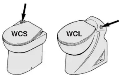
120 V / 230 V: You have the option of a short or a long flush:
- Short flush (1.2 litres): Press the button once.
- Long flush (2.8 litres): Press the button twice. Press the button once for one flush (5 litres).
After using the toilet shut off the ball valve.
If the toilet has not been used for some time it is advisable to rinse it with clean water a few times before using it.
The following precautions must be taken during periods of frost (winter):
- Shut off the water supply to the toilet.
12V/24V:
- Pump the toilet empty by pressing the button with the pump symbol and holding this in.

120 V / 230 V: Carry out a cycle without water.
Pour about 2 litres anti-freeze into the toilet pot.
Drain the pipes.
Anti-freeze is poisonous and must never be drained into the external water.
6 Maintenance
Traditional toilet cleaners can be used to clean the toilet and to remove scale.
In order to prevent scale deposits from building up in the pump these must be removed regularly as follows:
- Shut off the water supply by closing the ball valve.
12 V/24 V: Pump the toilet empty by pressing the button with the pump symbol and holding this in.

120 V / 230 V: Carry out a cycle without water.
- Pour about 1 litre of vinegar or scale remover into the toilet pot and let it soak for some hours.
- Open the ball valve again and carry out several weight cycles in order to flush the toilet pot thoroughly and remove all the water used from the pump.
Protection : IP44
Weight cycles in WCS(2) : 23 Kg (50 lbs) WCL(2) : 29 Kg (64 lbs)
How often the scale needs to be removed depends on the hardness of the water, but it should be done at least twice a year.
Do not use products based on sodium (unblocking products) or solvents.
If seawater is used for flushing the toilet should be rinsed through with fresh water every so often to prevent salt deposits from building up.
7 Technical details
Voltage : 12 V 24 V 110 V 230 V
Current 25A 15A 9A 2.8A
Maximum vertical lift in outlet : 3 metres
Maximum hose length: 30 metres
Pump capacity at discharge height of 3 metres
36 litres/min @ 12 V
43 litres/min @ 24 V
42 litres/min @ 120/230 V
Maximum water
temperature : 35^ C
Noise level 61 dBA
8 Fault Tracing
Ensure that the power supply is switched off during repairs.
| Fault | Possible cause | Solution |
| The motor runs and the cycle operates correctly, But the water is pumped out very slowly, or not at all. | · The air-relief valve does not shut properly. | · Clean the air-relief valve, or replace it. |
| · The outlet pipe is blocked. | · Descale the outlet pipe. | |
| 12 V / 24 V | · The pump housing is blocked. | · Clean the pump housing. |
| 120 V / 230 V | · The sieve is blocked. | · Clean the sieve. |
| The cycle runs properly but a small amount of water remains in the bowl. | · The discharge height is too great. | · Modify the installation. |
| · The outlet pipe iis blocked. | · Descale the outlet. | |
| The motor makes a rattling noise. | · Hard object in sieve hitting the revolving blades. | · Take motor block apart and object from sieve. |
| Cycle does not run after the button is pressed. | · There is no power | · Check the main switch and fuse |
| · The plug connection to the panel is loose | · Replace the control electronics | |
| · There is a fault in the control electronics | · Press button firmly. | |
| · The button has not been pressed hard enough. | · Free the transparent hose. | |
| · The transparent hose from the button is jammed so that the pressure switch is not operated. | · Replace the pressure switch. | |
| · The pressure switch is faulty. | · Replace timer. | |
| · The timer is faulty. | · Clean the filter. | |
| The cycle starts but water flows too slowly into the bowl. | · The magnetic valve filter is blocked. | · Ensure minimum water pressure is 1.5 bar (24 psi). |
| · Water pressure too low. | ||
| Cycle starts but no water flows into the bowl. | · The water supply stopcock is off. | turnon the stopcock. |
| · Faulty magnetic valve. | · Replace magnetic valve. | |
| · Water pressure too low. | · Ensure a minimum water pressure of 1.5 Bar (24 psi). |
1 Einführung
4.3 Anschlüsse 12 V / 24 V
4.3.1 Ablass
Reduzierstück:
42 Liter/min @ 120/230 V
Maximale Wassertemp.: 35^ C
Schallpegel 61 dBA
Sicherung : IP44
Gewicht WCS(2) : 23 kg
WCL(2) : 29 kg
8 Störungen
4.3 Raccordements 12 V / 24 V
4.3.1 Evacuation
43 litros/min @ 24 V
42litros/min @ 120/230 V
Maxima temperatura
delagua 35°C
Nivel sonoro 61 dBA
Protection
IP44
Examples d-installation
Watertoevoer Water supply
1 Pump
2 Filter
3 Ball valve
4 Air valve
5 Water tank
6 Dirty water tank
1Pumpe
2 Filter
3 Kugelhahn
4 Entlufter
5 Wassertank
6 Schwarzwassertank
Principal dimensions
Hauptabmessungen
Dimensions principales
This product complies to the requirements of EC Directive:
Printed in the Netherlands
110123.02 09-08