NEC3120FW - Tumble drier AMANA - Free user manual and instructions
Find the device manual for free NEC3120FW AMANA in PDF.
Frequently Asked Questions - NEC3120FW AMANA
User questions about NEC3120FW AMANA
0 question about this device. Answer the ones you know or ask your own.
Ask a new question about this device
Download the instructions for your Tumble drier in PDF format for free! Find your manual NEC3120FW - AMANA and take your electronic device back in hand. On this page are published all the documents necessary for the use of your device. NEC3120FW by AMANA.
USER MANUAL NEC3120FW AMANA
Your safety and the safety of others are very important.
We have provided many important safety messages in this manual and on your appliance. Always read and obey all safety messages.

This is the safety alert symbol.
This symbol alerts you to potential hazards that can kill or hurt you and others.
All safety messages will follow the safety alert symbol and either the word "DANGER" or
"WARNING." These words mean:
! DANGER
You can be killed or seriously injured if you don't immediately follow instructions.
WARNING
You can be killed or seriously injured if you don't follow instructions.
All safety messages will tell you what the potential hazard is, tell you how to reduce the chance of injury, and tell you what can happen if the instructions are not followed.

WARNING - "Risk of Fire"
- Clothes dryer installation must be performed by a qualified installer.
- Install the clothes dryer according to the manufacturer's instructions and local codes.
- Do not install a clothes dryer with flexible plastic venting materials or flexible metal (foil type) duct. If flexible metal duct is installed, it must be of a specific type identified by the appliance manufacturer as suitable for use with clothes dryers. Flexible venting materials are known to collapse, be easily crushed, and trap lint. These conditions will obstruct clothes dryer airflow and increase the risk of fire.
- To reduce the risk of severe injury or death, follow all installation instructions.
- Save these instructions.
IMPORTANT SAFETY INSTRUCTIONS
When discarding or storing your old clothes dryer, remove the door.
SAVE THESE INSTRUCTIONS
IMPORTANT SAFETY INSTRUCTIONS
WARNING: To reduce the risk of fire, electric shock, or injury to persons when using the dryer, follow basic precautions, including the following:
- Read all instructions before using the dryer.
■ Do not place items exposed to cooking oils in your dryer. Items contaminated with cooking oils may contribute to a chemical reaction that could cause a load to catch fire. - Do not dry articles that have been previously cleaned in, washed in, soaked in, or spotted with gasoline, dry-cleaning solvents, or other flammable or explosive substances as they give off vapors that could ignite or explode.
■ Do not allow children to play on or in the dryer. Close supervision of children is necessary when the dryer is used near children.
■ Before the dryer is removed from service or discarded, remove the door to the drying compartment.
■ Do not reach into the dryer if the drum is moving.
■ Do not install or store the dryer where it will be exposed to the weather.
■ Do not tamper with controls.
■ Do not repair or replace any part of the dryer or attempt any servicing unless specifically recommended in this Use and Care Guide or in published user-repair instructions that you understand and have the skills to carry out.
■ Do not use fabric softeners or products to eliminate static unless recommended by the manufacturer of the fabric softener or product.
■ Do not use heat to dry articles containing foam rubber or similarly textured rubber-like materials.
■ Clean lint screen before or after each load.
- Keep area around the exhaust opening and adjacent surrounding areas free from the accumulation of lint, dust, and dirt.
■ The interior of the dryer and exhaust vent should be cleaned periodically by qualified service personnel.
■ See "Electrical Requirements" located in the installation instructions for grounding instructions.
SAVE THESE INSTRUCTIONS
State of California Proposition 65 Warnings:
WARNING: This product contains one or more chemicals known to the State of California to cause cancer.
WARNING: This product contains one or more chemicals known to the State of California to cause birth defects or other reproductive harm.
Installation Instructions
Tools and Parts
Tools needed
Gather the required tools and parts before starting installation. Read and follow the instructions provided with any tools listed here.
natural_image
Simple line drawing of a screwdriver (no text or symbols)
natural_image
Line drawing of a pliers with a handle and metal fastener (no text or symbols)Flat-blade screwdriver Tin snips (new vent installations)
natural_image
Simple diagram with three circular symbols inside a rectangular box (no text or labels)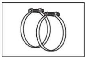
natural_image
Two interlocked rings with metal clips attached (no text or symbols)Level Vent clamps
natural_image
Line drawing of an adjustable wrench (no text or symbols)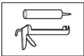
natural_image
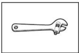
Two hand tools or calipers shown in line drawings (no text or symbols)Adjustable wrench that opens to 1" (25 mm) or hex-head socket wrench
Caulking gun and compound (for installing new exhaust vent)
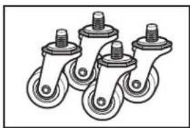
Parts supplied
Remove parts package from the dryer drum. Check that all parts listed are included.
natural_image
Simple geometric diagram with concentric circles and a shaded central region (no text or symbols)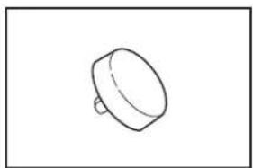
natural_image
Simple line drawing of a cylindrical object with a protruding shaft (no text or symbols)Cycle control knob Start button
natural_image
Illustration of four different types of wheel switches with threaded pins (no text or symbols)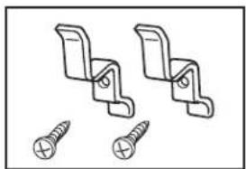
natural_image
Technical line drawing of two bracket fasteners with screw holes (no text or symbols)Casters (4) Cord brackets (2) and
screws (2)
Parts needed
Check local codes, existing electrical supply and venting, and see "Venting Requirements" and "Electrical Requirements" before purchasing parts.
■Mobile home installations require metal exhaust system hardware.
For information on ordering, please refer to "Assistance or Service" on the back cover. You may also contact the dealer from whom you purchased your dryer.
Location Requirements
WARNING
Explosion Hazard
Keep flammable materials and vapors, such as gasoline, away from dryer.
Place dryer at least 18 inches (460 mm) above the floor for a garage installation.
Failure to do so can result in death, explosion, or fire.
You will need
■A location that allows for proper exhaust installation. See "Venting Requirements."
■A 120-volt, 60-Hz., AC only, 15- or 20-amp circuit.
■A grounded electrical outlet located within 2 ft (610 mm) of either side of the dryer. See "Electrical Requirements."
■A sturdy floor to support the dryer weight (dryer and load) of 115 lbs (52 kg). The combined weight of a companion appliance should also be considered.
■A level floor with a maximum slope of 1" (25 mm) under entire dryer.
Do not operate your dryer at temperatures below 45^ F ( 7^ C). At lower temperatures, the dryer might not shut off at the end of an automatic cycle. Drying times can be extended.
The dryer must not be installed or stored in an area where it will be exposed to water and/or weather.
Check code requirements. Some codes limit, or do not permit, installation of the dryer in garages, closets, mobile homes, or sleeping quarters. Contact your local building inspector.
Installation Clearances
The location must be large enough to allow the dryer door to open fully.
Dryer Dimensions
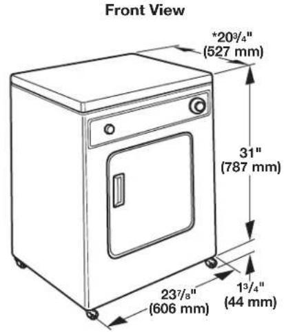
text_image
Front View *20¾" (527 mm) 31" (787 mm) 23¾" (606 mm) 1¾" (44 mm)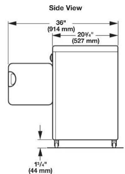
text_image
Side View 36" (914 mm) 20¾" (527 mm) 1¾" (44 mm)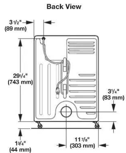
text_image
Back View 3 1/2" (89 mm) 29 1/4" (743 mm) 3 1/4" (83 mm) 1 3/4" (44 mm) 11 7/8" (303 mm)Minimum spacing for recessed area and closet installation
The following dimensions shown are for the minimum spacing allowed when the dryer is to be operated with, or without, the Stack Stand Kit. To purchase a Stack Stand Kit, see "Assistance or Service."
■Additional spacing should be considered for ease of installation and servicing.
■Additional clearances might be required for wall, door, and floor moldings.
■For closet installation with a door, minimum ventilation openings in the top and bottom of the door are required. Louvered doors with equivalent ventilation openings are acceptable.
■Companion appliance spacing should also be considered.
Recessed or closet installation - Dryer only
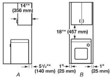
text_image
14" (356 mm) 18"* (457 mm) 5½"* (140 mm) 1" (25 mm) 1" (25 mm) A BA. Side view - closet or confined area
B. Recessed area
*Most installations require a minimum 5½" (140 mm) clearance behind the dryer for the exhaust vent with elbows. See "Venting Requirements."
Recessed or closet installation - Stacked
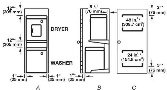
text_image
12" (305 mm) 12" (305 mm) DRYER WASHER 5 1/2" (76 mm) 48 in.2" (309.7 cm²) 24 in.2" (154.8 cm²) 3" (76 mm) 1" (25 mm) 1" (25 mm) 1" (25 mm) A B CA. Recessed area
B. Side view - closet or confined area
C. Closet door with vents
Mobile Home - Additional Location Requirements
This dryer is suitable for mobile home installations. The installation must conform to the Manufactured Home Construction and Safety Standard, Title 24 CFR, Part 3280 (formerly the Federal Standard for Mobile Home Construction and Safety, Title 245, HUD Part 280) or Standard CAN/CSA-Z240 MH.
Mobile home installations require:
■Metal exhaust system hardware, which is available for purchase from your dealer.
■Special provisions must be made in mobile homes to introduce outside air into the dryer. The opening (such as a nearby window) should be at least twice as large as the dryer exhaust opening.
Electrical Requirements
WARNING

Electrical Shock Hazard
Plug into a grounded 3 prong outlet.
Do not remove ground prong.
Do not use an adapter.
Do not use an extension cord.
Failure to follow these instructions can result in death, fire, or electrical shock.
■120 Volt, 60 Hz, AC only, 15- or 20- amp fused electrical supply is required.
■A time-delay fuse or circuit breaker is recommended. Check that the fuse or circuit breaker matches the rating of your line.
■It is also recommended that a separate circuit serving only this dryer be provided.
■Do not use an extension cord.
GROUNDING INSTRUCTIONS
■ For a grounded, cord-connected dryer: This dryer must be grounded. In the event of malfunction or breakdown, grounding will reduce the risk of electric shock by providing a path of least resistance for electric current. This dryer is equipped with a cord having an equipment-grounding conductor and a grounding plug. The plug must be plugged into an appropriate outlet that is properly installed and grounded in accordance with all local codes and ordinances.
WARNING: Improper connection of the equipment-grounding conductor can result in a risk of electric shock. Check with a qualified electrician or service representative or personnel if you are in doubt as to whether the dryer is properly grounded. Do not modify the plug provided with the dryer: if it will not fit the outlet, have a proper outlet installed by a qualified electrician.
SAVE THESE INSTRUCTIONS
Venting
Venting Requirements
WARNING

Fire Hazard
Use a heavy metal vent.
Do not use a plastic vent.
Do not use a metal foil vent.
Failure to follow these instructions can result in death or fire.
WARNING: To reduce the risk of fire, this dryer MUST BE EXHAUSTED OUTDOORS.
IMPORTANT: Observe all governing codes and ordinances.
Dryer exhaust must not be connected into any gas vent, chimney, wall, ceiling, attic, crawlspace, or a concealed space of a building. Only rigid or flexible metal vent shall be used for exhausting.
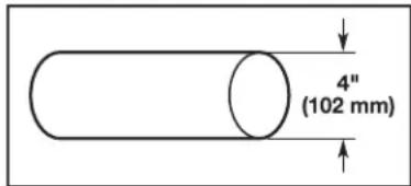
text_image
4" (102 mm)4" (102 mm) heavy metal exhaust vent
■ Only a 4" (102 mm) heavy metal exhaust vent and clamps may be used.
■Do not use plastic or metal foil vent.
Rigid metal vent:
■Recommended for best drying performance and to avoid crushing and kinking.
Flexible metal vent: (Acceptable only if accessible to clean)
■Must be fully extended and supported in final dryer location.
■Remove excess to avoid sagging and kinking that may result in reduced airflow and poor performance.
■Do not install in enclosed walls, ceilings, or floors.
■The total length should not exceed 7 ^3/4 ft. (2.4 m).
NOTE: If using an existing vent system, clean lint from entire length of the system and make sure exhaust hood is not plugged with lint. Replace plastic or metal foil vents with rigid metal or flexible metal vents. Review "Vent System Chart" and, if necessary, modify existing vent system to achieve best drying performance.
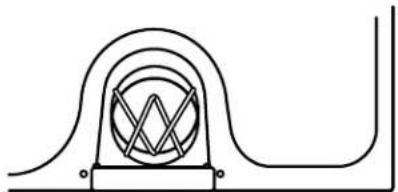
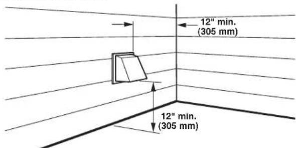
Exhaust hoods:
■ Must be at least 12" (305 mm) from ground or any object that may obstruct exhaust (such as flowers, rocks, bushes, or snow).
Recommended Style:
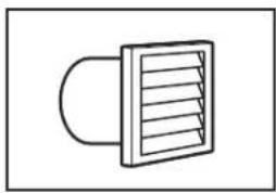
natural_image
Simple line drawing of a vent or airflow device with no text or symbols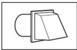
natural_image
Simple line drawing of a mechanical component or bracket (no text or symbols)Louvered hood Box hood
Acceptable Style:
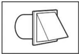
natural_image
Simple line drawing of a mechanical component or bracket (no text or symbols)Angled hood
Elbows
45° elbows provide better airflow than 90° elbows.
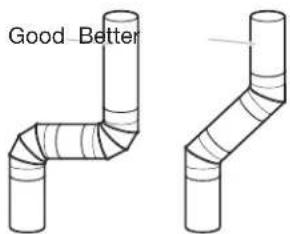
text_image
Good BetterClamps
■Use clamps to seal all joints.
■Exhaust vent must not be connected or secured with screws or other fastening devices that extend into the interior of the duct, because they can catch lint. Do not use duct tape.
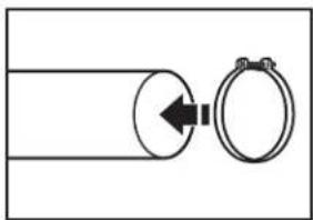
natural_image
Simple line drawing of two circular components connected by a double-headed arrow (no text or symbols)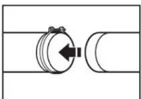
natural_image
Pure mechanical diagram showing a cylindrical component connected to a curved pipe (no text or symbols)Improper venting can cause moisture and lint to collect indoors, which may result in:
■ Moisture damage to woodwork, furniture, paint, wallpaper, carpets, etc.
■ Housecleaning problems and health problems.
Plan Vent System
Choose your exhaust installation type
Recommended exhaust installations:
Typical installations vent the dryer from the rear of the dryer. Other installations are possible.
text_image
A B CA. Exhaust hood
B. Flexible metal or rigid metal vent
C. Elbow
Alternate installations for close clearances:
Venting systems come in many varieties. Select the type best for your installation. Two close-clearance installations are shown. Refer to the manufacturer's instructions.
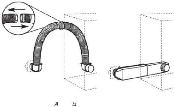
natural_image
Technical illustration of a flexible hose assembly with cross-sectional view (A-B), no text or symbols presentA. Over-the-top installation
(also available with one offset elbow)
B. Periscope installation
NOTE: The following kits for close clearance alternate installations are available for purchase. For information on ordering, see "Assistance or Service."
■Over-the-Top Installation:
Part Number 4396028
■Periscope Installation (for use with dryer vent to wall vent mismatch):
Part Number 4396037 - for mismatch of 0" (0 mm) to 18" (457 mm)
Part Number 4396011 - for mismatch of 18" (457 mm) to 29" (737 mm)
Part Number 4396014 - for mismatch of 29" (737 mm) to 50" (1.27 m)
Special provisions for mobile home installations:
The exhaust vent must be securely fastened to a noncombustible portion of the mobile home structure and must not terminate beneath the mobile home. Terminate the exhaust vent outside.
natural_image
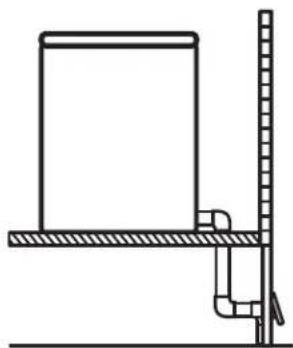
Simple line drawing of a vertical scale measuring a rectangular object on a horizontal surface (no text or symbols)Determine vent path
■Select the route that will provide the straightest and most direct path outdoors.
■Plan the installation to use the fewest number of elbows and turns.
■When using elbows or making turns, allow as much room as possible.
■Bend vent gradually to avoid kinking.
■Use the fewest 90° turns possible.
Determine vent length and elbows needed for best drying performance
■Use the "Vent System Chart" below to determine type of vent material and hood combinations acceptable to use.
NOTE: Do not use vent runs longer than those specified in the Vent system chart. Exhaust systems longer than those specified will:
■Shorten the life of the dryer.
■Reduce performance, resulting in longer drying times and increased energy usage.
The "Vent System Chart" provides venting requirements that will help to achieve the best drying performance.
Vent System Chart
| Number of 90° turns or elbows | Type of vent Box or louvered hoods | Angled hoods |
| 0 | Rigid metal 36 ft (11 m) 26 ft (7.9 m) | |
| 1 | Rigid metal 26 ft (7.9 m) 16 ft (4.9 m) | |
| 2 | Rigid metal 16 ft (4.9 m) 6 ft (1.8 m) |
Install Vent System
- Before installing the vent system, be sure to remove the wire exhaust guard that is located at the exhaust outlet.
natural_image
Pure technical line drawing of a mechanical component with no text or symbols- Install exhaust hood.
text_image
12" min. (305 mm) 12" min. (305 mm)Install exhaust hood and use caulking compound to seal exterior wall opening around exhaust hood.
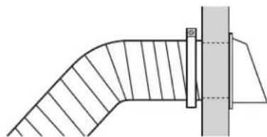
- Connect vent to exhaust hood.
natural_image
Technical line drawing of a curved structural component with hatched fill and a vertical support (no text or symbols)Vent must fit inside exhaust hood. Secure vent to exhaust hood with 4" (102 mm) clamp. Run vent to dryer location. Use the straightest path possible. See "Determine vent path" in "Plan Vent System." Avoid 90° turns. Use clamps to seal all joints. Do not use duct tape, screws, or other fastening devices that extend into the interior of the vent to secure vent, because they can catch lint.
Install Cord Bracket and Casters
Do not move dryer into its final location until the following steps have been performed.
WARNING
Excessive Weight Hazard
Use two or more people to move and install dryer.
Failure to do so can result in back or other injury.
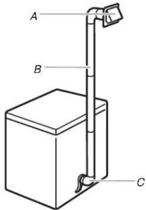
Install cord bracket
-
Remove tape from the power cord and the rear panel.
-
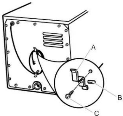
Insert cord brackets into slotted holes in rear panel and secure with screws provided.
text_image
Technical diagram of a device with labeled components A, B, and C, showing internal wiring and a magnified inset view.A. Cord bracket
B. Slotted hole
C.
Screw
NOTE: Power supply cord may be wrapped around the brackets for storage convenience when dryer is not in use.
Install casters
-
To avoid damaging floor, use a large flat piece of cardboard from dryer carton. Place cardboard under entire back edge of the dryer.
-
Firmly grasp dryer body and gently lay dryer on cardboard.
natural_image
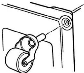
Technical line drawing of a mechanical pulley system with no text or symbols-
Screw casters into dryer base at four corners and tighten securely.
-
Set the dryer upright. In doing so, be certain that the dryer does not roll away from you.
Connect Vent
- Connect vent to exhaust outlet.
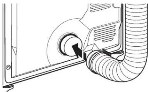
natural_image
Technical line drawing of a mechanical component with hoses and a central hub (no text or symbols)Using a 4" (102 mm) clamp, connect vent to exhaust outlet in dryer. If connecting to existing vent, make sure the vent is clean. Dryer vent must fit over dryer exhaust outlet and inside exhaust hood. Check that vent is secured to exhaust hood with a 4" (102 mm) clamp.
- Move dryer into its final location. Avoid crushing or kinking the vent.
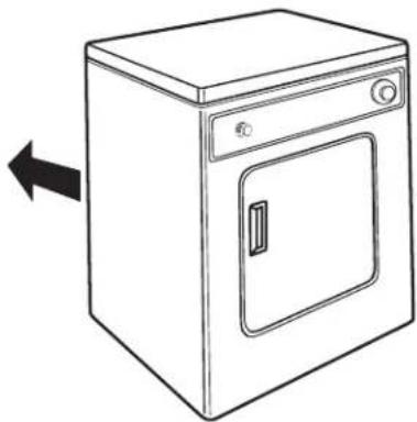
natural_image
Line drawing of a simple kitchen appliance with a door and front panel, shown with an arrow pointing left (no text or symbols)- Once exhaust vent connection is made, remove cardboard.
Complete Installation
-
Check that all parts are now installed. If there is an extra part, go back through the steps to see what was skipped.
-
Check that you have all of your tools.
-
Dispose of/recycle all packaging materials.
-
Check dryer's final location. Be sure vent is not crushed or kinked.
-
Check that dryer is on a level surface.
-
Plug into a grounded 3 prong outlet.
-
Remove film on the console and any tape remaining on dryer. Remove tape from lint screen (located on inside back wall of dryer).
-
Read "Dryer Use."
-
Wipe dryer drum interior thoroughly with a damp cloth to remove any dust.
-
To test the dryer, set the dryer on a full heat cycle (not an air cycle) for 20 minutes and start the dryer.
If the dryer will not start, check the following:
■Controls are set in a running or "On" position.
■Start button has been firmly pressed.
■Dryer is plugged into a grounded 3 prong outlet.
■Household fuse is intact and tight, or circuit breaker has not tripped.
■Dryer door is closed.
- When the dryer has been running for 5 minutes, open the dryer door and feel for heat. If you feel heat, cancel cycle and close the door.
If you do not feel heat, check the following:
■Controls are set on a heated cycle, not an air cycle.
NOTE: You may notice an odor when dryer is first heated. This odor is common when the heating element is first used. The odor will go away.
Using Your Dryer

START
Amana
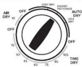
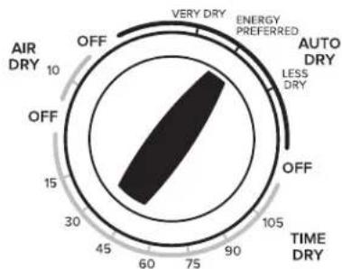
text_image
AIR DRY OFF 10 VERY DRY ENERGY PREPARED AUTO DRY LESS DRY OFF 15 30 45 60 75 90 105 TIME DRYStarting Your Dryer
WARNING
Explosion Hazard
Keep flammable materials and vapors, such as gasoline, away from dryer.
Do not dry anything that has ever had anything flammable on it (even after washing).
Failure to follow these instructions can result in death, explosion, or fire.
WARNING: To reduce the risk of fire, electric shock, or injury to persons, read the IMPORTANT SAFETY INSTRUCTIONS before operating this appliance.
Before using your dryer, wipe the dryer drum with a damp cloth to remove dust from storing and shipping.
- Clean the lint screen before each load. See "Cleaning the Lint Screen."
- Load clothes loosely into the dryer and close the door. Do not pack the dryer. Allow space for clothes to tumble freely.
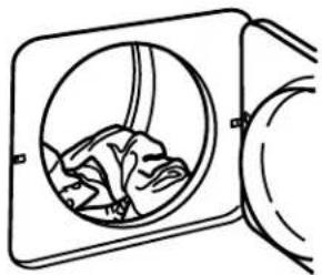
natural_image
Simple line drawing of a window with a fan inside, no text or symbols presentWARNING

Fire Hazard
No washer can completely remove oil.
Do not dry anything that has ever had any type of oil on it (including cooking oils).
Items containing foam, rubber, or plastic must be dried on a clothesline or by using an Air Cycle.
Failure to follow these instructions can result in death or fire.
- Turn the Cycle Control knob to the recommended cycle for the type of load being dried. Use the Perm Press Energy Preferred Automatic Setting to dry most heavyweight and medium weight loads. See "Drying, Cycle, and Temperature Tips."
radar
| Category | Value | |---|---| | AIR DRY | 10 | | OFF | 15 | | TIME DRY | 105 | | OFF | 90 | | VERY DRY | 80 | | ENERGY PREFERRED | 75 | | AUTO DRY | 60 | | LESS DRY | 45 | | 30 | 30 |- Press START.
Stopping and Restarting
You can stop your dryer anytime during a cycle.
To stop your dryer:
Open dryer door or turn Cycle Control knob to OFF.
NOTE: The Cycle Control knob should point to an Off area when dryer is not in use.
To restart your dryer:
- Close the door.
- Select a new cycle and temperature (if desired).
- Press the START button.
Loading
Load clothes loosely into the dryer. Do not overload the dryer. Allow space for clothes to tumble freely. The following chart shows the maximum load you can place in your compact dryer. Expect longer drying times.
| Heavy work clothes | 2 pair of pants, 3 work shirts |
| Delicates | 1 camisole, 2 slips, 4 undergarments, 1 set of sleepwear, 1 half slip |
| Towels | 9 bath towels; or 6 bath towels, 3 hand towels, 6 washcloths |
| Mixed load | 2 pillowcases, 1 T-shirt, 2 shirts, 1 pair slacks |
| Knits | 2 slacks, 2 shirts; or 3 dresses |
| Perm Press | 6 shirts; or 2 double sheets & 2 pillowcases; or 2 singles sheets & 2 pillowcases |
Drying, Cycle, and Temperature Tips
Select the correct cycle and temperature for your load.
Your dryer tumbles the load without heat during the last few minutes of all cycles to make the load easier to handle.
Drying tips
■Follow care label directions when they are available.
■If desired, add a fabric softener sheet. Follow package instructions.
■Remove load from the dryer as soon as tumbling stops to reduce wrinkling. This is especially important for permanent press, knits, and synthetic fabrics.
Cycle and temperature tips
■Dry most loads using the Energy Preferred setting.
■Use a no heat (air) setting for rubber, plastic, or heat-sensitive fabrics.
■Line-dry bonded or laminated fabrics.
NOTE: If you have questions about drying temperatures for various loads, refer to the care label directions.
Cycles
Auto Dry
This automatic cycle shuts off the dryer when the Auto Moisture Sensing feature determines the selected dryness level has been reached. The Cycle Control knob does not move until the load is almost dry. After the cool down, the knob automatically turns to an Off area and tumbling stops.
Dry most loads using the Energy Preferred setting. Drying time with an Auto Dry cycle varies according to the type of fabric, size of load, and temperature setting.
If the load is drier than you like, select a setting closer to Less Dry the next time you dry a similar load.
If the load is not as dry as you like, complete drying using the Time Dry cycle. The next time you dry a similar load, select a setting closer to Very Dry.
How Auto Moisture Sensing Works
With Auto Moisture Sensing, the dryness of the load is determined by two metal strips (sensors) located on the inside of the dryer. The metal strips help detect the amount of moisture left in the clothes as they pass. When there is moisture left in the clothes, the Cycle Control knob will not advance. As clothes begin to dry, the amount of water left in the clothes decreases, and the timer advances through the remainder of the cycle. When the selected dryness level is reached, the dryer goes into a cool down period of up to 5 minutes.
Air Dry
Use this cycle for items that require drying without heat, such as rubber, plastic and heat-sensitive fabrics. See the chart for examples of items that can be dried using an air cycle.
| Type of Load Time* | |
| Foam rubber - pillows, padded bras, stuffed toys | 20 - 30 |
| Plastic - shower curtains, tablecloths | 20 - 30 |
| Rubber-backed rugs 40 - 50 | |
| Olefin, polypropylene, sheer nylon | 10 - 20 |
*(Minutes). Reset cycle to complete drying, if needed.
When using an air cycle
■Check that coverings are securely stitched.
■Shake and fluff pillows by hand periodically during cycle.
■Dry item completely. Foam rubber pillows are slow to dry.
Time Dry Cycle
Use this cycle to complete drying if items are still damp after the automatic cycle.
Time Dry is also useful for:
■Heavyweight items and work clothes that require a long drying time.
■Lightweight items, such as lingerie, blouses and knits that require a short drying time.
For damp dry, turn the Cycle Control knob to 30 minutes or less.
End of Cycle Signal
The dryer sounds a signal to let you know when the cycle is finished. The signal is not adjustable and cannot be turned off. The signal is helpful when you are drying permanent press, synthetics and other items that should be taken out as soon as the dryer stops.
Dryer Care
Cleaning the Dryer Location
Keep dryer area clear and free from items that would obstruct the flow of combustion and ventilation air.
WARNING

Explosion Hazard
Keep flammable materials and vapors, such as gasoline, away from dryer.
Place dryer at least 18 inches (460 mm) above the floor for a garage installation.
Failure to do so can result in death, explosion, or fire.
Cleaning the Lint Screen
Every load cleaning
The lint screen is located inside the dryer drum, on the back wall. Clean it before each load. A screen blocked by lint can increase drying time.
To clean:
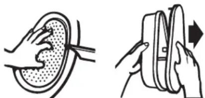
- Open the door and pull the lint screen straight out.
natural_image
Illustration showing two hands performing a medical or surgical procedure: one intact ear with bandage, the other with bandage and forceps (no text or symbols)- Squeeze body of lint screen lightly while pulling off the cover.
- Roll lint off the screen with your fingers. Do not rinse or wash screen to remove lint. Wet lint is hard to remove.
- Replace cover on lint screen body. Push the lint screen firmly back into place and close the door.
IMPORTANT:
■Do not run the dryer with the lint screen loose, damaged, blocked, or missing. Doing so can cause overheating and damage to both the dryer and fabrics.
As needed cleaning
Laundry detergent and fabric softener residue can build up on the lint screen. This buildup can cause longer drying times for your clothes, or cause the dryer to stop before your load is completely dry. The screen is probably clogged if lint falls off the screen.
Clean the lint screen with a nylon brush every 6 months, or more frequently if it becomes clogged due to a residue buildup.
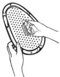
To wash:
- Roll lint off the screen with your fingers.
- Wet both the lint screen cover and body with hot water.
- Wet a nylon brush with hot water and liquid detergent. Scrub lint screen cover and body with the brush to remove residue buildup.
natural_image
Illustration of hands holding a perforated tray with a small object inside (no text or symbols)- Rinse with hot water.
- Thoroughly dry lint screen body and cover with a clean towel. Replace in dryer.
Cleaning the Dryer Interior
To clean dryer drum:
- Make a paste with powdered laundry detergent and very warm water.
- Apply paste to a soft cloth. OR
Apply a liquid, nonflammable household cleaner to the stained area and rub with a soft cloth until all excess dye is removed.
-
Wipe drum thoroughly with a damp cloth.
-
Tumble a load of clean cloths or towels to dry drum.
NOTE: Garments that contain unstable dyes, such as denim blue jeans or brightly colored cotton items, may discolor the dryer interior. These stains are not harmful to your dryer and will not stain future loads of clothes. Dry unstable dye items inside-out to avoid transfer of dye.
Removing Accumulated Lint
From Inside the Dryer Cabinet
Lint should be removed every 2 years, or more often, depending on dryer usage. Cleaning should be done by a qualified person.
From the Exhaust Vent
Lint should be removed every 2 years, or more often, depending on dryer usage.
Vacation and Moving Care
Vacation Care
Operate your dryer only when you are at home. If you will be on vacation or not using your dryer for an extended period of time, you should:
- Unplug dryer or disconnect power.
- Clean lint screen. See "Cleaning the Lint Screen."
Moving Care
- Unplug the power supply cord.
- Use tape to secure dryer door.
Troubleshooting
| First try the solutions suggested here or visit our website at www.amana.custhelp.com - In Canada www.amanacanada.ca for assistance and to possibly avoid a service call. | ||
| If you experience Possible Causes Solution | ||
| Dryer Operation | ||
| Dryer will not run Door not | closed completely. Make sure the dryer | door is closed completely. |
| Press and hold the START button 2-5 seconds. | Press and hold the START button 2-5 seconds. | |
| Household fuse is blown or circuit breaker has tripped. | There is be a household fuse or circuit breaker for the dryer. Check that the fuse is intact and tight, or that the circuit breaker has not tripped. Replace the fuse or reset the circuit breaker. If the problem continues, call an electrician. | |
| Incorrect power supply. Electric dryers | require 120-volt power supply. Check with a qualified electrician. | |
| Wrong type of fuse. Use a time-delay fuse. | require 120-volt power supply. Check with a qualified electrician. | |
| Incorrect power supply. Electric dryers | requires 120-volt power supply. Check with a qualified electrician. | |
| Timer does not noticeably advance | Dryer set to Timed or Air Dry The timer | moves slowly and continuously for the time setting. |
| Dryer set to Auto Dry The timer moves | only when the clothing is mostly dry. See “How Auto Moisture Sensing Works” in “Dryer Use.” | |
| Unusual Noise | ||
| Thumping noise | Dryer hasn’t been used in a while. | This is normal. The thumping sound should diminish after a few minutes of use. |
| Rattling or vibrating noise | A small object caught between the edges of dryer drum. | Check the front and rear edges of the drum for small objects. Clean out pockets before laundering. |
| Dryer isn’t properly leveled. The dryer | may vibrate if not properly installed. Check the levelness of the dryer. All four casters should be in firm contact with the floor. | |
| Clothing is balled up in dryer. When balled up, the load will bounce, causing the dryer to vibrate. Separate the load items and restart the dryer. | ||
WARNING

Fire Hazard
Use a heavy metal vent.
Do not use a plastic vent.
Do not use a metal foil vent.
Failure to follow these instructions can result in death or fire.
WARNING
Explosion Hazard
Keep flammable materials and vapors, such as gasoline, away from dryer.
Place dryer at least 18 inches (460 mm) above the floor for a garage installation.
Failure to do so can result in death, explosion, or fire.
Dryer Results
| NOTE: The compact dryer operates at a lower wattage. Expect longer drying times. | ||
| Clothes are not drying satisfactorily or drying times are too long | Lint screen is clogged with lint. Clean lint | int screen before each load. |
| The exhaust vent or outside exhaust hood is clogged with lint, restricting air movement. | Run the dryer for 5–10 minutes. Hold your hand under the outside exhaust hood to check air movement. If you do not feel air movement, clean exhaust system of lint or replace exhaust vent with heavy metal or flexible metal vent. See “Venting.” | |
Troubleshooting
| First try the solutions suggested here or visit our website at www.amana.custhelp.com - In Canada www.amanacanada.ca for assistance and to possibly avoid a service call. | ||
| If you experience Possible Causes Solution | ||
| Dryer Results | ||
| Clothes are not drying satisfactorily or drying times are too long (cont.) | The exhaust vent is not the correct length. | Check that the exhaust vent is not too long or has too many turns. Long venting will increase drying times. See “Venting.” |
| The exhaust vent diameter is not the correct size. | Use 4" (102 mm) diameter vent material. | |
| The dryer is not level. Clothes not contacting the moisture sensors during Automatic cycles. Check the levelness of the dryer. All four casters should be in firm contact with the floor. | ||
| The Air Dry temperature setting has been selected. | Select the correct temperature for the types of garments being dried. See “Cycles.” | |
| The load is too large and heavy to dry quickly. | Separate the load to tumble freely. | |
| Fabric softener sheets are blocking the lint screen cover. | Use only one fabric softener sheet, and use it only once. | |
| The dryer is located in a room with temperature below 45°F (7°C). | Proper operation of dryer cycles requires temperatures above 45°F (7°C). | |
| The dryer is located in a closet. Closet doors must have ventilation openings at the top and bottom of the door. The front of the dryer requires a minimum of 1” (25 mm) of airspace, and, for most installations, the rear of the dryer requires 51⁄2” (140 mm). See “Location Requirements.” | ||
| The load may not be contacting the sensor strips on Sensor Cycles. | Check the levelness of the dryer. All four casters should be in firm contact with the floor. | |
| Cycle time is too short | The sensor cycle is ending early. | Change the dryness level setting on sensor cycles. Increasing or decreasing the dryness level will change the amount of drying time in a cycle. If loads are consistently ending too early, see “Cycles.” |
| Lint on load Lint screen is clogged with lint. Clean lint screen before each load. | ||
| Stains on load Improper use of fabric softener. Add dryer fabric softener sheets at the beginning of the cycle.Fabric softener sheets added to a partially dried load can stain your garments. | ||
| Stains on drum Loose dyes in clothes. Drum stains are caused by dyes in clothing (usually blue jeans).These will not transfer to other clothing. | ||
| Loads are wrinkled The load was not removed from dryer at the end of the cycle. | Refer to garment care label instructions. Dry clean only garments are not recommended. | |
| Odors Recent painting, staining, or varnishing in the area where your dryer is located. | Ventilate the area. When the odors or fumes are gone from the area, rewash and dry the clothing. | |
Accessories
Part Number Accessory
49971 Compact dryer stand - white
For ordering information, see "Assistance or Service" on the back page.
AMANA® MAJOR APPLIANCE LIMITED WARRANTY
ATTACH YOUR RECEIPT HERE. PROOF OF PURCHASE IS REQUIRED TO OBTAIN WARRANTY SERVICE.
Please have the following information available when you call the Customer eXperience Center:
■Name, address and telephone number
■Model number and serial number
■A clear, detailed description of the problem
■Proof of purchase including dealer or retailer name and address
IF YOU NEED SERVICE:
- Before contacting us to arrange service, please determine whether your product requires repair. Some questions can be addressed without service. Please take a few minutes to review the Troubleshooting or Problem Solver section of the Use and Care Guide, scan the QR code on the right to access additional resources, or visit http://amana.custhelp.com.
- All warranty service is provided exclusively by our authorized Amana Service Providers. In the U.S. and Canada, direct all requests for warranty service to:
Amana Customer eXperience Center
In the U.S.A., call 1-800-843-0304. In Canada, call 1-800-807-6777.
If outside the 50 United States or Canada, contact your authorized Amana dealer to determine whether another warranty applies.

http://amana.custhelp.com
ONE YEAR LIMITED WARRANTY
WHAT IS COVERED WHAT IS NOT COVERED
For one year from the date of purchase, when this major appliance is installed, operated and maintained according to instructions attached to or furnished with the product, Amana brand of Whirlpool Corporation or Whirlpool Canada LP (hereafter “Amana”) will pay for Factory Specified Replacement Parts and repair labor to correct defects in materials or workmanship that existed when this major appliance was purchased, or at its sole discretion replace the product. In the event of product replacement, your appliance will be warranted for the remaining term of the original unit's warranty period.
YOUR SOLE AND EXCLUSIVE REMEDY UNDER THIS LIMITED WARRANTY SHALL BE PRODUCT REPAIR AS PROVIDED HEREIN. Service must be provided by a Amana designated service company. This limited warranty is valid only in the United States or Canada and applies only when the major appliance is used in the country in which it was purchased. This limited warranty is effective from the date of original consumer purchase. Proof of original purchase date is required to obtain service under this limited warranty.
- Commercial, non-residential, multiple-family use, or use inconsistent with published user, operator or installation instructions.
- In-home instruction on how to use your product.
- Service to correct improper product maintenance or installation, installation not in accordance with electrical or plumbing codes or correction of household electrical or plumbing (i.e. house wiring, fuses or water inlet hoses).
- Consumable parts (i.e. light bulbs, batteries, air or water filters, preservation solutions, etc.).
- Defects or damage caused by the use of non-genuine Amana parts or accessories.
-
Conversion of products from natural gas or L.P. gas.
-
Damage from accident, misuse, abuse, fire, floods, acts of God or use with products not approved by Amana.
-
Repairs to parts or systems to correct product damage or defects caused by unauthorized service, alteration or modification of the appliance.
-
Cosmetic damage including scratches, dents, chips, and other damage to the appliance finishes unless such damage results from defects in materials and workmanship and is reported to Amana within 30 days.
-
Discoloration, rust or oxidation of surfaces resulting from caustic or corrosive environments including but not limited to high salt concentrations, high moisture or humidity or exposure to chemicals.
-
Food or medicine loss due to product failure.
-
Pick-up or delivery. This product is intended for in-home repair.
-
Travel or transportation expenses for service in remote locations where an authorized Amana servicer is not available.
-
Removal or reinstallation of inaccessible appliances or built-in fixtures (i.e. trim, decorative panels, flooring, cabinetry, islands, countertops, drywall, etc.) that interfere with servicing, removal or replacement of the product.
-
Service or parts for appliances with original model/serial numbers removed, altered or not easily determined.
The cost of repair or replacement under these excluded circumstances shall be borne by the customer.
DISCLAIMER OF IMPLIED WARRANTIES
IMPLIED WARRANTIES, INCLUDING ANY IMPLIED WARRANTY OF MERCHANTABILITY OR IMPLIED WARRANTY OF FITNESS FOR A PARTICULAR PURPOSE, ARE LIMITED TO ONE YEAR OR THE SHORTEST PERIOD ALLOWED BY LAW. Some states and provinces do not allow limitations on the duration of implied warranties of merchantability or fitness, so this limitation may not apply to you. This warranty gives you specific legal rights, and you also may have other rights that vary from state to state or province to province.
DISCLAIMER OF REPRESENTATIONS OUTSIDE OF WARRANTY
Amana makes no representations about the quality, durability, or need for service or repair of this major appliance other than the representations contained in this warranty. If you want a longer or more comprehensive warranty than the limited warranty that comes with this major appliance, you should ask Amana or your retailer about buying an extended warranty.
LIMITATION OF REMEDIES; EXCLUSION OF INCIDENTAL AND CONSEQUENTIAL DAMAGES
YOUR SOLE AND EXCLUSIVE REMEDY UNDER THIS LIMITED WARRANTY SHALL BE PRODUCT REPAIR AS PROVIDED HEREIN. AMANA SHALL NOT BE LIABLE FOR INCIDENTAL OR CONSEQUENTIAL DAMAGES. Some states and provinces do not allow the exclusion or limitation of incidental or consequential damages, so these limitations and exclusions may not apply to you. This warranty gives you specific legal rights, and you also may have other rights that vary from state to state or province to province.
natural_image
Line drawing of a screwdriver with a flat head and threaded shaft (no text or symbols)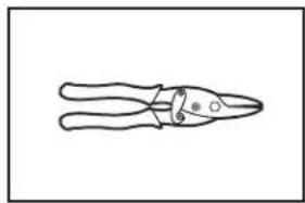
natural_image
Simple line drawing of a pair of pliers (no text or symbols)natural_image
Simple line drawing of a rectangular object with three circular holes, no text or symbols present.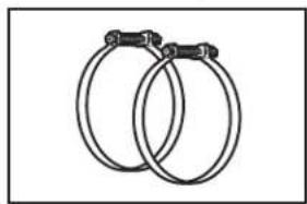
natural_image
Two interlocked rings with metal clips (no text or symbols)natural_image
Line drawing of an adjustable wrench (no text or symbols)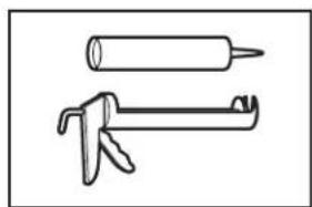
natural_image
Two types of hand tools: a cylindrical tool and a mechanical tool (no text or symbols)natural_image
Simple geometric diagram with concentric circles and a shaded central region (no text or symbols)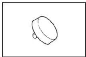
natural_image
Simple line drawing of a cylindrical object with a protruding shaft (no text or symbols)natural_image
Illustration of four different types of wheel switches with threaded pins (no text or symbols)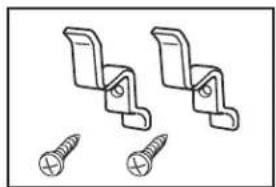
natural_image
Technical line drawing of two bracket fasteners with screw holes (no text or symbols)Roulettes (4) Supports du cordon (2) et vis (2)
Pièces nécessaires
text_image
4" (102 mm)natural_image
Simple line drawing of a vent or airflow device with no text or symbols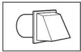
natural_image
Simple line drawing of a 3D object resembling a folded paper or bracket (no text or symbols)natural_image
Simple line drawing of a mechanical component or bracket (no text or symbols)Type incliné
Coudes
natural_image
Simple line drawing of a pipe passing through a circular opening with a ring attached (no text or symbols)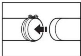
natural_image
Pure mechanical diagram showing a rotating component with a directional arrow, no text or symbols presentnatural_image
Diagram of a bent pipe with two bolts and a magnified inset showing internal structure (no text or symbols)
natural_image
Pure technical line drawing of a mechanical component without any text, numbers, or symbolsA
B
natural_image
Simple line drawing of a vertical ruler measuring a rectangular object on a horizontal surface (no text or symbols)natural_image
Pure technical line drawing of a mechanical component with no text or symbolsnatural_image
Technical line drawing of a curved pipe or duct with hatched fill and a vertical support (no text or symbols)text_image
Technical diagram of an electrical enclosure with labeled components A, B, and C, showing internal wiring and a magnified inset view.natural_image
Technical line drawing of a mechanical pulley system with a rope and lever (no text or symbols)natural_image
Technical line drawing of a mechanical component with a circular opening and coiled tubing (no text or symbols)natural_image
Line drawing of a simple kitchen oven with a door and side panel, no text or symbols presentnatural_image
Simple line drawing of a fan or vent with internal blades, no text or symbols presentAVERTISSEMENT

Risque d'incendie
natural_image
Illustration showing two hands performing a physical manipulation or cleaning operation (no text or symbols present)natural_image
Line drawing of hands holding a perforated metal tray (no text or symbols)ASSISTANCE OR SERVICE
Before calling for assistance or service, please check "Troubleshooting" or visit www.whirlpool.com/product_help. It may save you the cost of a service call. If you still need help, follow the instructions below.
When calling, please know the purchase date and the complete model and serial number of your appliance. This information will help us to better respond to your request.
If you need replacement parts or to order accessories
We recommend that you use only FSP® Factory Specified Parts.
These parts will fit right and work right because they are made with the same precision used to build every new Amana, Admiral, Estate, Inglis, or Roper brands of Whirlpool Corporation or Whirlpool Canada LP appliance.
To locate FSP ^® replacement parts, assistance in your area, or accessories:
Whirlpool Corporation Customer eXperience Center
800-843-0304 for Amana, 800-688-9920 for Admiral,
800-253-1301 for Estate, or 800-447-6737 for Roper
800-442-9991 (Accessories)
www.whirlpool.com/accessories
Whirlpool Canada LP
Customer eXperience Centre
800-807-6777 for
Amana, Admiral, Estate, Inglis, & Roper
www.whirlpoolappliances.ca
or call your nearest designated service center or refer to your Yellow Pages telephone directory.
Our consultants provide assistance with
In the U.S.A.
■Features and specifications on our full line of appliances.
■Installation information.
■Specialized customer assistance (Spanish speaking, hearing impaired, limited vision, etc.).
In the U.S.A. and Canada
■Use and maintenance procedures.
■Accessory and repair parts sales.
■Referrals to local dealers, repair parts distributors, and service companies. Whirlpool designated service technicians are trained to fulfill the product warranty and provide after-warranty service, anywhere in the United States and Canada.
You can write with any questions or concerns at:
Whirlpool Corporation
Customer eXperience Center
553 Benson Road
Benton Harbor, MI 49022-2692
Customer eXperience Centre
Whirlpool Canada LP
Unit 200-6750 Century Ave
Mississauga, Ontario L5N 0B7
Please include a daytime phone number in your correspondence.