
CPE520 - Access Point TP-LINK - Free user manual and instructions
Find the device manual for free CPE520 TP-LINK in PDF.
| Product type | Outdoor Access Point (CPE) |
| Brand | TP-Link |
| Model | CPE520 |
| Dimensions (L x W x H) | 280 x 80 x 45 mm |
| Weight | 1.2 kg |
| Power supply | PoE 802.3af (injector or PoE switch) |
| Frequency | 5 GHz |
| Maximum data rate | 300 Mbps |
| Wi-Fi standards | 802.11a/n |
| Ports | 1 x Gigabit Ethernet (PoE in) |
| Antennas | Integrated, 2x2 MIMO |
| Operating temperature | -30 °C to 70 °C |
| Weather protection | IP65 rating (weather-resistant) |
| Management modes | Standalone (web interface) or centralized (Omada software/controller) |
| Installation | On pole or wall (mounting kit included) |
| Security | WPA2, WPA3, MAC filtering, client isolation |
| Maintenance and cleaning | Clean with a soft, dry cloth. Disconnect before cleaning. |
| Spare parts and repairability | No spare parts available. Contact TP-Link customer service. |
Frequently Asked Questions - CPE520 TP-LINK
User questions about CPE520 TP-LINK
0 question about this device. Answer the ones you know or ask your own.
Ask a new question about this device
Download the instructions for your Access Point in PDF format for free! Find your manual CPE520 - TP-LINK and take your electronic device back in hand. On this page are published all the documents necessary for the use of your device. CPE520 by TP-LINK.
USER MANUAL CPE520 TP-LINK
Note: The image may differ from the actual product.
Typical Network Topology
■ Managed Mode
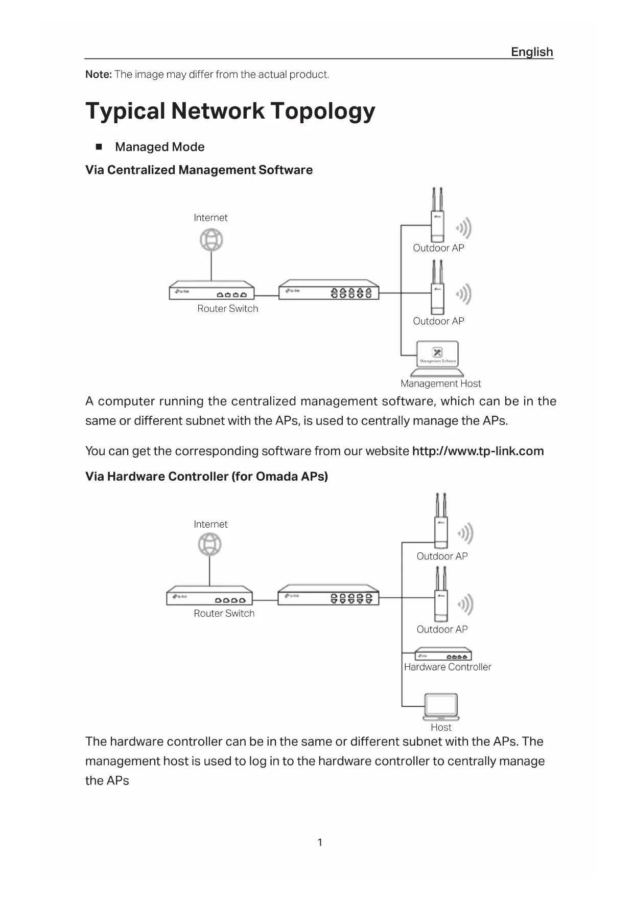
Via Centralized Management Software
flowchart
graph LR
    A["Internet"] --> B["Router Switch"]
    B --> C["Network Switch"]
    C --> D["Outdoor AP"]
    C --> E["Outdoor AP"]
    C --> F["Management Host"]
A computer running the centralized management software, which can be in the same or different subnet with the APs, is used to centrally manage the APs.
You can get the corresponding software from our website http://www.tp-link.com
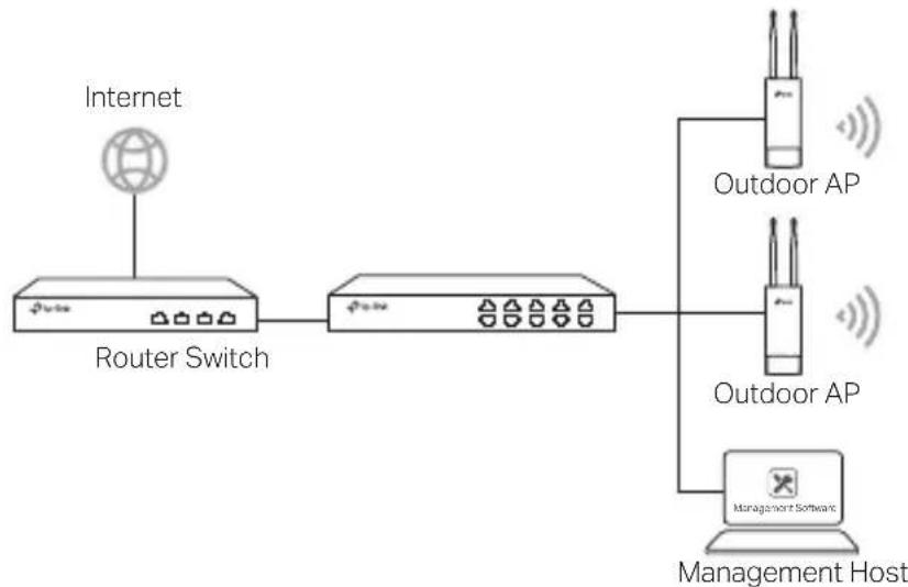
Via Hardware Controller (for Omada APs)
flowchart
graph LR
    A["Internet"] --> B["Router Switch"]
    B --> C["Outdoor AP"]
    B --> D["Outdoor AP"]
    B --> E["Hardware Controller"]
    E --> F["Host"]
The hardware controller can be in the same or different subnet with the APs. The management host is used to log in to the hardware controller to centrally manage the APs
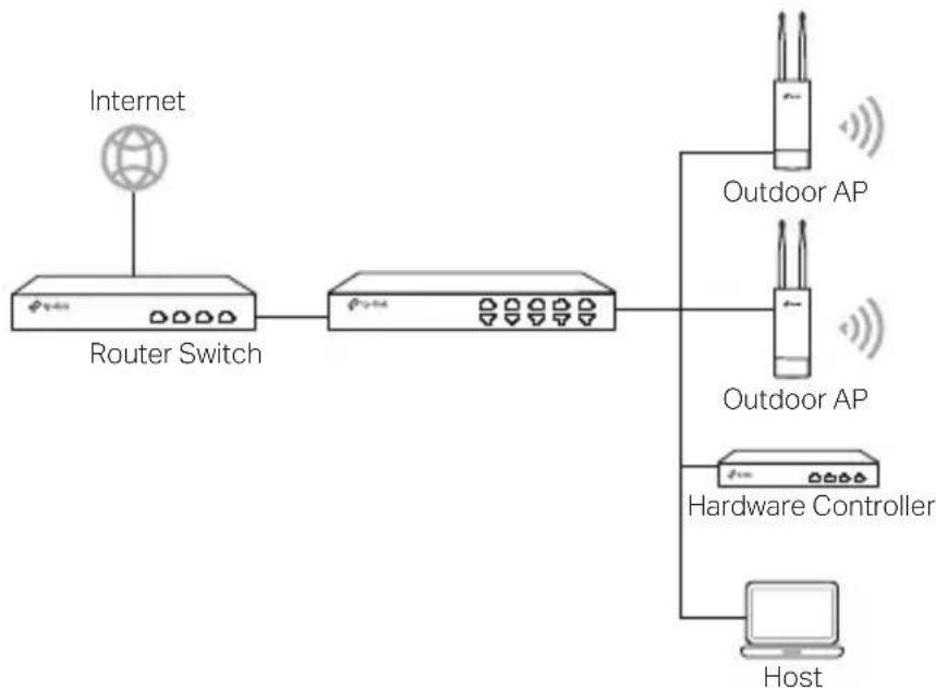
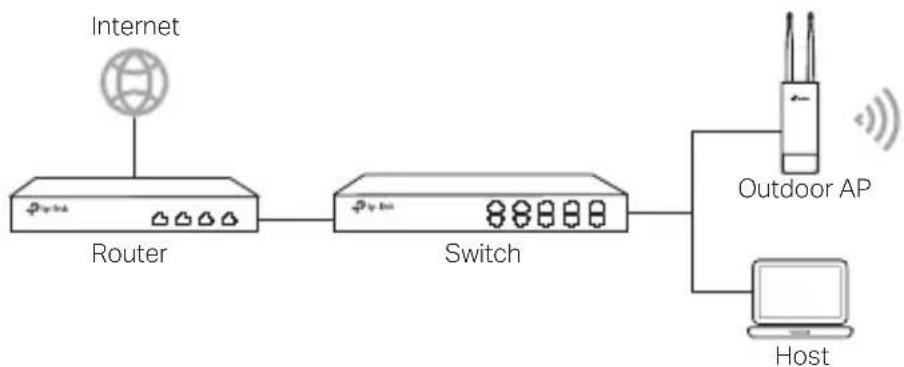
■ Standalone Mode
flowchart
graph LR
    A["Internet"] --> B["Router"]
    B --> C["Switch"]
    C --> D["Outdoor AP"]
    D --> E["Host"]
Hardware Connection
Choose a method to connect your device according to the accessories.
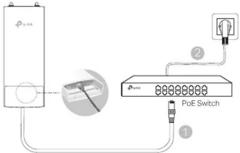
■ Via PoE Switch
Some APs can be powered via the PSE device (such as a PoE switch) which complies with Power Source Class 2 (PS2) or Limited Power Source (LPS) of IEC 62368-1.
Note: Availability depends on the actual product. Please refer to the product specifications.
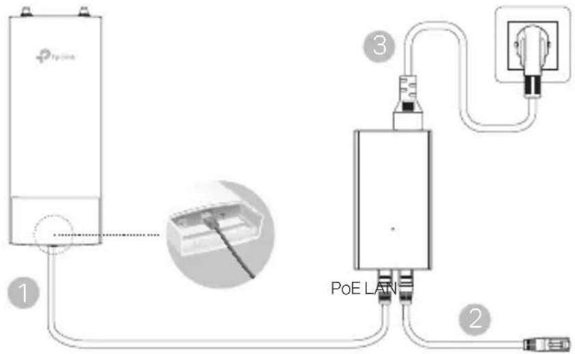
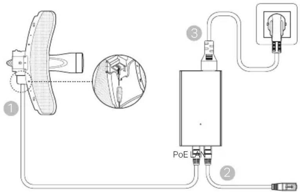
■ Via PoE Adapter
Some APs can be powered via the PoE adapter.
Note: Availability depends on the actual product. Please refer to the product specifications.
Or
Hardware Installation
- Choose a method to mount the device.
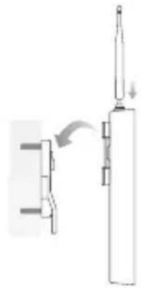
■ Mounting the Device on a Pole
At the selected site, attach the device to a suitable point of the pole and then approximately align the device to the direction that you have oriented.
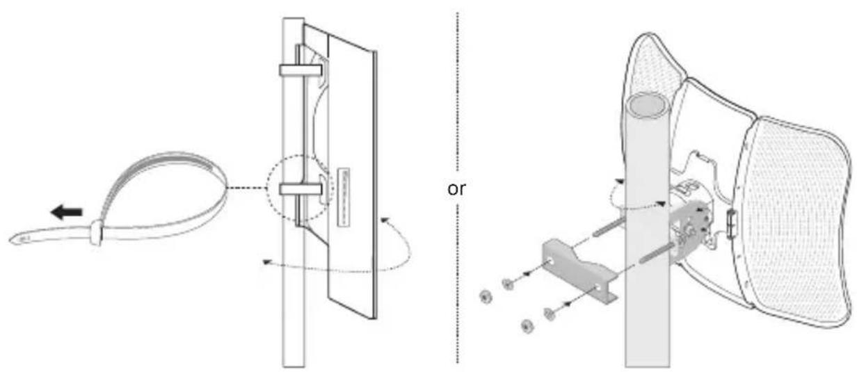
■ Mounting the Device on the Wall (for the product with mounting brackets)
Mount the mounting bracket to the preferred position in the wall Push and slide the device to lock it into place. Then connect the antennas to the device.
natural_image
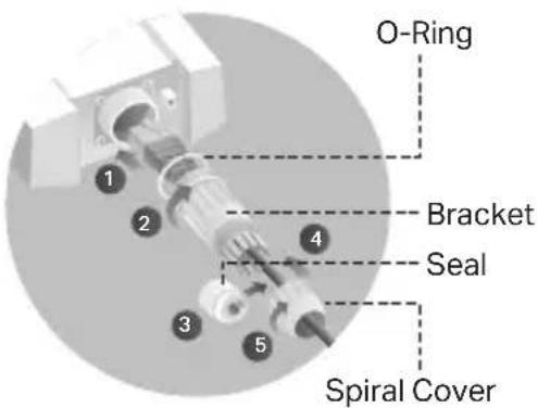
Diagram showing a mechanical assembly with a cylindrical component and a vertical rod, no text or symbols present.2. Install the waterproof seal. (For certain devices)
Before installing, fit the Ethernet cable through the spiral cover, bracket, and O-ring. Then follow the steps as shown in the picture:
(1) Connect the Ethernet cable to the port.
(2) Fit the O-Ring to the head of the bracket, and screw the bracket to the body of the device.
(3) Fit the Ethernet cable through the seal's slit with the thicker side towards the bracket
(4) Plug the seal to the bracket.
(5) Screw the spiral cover to the bracket.
Software Configurations
■ Managed Mode
To configure mass devices via a centralized management software or a wireless controller, please refer to the corresponding User Guide You can download the User Guide from our website http://www.tp-link.com
■ Standalone Mode
To configure a device through a web-based management system, please follow the steps below
- Launch a web browser and enter the IP address of your device in the address bar and press Enter
Note:
- For Omada APs, you can check the IP address through the product label.
-
For other products, the default IP address is 192.168.0.254 and the IP address of your computer should be set as 192.168.0.x ("x" is any number from 1 to 253).
-
Enter admin for both User Name and Password for login
-
Change the default User Name and Password to protect your device, then start configuring the device.
natural_image
Technical diagram showing two mechanical assembly configurations with labeled parts and motion indicators (no text or symbols present)natural_image
Diagram showing a mechanical assembly with a lever and a vertical component, no text or symbols presentnatural_image
Pure mechanical diagram showing a lever and shaft assembly without any text, numbers, or symbolsnatural_image
Simple line drawing of a mechanical assembly with no text or symbolsFor technical support, the user guide and other information, please visit https://www.tp-link.com/support/, or simply scan the QR code.