VSBO2402SS - Barbecue VIKING - Free user manual and instructions
Find the device manual for free VSBO2402SS VIKING in PDF.
| Brand | Viking |
| Model | VSBO2402SS |
| Product type | Built-in gas grill |
| Material | Stainless steel |
| Gas type | Propane or natural gas (depending on configuration) |
| Burner power | Not specified (estimated high performance) |
| Cooking surface | Stainless steel grate |
| Side burners | Possibility to add a side burner or electric burner (optional) |
| Ignition | Electronic ignition (integrated) |
| Dimensions (W x D x H) | Approximately 87.6 cm width (opening) × 53.3 cm depth × 91.4 cm height (estimated) |
| Weight | Approximately 68 kg (estimated) |
| Power supply | 120 V AC, 60 Hz for lighting and accessories |
| Maintenance and cleaning | Clean stainless steel with a specialized product (e.g., Magic for stainless steel), avoid chlorine and abrasives |
| Safety | Never store propane cylinders inside the enclosure; follow safety distances |
| Spare parts and repairability | Authorized Viking parts required to maintain warranty; authorized after-sales service |
| Warranty | 2 years full warranty on materials and workmanship (parts and labor), 90 days on cosmetic finishes |
| Installation | Built-in in an island or against a wall; requires countertop at least 2.9 cm thick |
| Intended use | Outdoor domestic use |
| Country of manufacture | United States (Viking Range, LLC) |
Frequently Asked Questions - VSBO2402SS VIKING
User questions about VSBO2402SS VIKING
0 question about this device. Answer the ones you know or ask your own.
Ask a new question about this device
Download the instructions for your Barbecue in PDF format for free! Find your manual VSBO2402SS - VIKING and take your electronic device back in hand. On this page are published all the documents necessary for the use of your device. VSBO2402SS by VIKING.
USER MANUAL VSBO2402SS VIKING
Use / Install MANUAL
natural_image
Exterior view of a white electric stove burner with control knobs and doors (no visible text or symbols)Outdoor Stainless Steel Cabinets
VBBO1601 / VBBO2602 / VBBO5160 / VBBO5260
VURO3200 / VBO1811 / VBO1830 / VSBO2402 / VTOP1810
VQBO4121 / VQBO5322 / VQBO5420 / VQBO5540 / VQWO4120 / VQWO5311
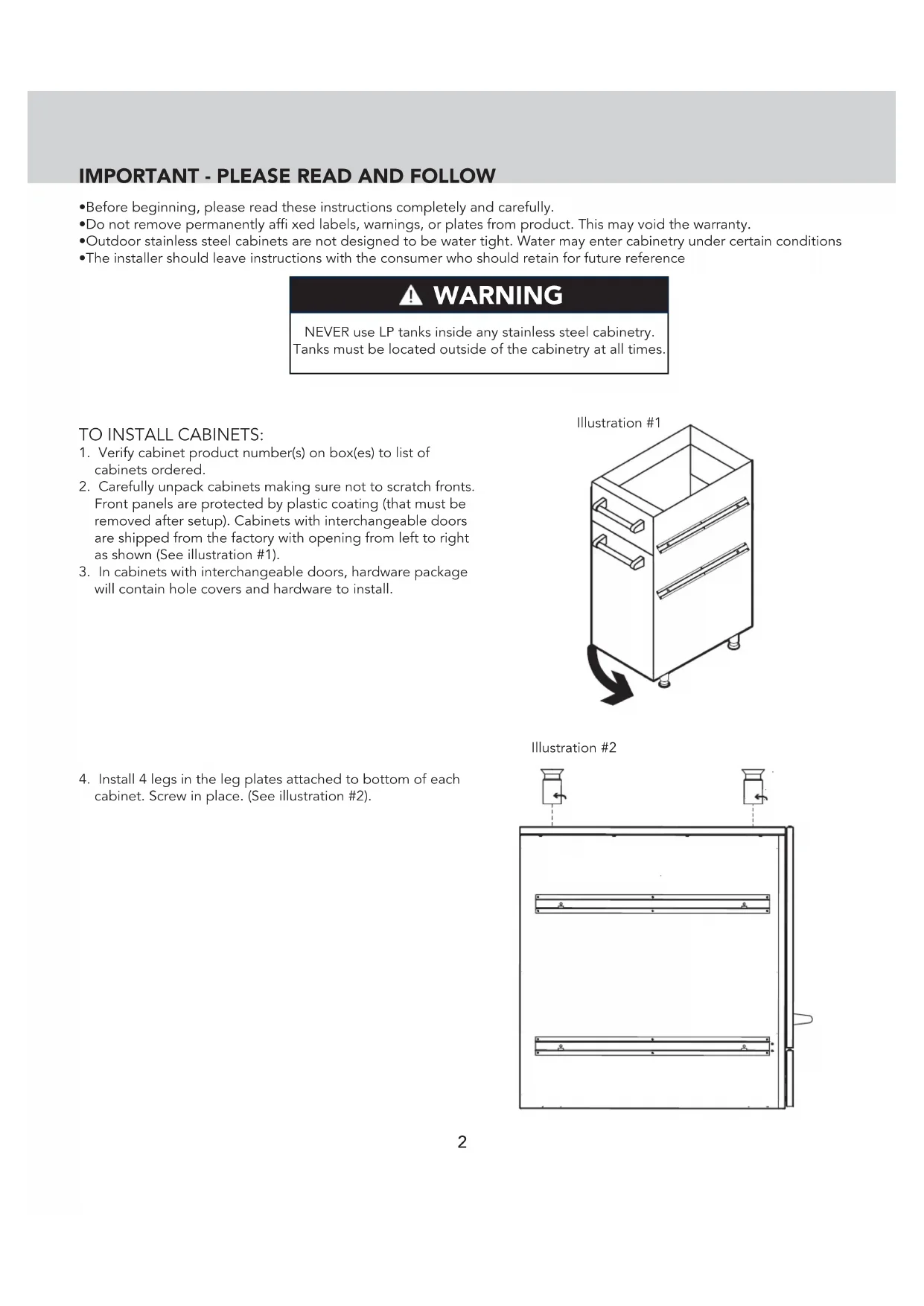
IMPORTANT - PLEASE READ AND FOLLOW
- Before beginning, please read these instructions completely and carefully.
- Do not remove permanently affi xed labels, warnings, or plates from product. This may void the warranty.
•Outdoor stainless steel cabinets are not designed to be water tight. Water may enter cabinetry under certain conditions
•The installer should leave instructions with the consumer who should retain for future reference
WARNING
NEVER use LP tanks inside any stainless steel cabinetry. Tanks must be located outside of the cabinetry at all times.
TO INSTALL CABINETS:
- Verify cabinet product number(s) on box(es) to list of cabinets ordered.
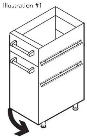
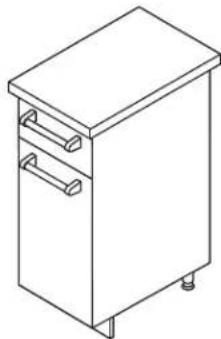
- Carefully unpack cabinets making sure not to scratch fronts. Front panels are protected by plastic coating (that must be removed after setup). Cabinets with interchangeable doors are shipped from the factory with opening from left to right as shown (See illustration #1).
-
In cabinets with interchangeable doors, hardware package will contain hole covers and hardware to install.
-
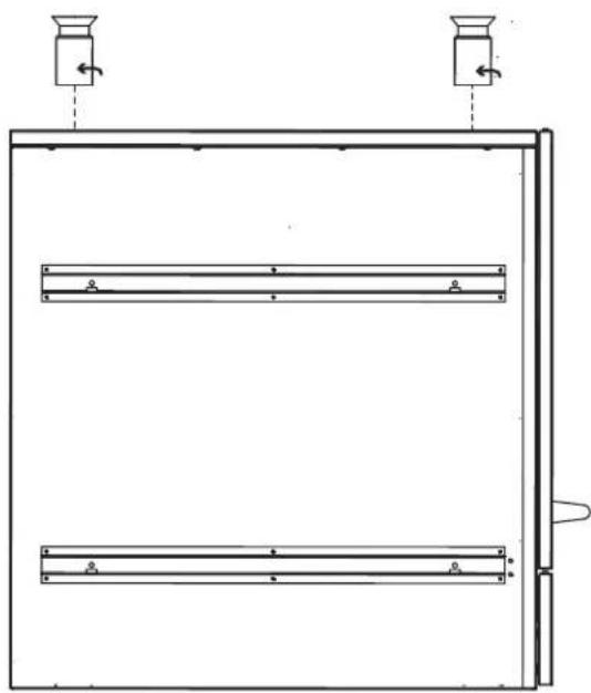
Install 4 legs in the leg plates attached to bottom of each cabinet. Screw in place. (See illustration #2).
natural_image
Line drawing of a cabinet with drawers and handle, labeled 'Illustration #1' (no other text or symbols)Illustration #2
natural_image
Pure technical line drawing of a mechanical or architectural component with no text, numbers, or symbolsIMPORTANT - PLEASE READ AND FOLLOW!
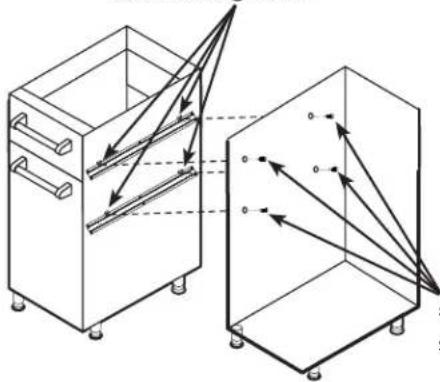
- Place cabinet(s) in approximate final position. Level cabinets using leveling legs. If installing two or more cabinets, use 1/2" SMS screws provided to screw them together. (See illustration #3).
Illustration #3
Install (4) Tinnerman clips (provided) before fastening cabinets together.
natural_image
Technical line drawing of two 3D cabinet-like structures with internal arrows indicating flow or movement (no text or symbols)Mount cabinets with #10 x 1/2" (1.3 cm) screws provided.
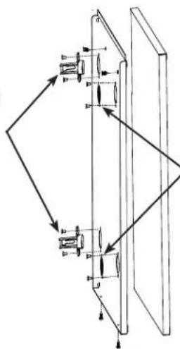
- On cabinets with interchangeable left or right hand swing, determine appropriate hinge side for cabinets. Remove outside door panel. Install hinges by placing hinge bracket in hole in door and fasten in place with hardware provided. Screw hole plate covers in appropriate pre-drilled holes in cabinet side. Fasten hole covers with hardware provided. (See Illustration #4).
Use #8 x 3/8" (.95 cm) fl at head M.S. and locknut to attach hinge bracket to the inside door
natural_image
Pure mechanical diagram showing linkage between two components with arrows indicating motion (no text or symbols)Use #8 x 3/8" (.95 cm) M.S. and locknut to fasten hole cover to inside door panel.
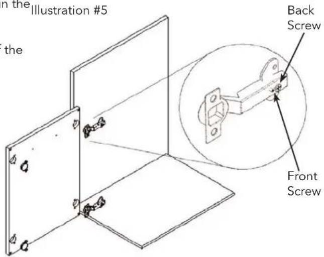
- Cabinet doors must be adjusted when cabinets are level in final position. There are two adjustment screws on the hinge receiver. (See Illustration #5)
- The front screw is used to center the door in the Illustration #5 opening. Turning the front screws in or out will center the door over the cabinet opening.
- The back screw is used to align the front of the door with the cabinet frame and secure the door to the cabinet. Slightly loosen the screw and slide door in or out. Retighten the screw to secure the door.
INSTALLATION
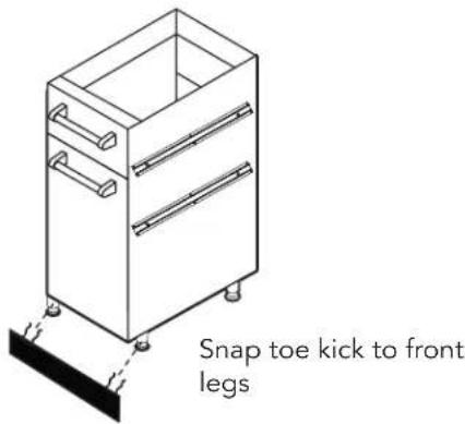
- If desired, snap toe kick included with each unit to front legs. (See illustration #6).
Illustration #6
9. SIDE PANEL INSTALLATION (End of Run Only)
- Remove all drawers. (If applicable)
- Remove all protective covering from panel and install using the #10 x 1/2" tek screws provided. (See Illustration #7)
- Attach toe kick to legs (See Illustration #6).
NOTE: FOR WALL INSTALLATIONS:
The front portion of the side toe kick must be shortened to match the front toe kick. (See Illustration #7). The plastic material can be cut with any common type wood saw blade.
FOR ISLAND INSTALLATIONS:
The side, front, and rear toe kick must be modified (See Illustration #7)
Illustration #7
- Attach from inside (front and rear)
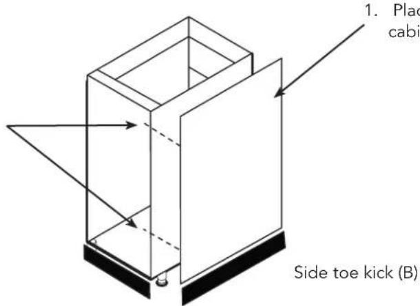
- Place side panel into area of the cabinet.
toe kick (A)
LH Side panel Installation shown (RH installs the same way)
| Toe Kick DimensionsWall Installation Island Installation | ||
| Front Toe Kick (A) 16 | 3/4" (42.5 cm) 16 3/4" (42.5 cm) | |
| Side Toe Kick (B) 27 | 1/4" (61.6 cm) 25 1/2" (64.8 cm) | |
| Rear Toe Kick (C) N/A | 16 3/4" (42.5 cm) | |
INSTALLATION
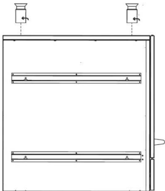
10. BACK PANEL INSTALLATION
- Remove all protective covering from panel and install using the 10 × 1/2'' tek screws provided. (See Illustration #8).
- Attach rear toe kick to legs. (See illustration #8).
NOTE: For end of the run panels, the rear, front, and side toe kicks must be modified. (See illustrations #7 & #8)
Illustration #8
- Attach from inside with (4) tek screws provided. (front and rear)
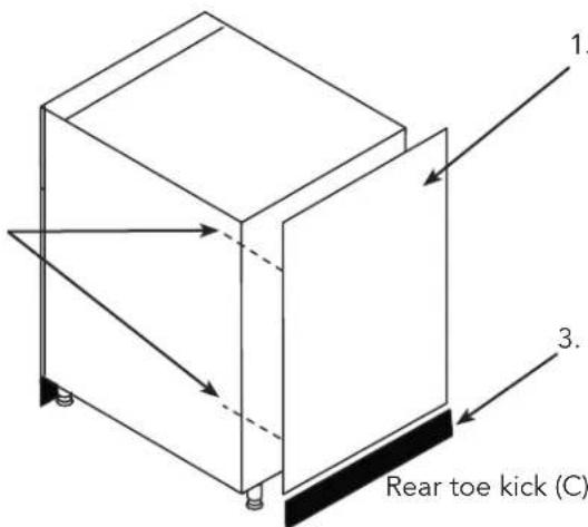
- Place rear panel into area of the cabinet.
- After modifying rear toe kick (See dimension chart at the bottom of page 4) - snap toe kick into place
All Vikiong outdoor cabinets must be installed with a locally supplied counterop. The cabinets are designed for a minimum countertop thickness of 1 1/8" (2.9 cm) such as you would find with granite or quartz material. If a countertop material thicker than 1 1/2" (3.8 cm) is used, the appliances should be shimmed to the proper height.
- Install per appliance's installation instructions.
natural_image
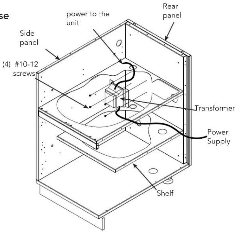
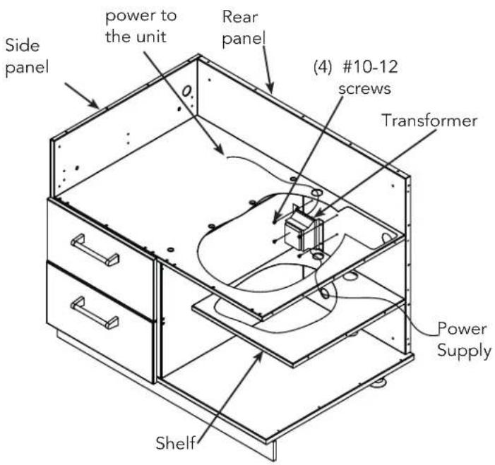
Line drawing of a simple cabinet with two drawers and a lid (no text or symbols)Installing the Transformer on Grill Base
For Models VBBO5160 / VBBO5260
- The transformer must be mounted inside the cabinet
- If you are installing a Viking grill on either side of the burner, there is a hole on either side of the cabinet provided in order to connect the grill to the side or power burner unit.
- If you are not are installing a Viking grill on either side, locate the four holes in the back panel and feed the AC plug through the hole in the shelf and out the hole in the rear panel.
- Line up the holes in the transformer with the holes in the rear panel.
- Using the (4) #10-12 screws that were provided, attach with a drill with a T25 torx bit to secure the transformer to the rear panel.
- Feed the connector through the hole above to connect it to the side or power burner unit.
For Models VQBO5420
- The transformer must be mounted inside the cabinet
- Locate the four holes in the back panel and feed the AC plug through the hole in the shelf and out the hole in the rear panel.
- Line up the holes in the transformer with the holes in the rear panel.
- Using the (4) #10-12 screws that were provided, attach with a drill with a T25 torx bit to secure the transformer to the rear panel.
- Feed the connector through the hole above to connect it to the grill
- If you are installing a Viking side burner or power burner on either side of the grill, there is a hole on either side of the cabinet provided to feed the connector from the grill to the burners.
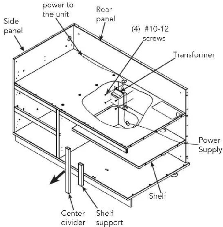
Installing the Transformer on Grill Base
For Models VQBO5540
- The transformer must be mounted inside the cabinet
- Grip the center divider between the two doors inside the cabinet and firmly pull it straight out.
- Grip the shelf support (behind the center divider that was just removed) and firmly pull it straight out.
- Locate the four holes in the back panel and feed the AC plug through the hole in the shelf and out the hole in the rear panel.
- Line up the holes in the transformer with the holes in the rear panel
- Using the (4) #10-12 screws that were provided, attach with a drill with a T25 torx bit to secure the transformer to the back panel.
- Feed the connector through the hole above to connect it to the grill.
- Reattach the shelf support by lining up the slots with the shoulder screws and sliding it straight back in.
- Reattach the center divider by lining up the slots with the shoulder screws and sliding it straight back in.
- If you are installing a Viking side burner or power burner on either side of the grill, there is a hole on either side of the cabinet provided to feed the connector from the grill to the burners.
CLEANING AND MAINTENANCE
CAUTION
- Do not use any cleaning agent with chlorine or chlorine compounds on stainless steel finish. Chlorine and chlorine compounds are corrosive to stainless steel
- Do not use a metal knife or any other metal tool to scrape stainless steel parts
- Do not permit citrus or tomato juice to remain on stainless steel surfaces, as citric acid will permanently discolor stainless steel. Wipe up spills immediately.
- Do not use abrasive cleaners, steel wool pads, or abrasive cloths as they will scratch the finish.
- Carefully remove protective plastic peel coat from each stainless steel surface. Clean stainless with stainless steel cleaner in direction of grain. Clean the stainless with any product made for stainless. Always rub with the grain direction. Rubbing across the grain direction may produce minor scratches. Some good cleaners are Stainless Steel Magic™, and Sheila Shine™.
- In a salt air environment, small amounts of rust may accumulate on stainless steel. A slightly more oily cleaner like Sheila Shine™ will protect better against oxidation or slight surface rust. Cleaning the surfaces periodically will protect the fi nish for many years.
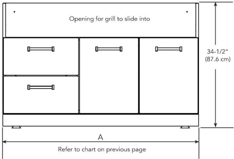
| OVERALL WIDTH (A) | OVERALL HEIGHT | OVERALL DEPTH | |
| VBBO1601 15 5/8" (39.7 cm) 34 1/2" (87.6 cm) 29 7/8" (75.9 cm) | |||
| VBBO2602 26 3/8" (67.0 cm) 34 1/2" (87.6 cm) 29 7/8" (75.9 cm) | |||
| VBBO5160 14 1/2" (36.8 cm) 34 1/2" (87.6 cm) 29 7/8" (75.9 cm) | |||
| VBBO5260 20 1/4" (51.4 cm) 34 1/2" (87.6 cm) 29 7/8" (75.9 cm) | |||
| VBO1811, including doors 18" (45.7 cm) 34 1/2" (87.6 cm) 29 7/8" (75.9 cm) | |||
| VTPO1810, including doors 18" (45.7 cm) 34 1/2" (87.6 cm) 29 7/8" (75.9 cm) | |||
| VBO1830, including doors 18" (45.7 cm) 34 1/2" (87.6 cm) 29 7/8" (75.9 cm) | |||
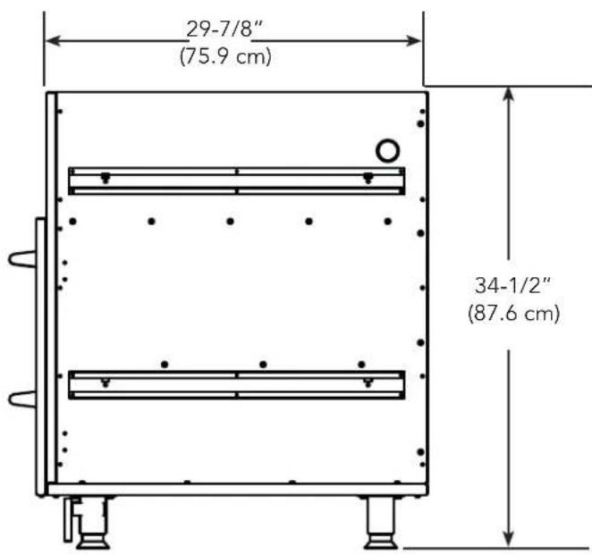
| VSBO2402, including doors 24" (61.0 cm) 34 1/2" (87.6 cm) 29 7/8" (75.9 cm) | |||
| VQBO4121, VQWO4120 41 7/8" (106.4 cm) 34 1/2" (87.6 cm) 29 7/8" (75.9 cm) | |||
| VQBO5322, VQWO5311 53 7/8" (136.8 cm) 34 1/2" (87.6 cm) 29 7/8" (75.9 cm) | |||
| VQBO5420 42 1/4" (107.3 cm) 34 1/2" (87.6 cm) 29 7/8" (75.9 cm) | |||
| VQBO5540 54 1/4" (137.8 cm) 34 1/2" (87.6 cm) 29 7/8" (75.9 cm) | |||
| VURO3200 32" (81.3 cm) 34 1/2" (87.6 cm) 29 7/8" (75.9 cm) | |||
| VBPFLR4 4" (10.2 cm) 34 1/2" (87.6 cm)* 3/4" (1.9 cm) | |||
| VFLR4 4" (10.2 cm) 34 1/2" (87.6 cm)* 3/4" (1.9 cm) | |||
| VBFLR8 | 8" (20.3 cm) 34 1/2" (87.6 cm)* 3/4" (1.9 cm) | ||
| VFLR8 8" (20.3 cm) 34 1/2" (87.6 cm)* 3/4" (1.9 cm) | |||
| VSP30 29 7/8" (75.9 cm) 34 1/2" (87.6 cm)* 0" | |||
| VCF90 | 3" (7.6 cm)** | 34" (86.4 cm)* | 3/4" (1.9 cm) |
| VOCF90 | 33" (83.8 cm)** | 34 1/2" (87.6 cm)* | 3/4" (1.9 cm) |
| VCF135 | 3" (7.6 cm)** | 34 1/2" (87.6 cm)* | 3/4" (1.9 cm) |
| VOCF135 | 15 1/2" (39.4 cm)** | 34 1/2" (87.6 cm)* | 3/4" (1.9 cm) |
| VBP16 | 16" (40.6 cm) 34 1/2" (87.6 cm)* | 3/4" (1.9 cm) | |
| VBP18 | 18" (45.7 cm) 34 1/2" (87.6 cm)* | 3/4" (1.9 cm) | |
| VBP24 | 24" (61.0 cm) 34 1/2" (87.6 cm)* | 3/4" (1.9 cm) | |
| VBP26 | 26 3/8" (67.0 cm) | 34 1/2" (87.6 cm)* | 3/4" (1.9 cm) |
| VBP32 | 32" (81.3 cm) 34 1/2" (87.6 cm)* | 3/4" (1.9 cm) | |
| VBP41 | 41 7/8" (106.4 cm) | 34 1/2" (87.6 cm)* | 3/4" (1.9 cm) |
| VBP53 | 53 7/8" (136.8 cm) | 34 1/2" (87.6 cm)* | 3/4" (1.9 cm) |
| VBP14SS | 14 1/4"(36.2 cm) | 30 3/4" (78.1 cm) | 3/4" (1.9 cm) |
| VBP20SS | 20 1/4" (51.4 cm) 30 3/4" (78.1 cm) | 3/4" (1.9 cm) | |
| VBP42SS | 42 1/4" (107.3 cm) 30 3/4" (78.1 cm) | 3/4" (1.9 cm) | |
| VPB54SS | 54 1/4" (137.8 cm) 30 3/4" (78.1 cm) | 3/4" (1.9 cm) |
*includes provided toe kick
**from inside of turn to next cabinet
Front View
Side View
SERVICE INFORMATION
If service is required, call your authorized service agency.
Have the following information readily available:
- Model number
- Serial number
- Date purchased
• Name of dealer from whom purchased
Clearly describe the problem that you are having. If you are unable to obtain the name of an authorized service agency, or if you continue to have service problems, contact Viking Range at (888) 845-4641 or write to:
VIKING RANGE, LLC
PREFERRED SERVICE
111 Front Street
Greenwood, Mississippi 38930 USA
Record the information indicated below. You will need it if service is ever required.
Model No. ____
Serial No. ____
Date of Purchase
Date Installed
Dealer's Name
Address
If service requires installation of parts, use only authorized parts to insure protection under the warranty.
Keep this manual for future reference.
PROFESSIONAL SERIES OUTDOOR STAINLESS STEEL WARRANTY TWO YEAR FULL WARRANTY
Outdoor cabinets and all of their component parts, except as detailed below*, are warranted to be free from defective materials or workmanship in normal residential use for a period of two (2) years from the date of original retail purchase or closing date for new construction, whichever period is longer.. Viking Range, LLC, warrantor, agrees to repair or replace, at its option, any part which fails or is found to be defective during the warranty period.
*FULL NINETY (90) DAY COSMETIC WARRANTY: Decorative items are warranted to be free from defective materials or workmanship (such as scratches on stainless steel, etc.) for a period of ninety (90) days from the date of original retail purchase. ANY DEFECTS MUST BE REPORTED TO THE SELLING DEALER WITHIN NINETY (90) DAYS FROM DATE OF ORIGINAL RETAIL PURCHASE. Viking Range, LLC uses the most up-to-date processes and best materials available to produce all finishes. However, slight color variation may be noticed because of the inherent differences in lighting, product locations, and other factors. Therefore, this warranty does not apply to variations attributable to such factors.
TWO YEAR FULL WARRANTY
Any door hinges or drawer slides which fail due to defective materials or workmanship in normal household use during the second year from the date of original retail purchase will be repaired or replaced, free of charge for the part itself, with the owner paying all other costs, including labor.
This warranty extends to the original purchaser of the product warranted hereunder and to each transferee owner of the product during the term of the warranty.
TERMS AND CONDITIONS
This warranty extends to the original purchaser of the product warranted hereunder and to each transferee owner of the product during the term of the warranty and applies to products purchased and located in the United States and Canada. Products must be purchased in the country where service is requested. If the product or one of its component parts contains a defect or malfunction during the full warranty period after a reasonable number of attempts by the warrantor to remedy the defect or malfunction, the owner is entitled to either a refund or replacement of the product or its component part or parts. Replacement of a component part includes its free installation, except as specified under the limited warranty. Under the terms of this warranty, service must be performed by a factory authorized Viking Range, LLC service agent or representative. Service will be provided during normal business hours, and labor performed at overtime or premium rates shall not be covered by this warranty.
Owner shall be responsible for proper installation, providing reasonable and necessary maintenance, providing proof of purchase upon request, and making the appliance reasonably accessible for service. The return of the Owner Registration Card is not a condition of warranty coverage. You should, however, return the Owner Registration Card so that Viking Range, LLC can contact you should any question of safety arise which could affect you. This warranty gives you specific legal rights, and you may also have other rights which may vary from jurisdiction to jurisdiction.
WHAT IS NOT COVERED BY THIS WARRANTY: This warranty shall not apply to damage resulting from abuse, failure to provide reasonable and necessary maintenance, accident, delivery, negligence, natural disaster, loss of electrical power to the product for any reason, alteration, outdoor use, improper installation, improper operation, or repair or service of the product by anyone other than an authorized Viking Range, LLC service agency or representative. This warranty does not apply to commercial usage.
LIMITATION OF REMEDIES AND DURATION OF IMPLIED WARRANTY OWNER'S SOLE AND EXCLUSIVE REMEDY FOR A CLAIM OF ANY KIND WITH RESPECT TO THIS PRODUCT SHALL BE THE REMEDIES SET FORTH ABOVE. VIKING RANGE, LLC IS NOT RESPONSIBLE FOR CONSEQUENTIAL OR INCIDENTAL DAMAGE, INCLUDING BUT NOT LIMITED TO FOOD OR MEDICINE LOSS, DUE TO PRODUCT FAILURE, WHETHER ARISING OUT OF BREACH OF WARRANTY, BREACH OF CONTRACT OR OTHERWISE. Some jurisdictions do not allow the exclusion or limitation of incidental or consequential damages, so the above limitation or exclusions may not apply to you. ANY IMPLIED WARRANTIES OF MERCHANTABILITY OR FITNESS FOR A PARTICULAR PURPOSE APPLICABLE TO THIS PRODUCT ARE LIMITED IN DURATION TO THE PERIOD OF COVERAGE OF THE APPLICABLE EXPRESS WRITTEN LIMITED WARRANTIES SET FORTH ABOVE. Some states do not allow limitations on how long an implied warranty lasts, so the above limitation may not apply to you.
WARRANTY SERVICE: To obtain warranty service, contact an authorized Viking Range, LLC service agent, or Viking Range, LLC, 111 Front Street, Greenwood, Mississippi 38930, (888) 845-4641. Provide model and serial number and date of original purchase or closing date for a new construction. For the name of your nearest authorized Viking Range, LLC service agency, call Viking Range, LLC. IMPORTANT: Retain proof of original purchase to establish warranty period.
Specifications subject to change without notice.
Viking Range, LLC
111 Front Street
Greenwood, Mississippi 38930 USA
(662) 455-1200
For product information,
call 1-888-(845-4641)
or visit the Viking Web site at vikingrange.com
068259-000 EN (051018)
natural_image
Exterior view of a stainless steel VIKING 3000 air fryer with open doors and control knobs (no visible text or symbols)natural_image
Line drawing of a 3D box with drawers and handle, labeled 'l'illustration 1' (no other text or symbols)l'illustration 2
natural_image
Technical line drawing of a two-panel industrial enclosure with ventilation fixtures (no text or symbols)IMPORTANT : VEUILLEZ LIRE ET APPLIQUER
natural_image
Line drawing of a simple cabinet with two drawers and a lid (no text or symbols)| LARGEUR TOTALE HAUTEUR TOTALE PROFONDEUR | ||
| TOTALE | ||
| VBBO1601 15 5/8" 939,7 cm) 34 1/2" (87.6 cm) 29 7/8" (75.9 cm) | ||
| VBBO2602 26 3/8" (67.0 cm) 34 1/2" (87.6 cm) 29 7/8" (75.9 cm) | ||
| VBBO5160 14 1/2" (36.8 cm) 34 1/2" (87.6 cm) 29 7/8" (75.9 cm) | ||
| VBBO5260 20 1/4" (51.4 cm) 34 1/2" (87.6 cm) 29 7/8" (75.9 cm) | ||
| VBO1811, including doors 18" (45.7 cm) 34 1/2" (87.6 cm) 29 7/8" (75.9 cm) | ||
| VTPO1810, including doors 18" (45.7 cm) 34 1/2" (87.6 cm) 29 7/8" (75.9 cm) | ||
| VBO1830, including doors 18" (45.7 cm) 34 1/2" (87.6 cm) 29 7/8" (75.9 cm) | ||
| VSBO2402, including doors 24" (61.0 cm) 34 1/2" (87.6 cm) 29 7/8" (75.9 cm) | ||
| VQBO4121, VQWO4120 41 7/8" (106.4 cm) 34 1/2" (87.6 cm) 29 7/8" (75.9 cm) | ||
| VQBO5322, VQWO5311 53 7/8" (136.8 cm) 34 1/2" (87.6 cm) 29 7/8" (75.9 cm) | ||
| VQBO5420 42 1/4" (107.3 cm) 34 1/2" (87.6 cm) 29 7/8" (75.9 cm) | ||
| VQBO5540 54 1/4" (137.8 cm) 34 1/2" (87.6 cm) 29 7/8" (75.9 cm) | ||
| VURO3200 32" (81.3 cm) 34 1/2" (87.6 cm) 29 7/8" (75.9 cm) | ||
| VBPFLR4 4" (10.2 cm) 34 1/2" (87.6 cm)* 3/4" (1.9 cm) | ||
| VFLR4 | 4" (10.2 cm) | 34 1/2" (87.6 cm)* |
| VBFLR8 | 8" (20.3 cm) | 34 1/2" (87.6 cm)* |
| VFLR8 | 8" (20.3 cm) | 34 1/2" (87.6 cm)* |
| VSP30 29 7/8" (75.9 cm) 34 1/2" (87.6 cm)* 0" | ||
| VCF90 | 3" (7.6 cm)** | 34" (86.4 cm)* |
| VOCF90 | 33" (83.8 cm)** | 34 1/2" (87.6 cm)* |
| VCF135 | 3" (7.6 cm)** | 34 1/2" (87.6 cm)* |
| VOCF135 | 15 1/2" (39.4 cm)** | 34 1/2" (87.6 cm)* |
| VBP16 | 16" (40.6 cm) | 34 1/2" (87.6 cm)* |
| VBP18 | 18" (45.7 cm) | 34 1/2" (87.6 cm)* |
| VBP24 | 24" (61.0 cm) | 34 1/2" (87.6 cm)* |
| VBP26 | 26 3/8" (67.0 cm) | 34 1/2" (87.6 cm)* |
| VBP32 | 32" (81.3 cm) | 34 1/2" (87.6 cm)* |
| VBP41 | 41 7/8" (106.4 cm) | 34 1/2" (87.6 cm)* |
| VBP53 | 53 7/8" (136.8 cm) | 34 1/2" (87.6 cm)* |
INFORMATIONS SUR L'ENTRETIEN
natural_image
Exterior view of a stainless steel UK-style cooktop appliance with multiple side outlets and control knobs (no visible text or symbols)natural_image
Line drawing of a 3D box-like cabinet with handle and wheels, showing internal compartments and a curved arrow indicating rotation (no text or symbols)llustración #2
natural_image
Pure technical line drawing of a mechanical or architectural component with no text, numbers, or symbolsIMPORTANTE - POR FAVOR LEA Y CUMPLA
natural_image
Technical line drawing of two mechanical components with directional arrows indicating motion or force vectors (no text or symbols present)natural_image
Line drawing of a simple cabinet with two drawers and a lid (no text or symbols)| ANCHO TOTAL ALTURA TOTAL PROFUNDIDAD TOTAL | |||
| VBBO1601 15 5/8" 939.7 cm) 34 1/2" (87.6 cm) | 29 7/8" (75.9 cm) | ||
| VBBO2602 26 3/8" (67.0 cm) 34 1/2" (87.6 cm) | 29 7/8" (75.9 cm) | ||
| VBBO5160 14 1/2" (36.8 cm) 34 1/2" (87.6 cm) | 29 7/8" (75.9 cm) | ||
| VBBO5260 20 1/4" (51.4 cm) 34 1/2" (87.6 cm) | 29 7/8" (75.9 cm) | ||
| VBO1811, incluyendo puertas 18" (45.7 cm) | 34 1/2" (87.6 cm) 29 7/8" (75.9 cm) | ||
| VTPO1810, incluyendo puertas 18" (45.7 cm) | 34 1/2" (87.6 cm) 29 7/8" (75.9 cm) | ||
| VBO1830, incluyendo puertas 18" (45.7 cm) | 34 1/2" (87.6 cm) 29 7/8" (75.9 cm) | ||
| VSBO2402, incluyendo puertas 24" (61.0 cm) | 34 1/2" (87.6 cm) 29 7/8" (75.9 cm) | ||
| VQBO4121, VQWO4120 41 7/8" (106.4 cm) | 34 1/2" (87.6 cm) 29 7/8" (75.9 cm) | ||
| VQBO5322, VQWO5311 53 7/8" (136.8 cm) | 34 1/2" (87.6 cm) 29 7/8" (75.9 cm) | ||
| VQBO5420 42 1/4" (107.3 cm) 34 1/2" (87.6 cm) | 29 7/8" (75.9 cm) | ||
| VQBO5540 54 1/4" (137.8 cm) 34 1/2" (87.6 cm) | 29 7/8" (75.9 cm) | ||
| VURO3200 32" (81.3 cm) 34 1/2" (87.6 cm) | 29 7/8" (75.9 cm) | ||
| VBPFLR4 | 4" (10.2 cm) | 34 1/2" (87.6 cm)* | 3/4" (1.9 cm) |
| VFLR4 | 4" (10.2 cm) | 34 1/2" (87.6 cm)* | 3/4" (1.9 cm) |
| VBFLR8 | 8" (20.3 cm) | 34 1/2" (87.6 cm)* | 3/4" (1.9 cm) |
| VFLR8 | 8" (20.3 cm) | 34 1/2" (87.6 cm)* | 3/4" (1.9 cm) |
| VSP30 | 29 7/8" (75.9 cm) | 34 1/2 " (87.6 cm)* | 0" |
| VCF90 | 3" (7.6 cm)** | 34" (86.4 cm)* | 3/4" (1.9 cm) |
| VOCF90 | 33" (83.8 cm)** | 34 1/2 " (87.6 cm)* | 3/4" (1.9 cm) |
| VCF135 | 3" (7.6 cm)** 34 1/2 " (87.6 cm)* | 3/4" (1.9 cm) | |
| VOCF135 | 15 1/2" (39.4 cm)** | 34 1/2 " (87.6 cm)* | 3/4" (1.9 cm) |
| VBP16 | 16" (40.6 cm) | 34 1/2 " (87.6 cm)* | 3/4" (1.9 cm) |
| VBP18 | 18" (45.7 cm) | 34 1/2 " (87.6 cm)* | 3/4" (1.9 cm) |
| VBP24 | 24" (61.0 cm) | 34 1/2 " (87.6 cm)* | 3/4" (1.9 cm) |
| VBP26 | 26 3/8" (67.0 cm) | 34 1/2 " (87.6 cm)* | 3/4" (1.9 cm) |
| VBP32 | 32" (81.3 cm) | 34 1/2 " (87.6 cm)* | 3/4" (1.9 cm) |
| VBP41 | 41 7/8" (106.4 cm) | 34 1/2 " (87.6 cm)* | 3/4" (1.9 cm) |
| VBP53 | 53 7/8" (136.8 cm) | 34 1/2 " (87.6 cm)* | 3/4" (1.9 cm) |