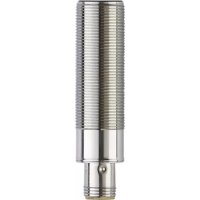
DTM424 - RFID system IFM - Free user manual and instructions
Find the device manual for free DTM424 IFM in PDF.


User questions about DTM424 IFM
0 question about this device. Answer the ones you know or ask your own.
Ask a new question about this device
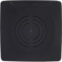
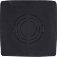
Download the instructions for your RFID system in PDF format for free! Find your manual DTM424 - IFM and take your electronic device back in hand. On this page are published all the documents necessary for the use of your device. DTM424 by IFM.
USER MANUAL DTM424 IFM
Operating instructions
CANopen interface
RF-identification system
DTM424
DTM425
Read/write head
Contents
1 Preliminary note 4
1.1 Symbols used 4
1.2 Warnings.... 4
1.3 Legal and copyright information 4
1.4 Open source information.... 4
2 Safety instructions.... 5
2.1 Safety symbols on the unit 5
2.2 Safety note on high-frequency electromagnetic radiation 5
2.3 Cybersecurity 6
3 Intended use.... 7
3.1 Application area 7
4 Items supplied.... 8
5 Function 9
5.1 ID tags 9
5.2 Device overview 9
6 Installation.... 10
6.1 Notes on the unit installation 10
6.2 Avoiding interference 10
6.3 Mechanical design 10
6.4 Install device.... 11
6.5 Mounting distances.... 11
6.6 Positioning of the ID tags 12
7 Electrical connection.... 14
7.1 Wiring 14
8 Operating and display elements 15
9 Operation 16
9.1 CANopen interface 16
9.1.1 CANopen functions.... 16
9.1.2 Change the Node ID and bit rate.... 16
9.1.3 Set-up 17
9.1.4 Use of 32 bit data types 18
9.1.5 Communication types of the process data object (PDO) 18
9.1.6 Object directory (OD) 18
9.1.7 Error messages.... 24
9.1.8 Monitoring activity via Heartbeat 26
9.1.9 Change objects 26
9.1.10 Process data objects.... 26
9.1.11 Device status 27
9.1.12 Deactivate antenna 29
9.1.13 Select the ID tag type 29
9.1.14 Read information of an ID tag 30
9.1.15 RSSI value 30
9.1.16 ID tag detection filter 30
9.2 Data transfer with an ID tag. 31
9.2.1 Read UID of the ID tag 31
9.2.2 Read data from the ID tag via PDO transfer 31
9.2.2.1 Example 1.... 32
9.2.2.2 Example 2.... 32
9.2.3 Write data to the ID tag via PDO transfer 33
9.2.3.1 Example 1.... 33
9.2.3.2 Example 2.... 34
9.2.4 Error handling for PDO transfer.... 34
9.2.5 Read data from the ID tag via SDO transfer 35
9.2.5.1 Example 35
9.2.6 Write data to the ID tag via SDO transfer 35
9.2.6.1 Example 35
9.2.7 Lock data range on the ID tag via SDO transfer 35
9.2.7.1 Example 36
9.2.8 Error codes during SDO transfer.... 36
9.3 EDS file.... 37
10 Maintenance, repair and disposal 38
11 Approvals/standards 39
Glossary 40
1 Preliminary note
You will find instructions, technical data, approvals and further information using the QR code on the unit / packaging or at documentation.ifm.com.
1.1 Symbols used
√ Requirement
Instructions
Reaction, result
[...] Designation of keys, buttons or indications
→ Cross-reference

Important note
Non-compliance may result in malfunction or interference.

Information
Supplementary note
1.2 Warnings
Warnings indicate the possibility of personal injury and damage to property. This enables safe product handling. Warnings are graded as follows:

WARNING
Warning of serious personal injury
▷ If the warning is not observed, fatal and serious injuries are possible.

CAUTION
Warning of minor to moderate personal injury
▷ If the warning is not observed, minor to moderate injuries are possible.
ATTENTION
Warning of damage to property
▷ If the warning is not observed, damage to property is possible.
1.3 Legal and copyright information
© All rights reserved by ifm electronic gmbh. No part of these instructions may be reproduced and used without the consent of ifm electronic gmbh.
All product names, pictures, companies or other brands used on our pages are the property of the respective rights owners.
1.4 Open source information

For more open source information see: documentation.ifm.com.
2 Safety instructions
- The unit described is a subcomponent for integration into a system.
- The system architect is responsible for the safety of the system.
-
The system architect undertakes to perform a risk assessment and to create documentation in accordance with legal and normative requirements to be provided to the operator and user of the system. This documentation must contain all necessary information and safety instructions for the operator, the user and, if applicable, for any service personnel authorised by the architect of the system.
-
Read this document before setting up the product and keep it during the entire service life.
- The product must be suitable for the corresponding applications and environmental conditions without any restrictions.
- Only use the product for its intended purpose (→ Intended use).
- If the operating instructions or the technical data are not adhered to, personal injury and/or damage to property may occur.
- The manufacturer assumes no liability or warranty for any consequences caused by tampering with the product or incorrect use by the operator.
- Installation, electrical connection, set-up, operation and maintenance of the product must be carried out by qualified personnel authorised by the machine operator.
- Protect units and cables against damage.
• Store the product in its original packaging.
2.1 Safety symbols on the unit
The following symbols are used on the device. Observe the instructions in order to avoid hazards:


• Electric supply must correspond to IEC 61010-1, chapter 9.4 - Limited-energy circuit.
• Device of protection class III. Only for operation in SELV/PELV circuits.
2.2 Safety note on high-frequency electromagnetic radiation
Under application-specific conditions, the risk for the user may differ depending on the installation situation and the device settings.
The system architect/operator is required to carry out a hazard analysis and to take appropriate measures for the protection of persons. In particular national regulations also have to be adhered to. Possible protective measures may include guaranteed minimum distances of a user, access controls and user training.

WARNING
Operation of this device can cause radio interference in residential areas.
▷ The device emits high-frequency electromagnetic waves that may interfere with the operation of electronic devices in the vicinity, including pacemakers, hearing aids and defibrillators.
▶ Due to human exposure regulations, a minimum distance of 20 cm must be maintained between the device and persons.
▶ If you have a pacemaker or other implanted medical product, do not use the device without first consulting your doctor or the manufacturer of your medical product. Keep a safe distance between the device and your medical devices and refrain from further use of the device if you observe permanent impairment of your medical product.
2.3 Cybersecurity
Installation
The device is suitable for operation in a secure environment according to IEC 62443-1-1.
The device was designed for operation behind a firewall.
▶ Carry out a risk assessment of the system according to IEC 62443-1-1.
▶ Take measures to ensure physical security.
Operation
▶ Observe the security functions described in the product documentation and the recommendations for their use.
Maintenance
▶ Regularly check whether software updates are available for the device.
- ▶ Back up system configuration and system data in accordance with your company's change management processes.
Decommissioning
▶ Ensure that no sensitive information can fall into unauthorised hands.
▶ Always reset the system settings to the factory settings before decommissioning the device.
3 Intended use
The read/write head reads and writes ID tags without contact.
The data is made available as process data via the CAN bus interface.
3.1 Application area
The device safety is rated for use under the following operating conditions:
- Protection class 3 (SELV/PELV) and supply of the device to limited energy according to IEC 61010-1, chapter 9.4. Isolate the external circuits as shown in figure 102 in IEC 61010-2-201.
- Indoor and outdoor use.
• Altitudes up to 2000 m. - Relative air humidity up to max. 80 %, non condensing.
- Pollution degree 2.
4 Items supplied
- Read/write head

The device is supplied without installation and connection accessories.
Available accessories: www.ifm.com.
The optimum function is not ensured when using components from other manufacturers.
5 Function
5.1 ID tags
The ID tags are passively operated without a battery. The energy required for operation is provided by the read/write head.
The energy is provided via an inductive coupling. The integrated antenna coil in the read/write head generates a magnetic field which partly penetrates the antenna coil of the ID tag. A voltage is generated by induction that supplies the data carrier with energy.
The device supports ID tags according to ISO 15693.
5.2 Device overview
DTM424
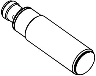 | Article number: | DTM424 |
| Function: | Read/write head | |
| Type designation: | DTMHF GBRWCOUS03 | |
| Type: | M18, flush mountable |
DTM425
 | Article number: | DTM425 |
| Function: | Read/write head | |
| Type designation: | DTMHF GNRWCOUS03 | |
| Type: | M18, non flush mountable |
6 Installation
6.1 Notes on the unit installation
When mounting several RFID units adhere to the minimum distances between the systems.
Flush mounting of a read/write head in metal reduces the read/write distance.
Device performance can be affected if positioned in the immediate vicinity of powerful HF emission sources such as welding transformers or converters.
6.2 Avoiding interference
The device generates a modulated electrical field with a frequency of 13.56 MHz.
Avoid interference with data communication:
▶ Do not operate any devices in the vicinity that use the same frequency band.
▷ Such devices are for example frequency converters and switched-mode power supplies.
If there are other devices in the same frequency band in the vicinity:
▶ The mounting distances between the devices should be as large as possible.
▶ Use the devices in alternating operation.
▶ Switch the HF field of the device on/off.
6.3 Mechanical design
DTM424

Fig. 1: DTM424
1 Sensing face
DTM425

Fig. 2: DTM425
1 Sensing face
6.4 Install device
▶ Fix the device using the supplied nuts (M18).
DTM424
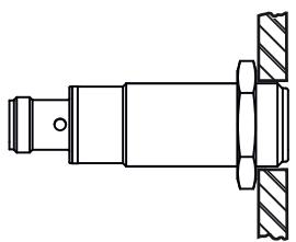
Fig. 3: Flush mounting
DTM425

Fig. 4: Non-flush mounting
6.5 Mounting distances
DTM424

| Operating mode | Distance side (A) | Distance front (B) |
| For reading and writing | ≥ 50 mm | ≥ 100 mm |
DTM425
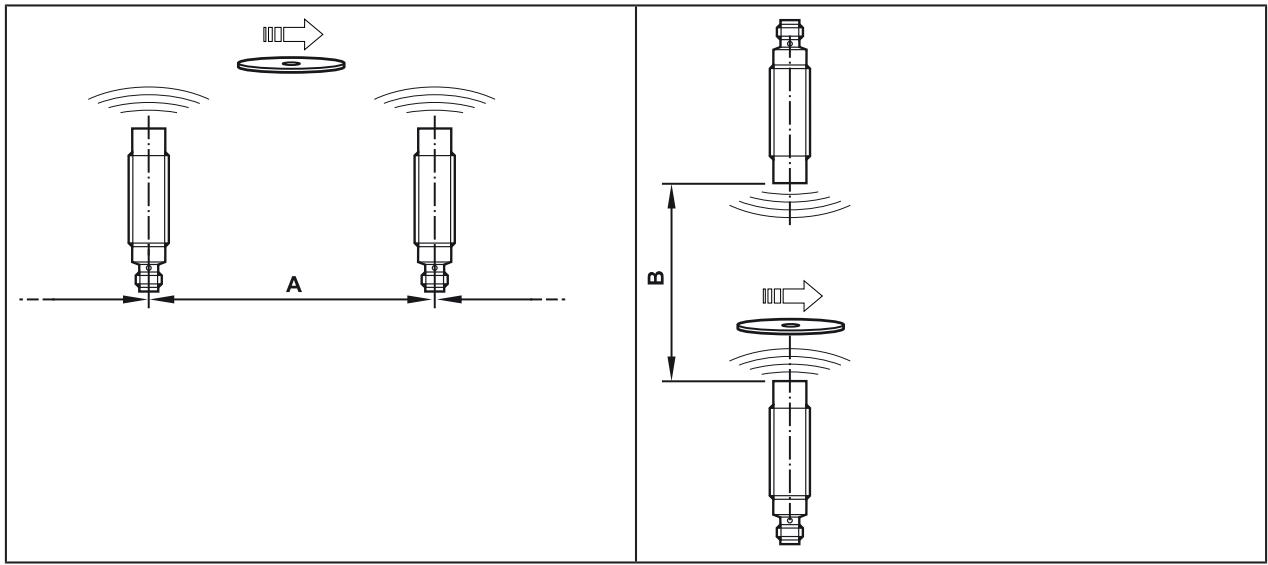
| Operating mode | Distance side (A) | Distance front (B) |
| For reading and writing | ≥ 65 mm | ≥ 180 mm |
6.6 Positioning of the ID tags
The sensing face marks the centre of the integrated antenna coil of the read/write head. ▶ Align the sensing face of the read/write head and the ID tag in the same way.
For installation in or on metal use the ID tags provided for this purpose.
Position the ID tag in the area of the sensing face. When doing so, the angle of aperture and the operating distance must be adhered to ( → Data sheet of the device).
DTM424

Fig. 5: Position the ID tag
▶ Align the ID tag on the central axis of the antenna of the device.
The distance "D" is indicated in the data sheet.
DTM425

Fig. 6: Position the ID tag
▶ Align the ID tag on the central axis of the antenna of the device.
The distance "D" is indicated in the data sheet.
7 Electrical connection

The device must be connected by a qualified electrician.
Device of protection class III (PC III).
The electrical supply must only be made via PELV/SELV circuits.
▶ Disconnect power before connecting the device.
7.1 Wiring
▶ Connect the device to the CAN bus using the M12 connector.
▷ Voltage is supplied via the CAN bus.
| Pin assignment | Wiring |
| M12 connector, A-coded, 5 poles | |
| 1: Shield2: U+3: GND4: CAN high5: CAN low | |

The CAN bus connection is almost trouble-free if the following points are considered:
▶ Use cables approved for CAN bus.
▶ Terminate the cables with 120 Ω terminating resistors.

Information on available sockets see: www.ifm.com.
8 Operating and display elements
| DTM424 | DTM425 |
 | 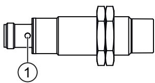 |
1 LEDs green / yellow / red
| LED | State | Description |
| green | on | Operating status pre-operational |
| flashes every 1.6 s alternating with yellow LED | Operating status pre-operational and ID tag detected | |
| flashes every 0.4 s | Operating status operational | |
| yellow | on | Operating status operational and ID tag detected |
| flashes every 1.6 s alternating with green LED | Operating status pre-operational and ID tag detected | |
| flashes | Device hardware fault | |
| red | flashes every 0.4 s alternating with other LED colours | Configuration error |
| flashes every 1.2 s alternating with other LED colours | Error in the CAN bus network | |
| on | CAN bus not accessible | |
| flashes | LSS service active |
9 Operation
9.1 CANopen interface
The read/write head has a standardised CANopen interface according to CiA DS-301. All measured values and parameters can be accessed via the object directory (OD). The individual configuration can be saved in the internal permanent memory.
The device is delivered with node ID 32 and a bit rate of 125 Kbits/s.

▶ Only use cables approved for CANopen.
▶ Terminate the cables using terminating resistors (120 Ω).
▷ The ifm cable EVC492 contains integrated terminating resistors.
9.1.1 CANopen functions
The following CANopen functions are available:
- 64 transmit and receive process data objects (TPDO1.. 64, RPDO1.. 64) in two possible operating modes:
– individual check via remote transmission request telegram (RTR)
– event-controlled transmission
- Error messages via emergency object (EMCY) with support of the:
– general error register
– manufacturer-specific status register
- error list
• Heartbeat monitoring mechanism
• Status and error indication via LED
- In addition to the CiA DS-301 functionality there are more manufacturer and profile-specific characteristics:
- setting of the Node ID and the bit rate via object directory entry (SDO)
- configuration and reading/writing of operational data via service data objects (SDO)
• Support of the layer settings service (LSS)
• Support of synchronous process data transmission (SYNC)
9.1.2 Change the Node ID and bit rate
The device supports several options how to change the Node ID and the bit rate. The device is delivered with the Node ID 32 and a bit rate of 125 Kbits/s.

Each Node ID must only be assigned once in the CANopen network. If a Node ID is assigned several times, malfunction in the CANopen network will result.
Change the Node ID and bit rate in the object directory
The Node ID is entered in the object directory in the objects 0x20F0 and 0x20F1. If the two values are identical, the setting is stored and is active after a software reset of the device. Values between 1 and 127 may be used as Node ID.
The bit rate is entered in the objects 0x20F2 and 0x20F3. If the two values are identical, the setting is stored and is active after a software reset of the device. The following values may be used as bit rate:
| Value | Bit rate |
| 0 | 1000 kBits/s |
| 1 | 800 kBits/s |
| 2 | 500 kBits/s |
| 3 | 250 kBits/s |
| 4 | 125 kBits/s |
| 5 | 100 kBits/s |
| 6 | 50 kBits/s |
| 7 | 20 kBits/s |
If a master is used in the CANopen network for central storage of parameters, the changed values for Node ID (0x20F0 and 0x20F1) and bit rate (0x20F2 and 0x20F3) must be additionally entered in the master.
Otherwise the values will be reset during each start of the CANopen network.
Change the Node ID and bit rate via LSS
Using the layer setting service (LSS) an LSS master can change the Node ID and bit rate of the device (LSS slave) via the CAN bus. The LSS master sets all LSS slaves to a configuration mode. Each LSS slave can be unambiguously identified via the device data (vendor ID, product code, revision number and serial number).
To change the bit rate the LSS master transfers the new bit rate in the configuration mode with the service "Configure timing bit". The LSS slave replies to the LSS master if the new bit rate is supported. Then the LSS master transmits the time "Switch delay" via the service "Activate bit timing" after which the new bit rate should be activated. After activation the LSS master switches the LSS slave again to the operating mode.
To change the Node ID the LSS master transfers the new Node ID in the configuration mode. The LSS slave replies to the master if the new Node ID is valid. After changing the Node ID the LSS master switches the LSS slave again to the operating mode.
The new bit rate and Node ID become active after a software reset of the LSS slave.
9.1.3 Set-up
The CANopen standard CiA301 defines three possible operating states:
Pre-operational
In the pre-operational state no PDO messages (process data) can be transmitted. The pre-operational state is used to set the sensor parameters or as standby mode.
During booting in the pre-operational mode, the device reports the bootUP message "0x700+Node ID" to the CAN bus.
Operational
In the operational state all communication services are carried out. The operational state is used to exchange the process data while in operation.
Stopped
In the stopped state only NMT messages (network management) are possible. This allows almost complete separation of redundant or faulty sensors from the bus.
The master or network manager can request the sensor via NMT messages to change the state accordingly.
9.1.4 Use of 32 bit data types
CANopen defines data types with a maximum size of 64 bits (8 bytes). By means of the data type, the user data of ID tags is transmitted efficiently via the CANopen interface. The data type is also used for the default setting of the device and the EDS file.
However, some controllers can only process data types with a maximum width of 32 bits (4 bytes). In order to support all types of controllers, the device offers alternative data objects whose data types are restricted to max. 32 bits. These data objects are marked by the addition “32 bits” in these instructions. Additionally, an EDS file is supplied for use of the data types that is read by the controller software.
By default, the device uses 64-bit data types (e.g. for the preconfigured PDOs). The setting must be adapted to the use of 32-bit data types. The setting can be changed via the controller software, by reading the corresponding EDS file.
9.1.5 Communication types of the process data object (PDO)
The TPDO can be checked at any time by transmitting a remote transmission request telegram (RTR). Otherwise the TPDOs are sent automatically as soon as their value changes (event-driven).
As an option, the CANOpen service "SYNC" can be used (see CiA 301, 7.2.5 Synchronization object (SYNC)). For the synchronised transmission CANopen provides the SYNC object at which the TPDOs are transmitted after every "nth" reception of a SYNC telegram.
A total of 64 TPDOs and 64 RPDOs is available; on delivery only the first 4 of each are active. If the configuration of the CANopen network allows it, the remaining process data objects can also be activated.
In the standard settings, the process data is assigned to the linear address range of the ID tag. The TPDO1 maps e.g. the first 8 bytes of the user data memory of the ID tag.
Reading of the memory and transmission of the data via TPDO is effected automatically as soon as a new ID tag is detected.
Writing of the data to the ID tag is effected in the same way by writing access to the respective RPDO.
Data transfer per process data object is only possible in the "Operational" operating status.
The preset TPDOs and RPDOs are allocated 64-bit data objects. For use of 32-bit controllers, the settings of the PDOs must be adapted.
9.1.6 Object directory (OD)
CANopen communication (CiA 301)
| Index | Subindex | Name(object) | Type | Access | Default value | PDO mapping capability | Save object value |
| 0x1000 | 0x00 | Device type | u32 | ro | 0x00000000 | - | - |
| 0x1001 | 0x00 | Error register | u8 | ro | 0x00 | - | - |
| 0x1003 | 0x010x02 | Pre-defined error field | u32 | ro | 0x00000000 | - | - |
| 0x1005 | 0x00 | COB ID SYNC | u32 | rw | 0x00000000 | - | Yes |
| 0x1008 | 0x00 | Manufacturer device name | vSTR | ro | Article no. of the device | - | - |
| 0x1009 | 0x00 | Manufacturer hardware version | vSTR | ro | Current hard-ware version | - | - |
| 0x100A | 0x00 | Manufacturer software version | vSTR | ro | Current soft-ware version | - | - |
| 0x1010 | 0x01 | Save parameters(save device parameters in non-volatile memory) | u32 | rw | 0x00000000 | - | - |
| 0x1011 | 0x01 | Load default communication parameters | u32 | rw | 0x00000000 | - | - |
| 0x1014 | 0x00 | COB ID EMCY(COB ID emergency message) | u32 | rw | Node ID + 0x80 | - | - |
| 0x1015 | 0x00 | Inhibit time EMCY(inhibit time between EMCY messages) | u16 | rw | 0x0000 | - | Yes |
| 0x1017 | 0x00 | Producer Heartbeat time(time difference between sent heartbeats in ms) | u16 | rw | 0x0000 | - | Yes |
| 0x1018 | 0x01 | Vendor ID | u32 | ro | 0x0069666D | - | - |
| 0x02 | Product code | u32 | ro | Product code of the device version | - | - | |
| 0x03 | Revision number | u32 | ro | Main revision and current software version | - | - | |
| 0x04 | Serial number | u32 | ro | Serial number of the device | - | - | |
| 0x1200 | 0x01 | COB ID client to server | u32 | ro | Node ID + 0x600 | - | - |
| 0x02 | COB ID client to server | u32 | ro | Node ID + 0x580 | - | - | |
| 0x14000x143F | 0x01 | RPDO parameter: COB ID | u32 | rw | Receive process data objects (RPDO)(→ Process data objects □ 26) | - | Yes |
| 0x02 | RPDO parameter: transmission type | u8 | ro | 0xFF | - | Yes | |
| 0x16000x163F | 0x01-0x08 | RPDO mapping | u32 | rw | Receive process data objects (RPDO)(→ Process data objects □ 26) | - | Yes |
| 0x18000x183F | 0x01 | TPDO parameter: COB ID | u32 | rw | Receive process data objects (RPDO)(→ Process data objects □ 26) | - | Yes |
| 0x02 | TPDO parameter: transmission type | u8 | rw | 0xFF | - | Yes | |
| 0x03 | TPDO parameter: inhibit time | u16 | rw | 0x00 | - | Yes | |
| 0x1A000x1A3F | 0x01-0x08 | TPDO mapping | u32 | rw | Receive process data objects (RPDO)(→ Process data objects □ 26) | - | Yes |
Bus configuration
| Index | Subindex | Name (object) | Type | Access | Default value | PDO mapping capability | Save object value |
| 0x20F0 | 0x00 | Node ID setting A (node ID for CAN-open communication) | u8 | rw | 32 | - | Auto-save |
| 0x20F1 | 0x00 | Node ID setting B (node ID for CAN-open communication) | u8 | rw | 32 | - | Auto-save |
| 0x20F2 | 0x00 | Bit rate setting A (CAN bus bit rate) | u8 | rw | 4 | - | Auto-save |
| 0x20F3 | 0x00 | Bit rate setting B (CAN bus bit rate) | u8 | rw | 4 | - | Auto-save |
Status and control of the reader
| Index | Subindex | Name(object) | Type | Access | Default value | PDO mapping capability | Save object value |
| 0x2150 | 0x00 | Device status (device status flags) | u32 | ro | Yes | - | |
| 0x2151 | 0x00 | Antenna active (enable HF front end of the device) | bool | rw | 1 | - | Yes |
| 0x2160 | 0x01-0xFE | Definition ID tag type (name of supported ID tags) | dom | ro | Select the ID tag type ( → ☐ 29) | - | - |
| 0x2161 | 0x00 | Selection ID tag type (value selects ID tag type defined in 0x2160) | u8 | rw | 2 | - | Yes |
| 0x2162 | 0x00 | RSSI | u8 | ro | - | Yes | - |
ID tag information
| Index | Subindex | Name(object) | Type | Access | Default value | PDO mapping capability | Save object value |
| 0x2180 | 0x00 | Current UID (UID of the ID tag in the reading range, PDO mappable) | u64 | ro | 0x000000000 0000000 | Yes |
| 0x2182 | 0x2181 | Index | |||||||||
Read mappable data
| Index | Subindex | Name(object) | Type | Access | Default value | PDO mapping capability | Save object value |
| 0x2200 | 0x01-0x40 | Read start address in the user memory (start of the address range on the ID tag to be read) | u16 | rw | Receive process data objects (RPDO) (→ Process data objects ☐ 26) | - | Yes |
| 0x2201 | 0x01-0x40 | Read length(length of the memory range on the ID tag to be read; max. 8 bytes) | u8 | rw | Receive process data objects (RPDO)(→ Process data objects ☐ 26) | - | Yes |
| 0x220A | 0x01-0x40 | ID tag data (8 bytes of ID tag data, updated when new ID tag enters the reading range) | u64 | ro | Yes | - | |
| 0x220B | 0x01-0x40 | ID tag data (32 bits) (4 bytes of ID tag data, updated when new ID tag enters the reading range) | u32 | ro | Yes | - |
Read data range
| Index | Subindex | Name(object) | Type | Access | Default value | PDO mapping capability | Save object value |
| 0x2280 | 0x00 | Read start of address (start of the address range on the ID tag to be read) | u16 | rw | 0x0000 | - | Yes |
| 0x2281 | 0x00 | Read length (length of the memory range on the ID tag to be read) | u16 | rw | 0x0000 | - | Yes |
| 0x2282 | 0x00 | ID tag data (requested data from the ID tag as configured in objects 0x2280 and 0x2281) | dom | ro | - | - |
Write mappable data
| Index | Subindex | Name(object) | Type | Access | Default value | PDO mapping capability | Save object value |
| 0x2300 | 0x01-0x40 | Write start address (start of the address range on the ID tag to be written) | u16 | rw | Receive process data objects (RPDO) ( → Process data objects 26) | - | Yes |
| 0x2301 | 0x01-0x40 | Write length(length of the memory range on the ID tag to be written; max. 8 bytes) | u8 | rw | Receive process data objects (RPDO)(→ Process data objects ☐ 26) | - | Yes |
| 0x2302 | 0x01-0x40 | Auto-write(activate automatic write access if a new ID tag is detected) | bool | rw | 0 | - | Yes |
| 0x230A | 0x01-0x40 | ID tag data (8 bytes of ID tag data) | u64 | rw | Yes | - | |
| 0x230B | 0x01-0x40 | ID tag data (32 bits) (4 bytes of ID tag data) | u32 | rw | Yes | - | |
| 0x231E | 0x00 | Write trigger (32 bits) upper PDOs | u32 | rw | 0x000000000000000 | Yes | - |
| 0x231F | 0x00 | Write trigger (32 bits) lower PDOs | u32 | rw | 0x000000000000000 | Yes | - |
Write data range
| Index | Subindex | Name(object) | Type | Access | Default value | PDO mapping capability | Save object value |
| 0x2380 | 0x00 | Write start address (start of the address range on the ID tag to be written) | u16 | rw | 0x0000 | - | Yes |
| 0x2381 | 0x00 | Write length (length of the memory range on the ID tag to be written) | u16 | rw | 0x0000 | - | Yes |
| 0x2382 | 0x00 | ID tag data (data to be written to the ID tag as configured in objects 0x2380 and 0x2381) | dom | wo | - | - |
Lock data range
| Index | Subindex | Name (object) | Type | Access | Default value | PDO mapping capability | Save object value |
| 0x2480 | 0x00 | Lock start address (start of the address range on the ID tag to be locked. Must correspond to the ID tag ranges) | u16 | rw | 0x0000 | - | Yes |
| 0x2481 | 0x00 | Lock length (length of the memory range on the ID tag to be locked. Must correspond to the ID tag ranges) | u16 | rw | 0x0000 | - | Yes |
| 0x2481 | 0x00 | Lock trigger (trigger for locking data on the ID tag as configured in objects 0x2480 and 0x2481) | bool | wo | - | - |
UID filter
| Index | Subindex | Name(object) | Type | Access | Default value | PDO mapping capability | Save object value |
| 0x4603 | 0x00 | UID filter depth | s8 | rw | 0x00 | - | Yes |
| 0x4605 | 0x00 | Zero ID filter depth | s8 | rw | 0x02 | - | Yes |
9.1.7 Error messages
The device supports a number of error messages that are sent in the event of a communication, hardware or RFID error. If one of these errors occurs, the error register (OD index 0x1001) and the error field (OD index 0x1003) are updated.
The COB ID of the emergency message can be changed in the object “COB ID EMCY” (OD index 0x1014). By setting bit 31 in this object the emergency messages are deactivated.
The disable time between two emergency messages can be defined via the object 0x1015. The indication is made in steps of 100 µ s.

The COB ID of the emergency messages is preset to 0x80 + Node ID.
| Error message | Error register (0x1001) | Manufacturer error code | Manufacturer error name | Description |
| 0x8210 | 0x11 | Protocol: PDO not processed due to length error. | ||
| 0x8130 | 0x01 | Monitoring: Node guarding or Heartbeat error | ||
| 0x8100 | 0x11 | Monitoring: general communication error when sending "Bus off" | ||
| 0x5000 | 0x81 | 0x01 | Device hardware error (antenna error) | |
| 0x4200 | 0x09 | 0x02 | Device temperature too high | |
| 0xFF00 | 0x81 | 0x01 | RX: ISO_COM-MAND_ER-ROR_NO_RESPONSE | ID tag did not answer. Possibly the ID tag is no longer in the field. |
| 0xFF00 | 0x81 | 0x02 | RX: ISO_COM-MAND_ER-ROR_RX_ERROR | Error while receiving the answer from the ID tag (CRC error, framing error, collision, etc.). |
| 0xFF01 | 0x81 | 0x01 | TX: ISO_COM-MAND_ER-ROR_NO_RESPONSE | ID tag did not answer. Possibly the ID tag is no longer in the field. |
| 0xFF01 | 0x81 | 0x02 | TX: ISO_COM-MAND_ER-ROR_RX_ERROR | Error while sending the answer from the ID tag (CRC error, framing error, collision, etc.). |
| 0xFF02 | 0x81 | 0x01 | ISO_TAG_ER-ROR_COM-MAND_NOT_SPECI-FIED | The command is not supported. Possible reason: faulty command. |
| 0xFF02 | 0x81 | 0x02 | ISO_TAG_ER-ROR_COM-MAND_SYNTAX | The command is not detected. Possible reason: Number of sections is too high. Format error. |
| 0xFF02 | 0x81 | 0x03 | ISO_TAG_ER-ROR_OP-TION_NOT_SUP-PORTED | Indicated options are not supported. |
| 0xFF02 | 0x81 | 0x0F | ISO_TAG_ER-ROR_OTHER | Other error. |
| 0xFF02 | 0x81 | 0x10 | ISO_TAG_ER-ROR_BLOCK_NOT_USABLE | The specified section cannot be used (or was not found). |
| 0xFF02 | 0x81 | 0x11 | ISO_TAG_ER-ROR_BLOCK_AL-READY_BLOCKED | The specified section has already been locked and cannot be locked again. |
| 0xFF02 | 0x81 | 0x12 | ISO_TAG_ER-ROR_BLOCK_NOT_UP DATEABLE | The specified section has already been locked and its contents cannot be updated. |
| 0xFF02 | 0x81 | 0x13 | ISO_TAG_ER-ROR_BLOCK_WRITE_VERIFY | The specified section could not be programmed normally (a write verify error occurred). |
| 0xFF02 | 0x81 | 0x14 | ISO_TAG_ER-ROR_BLOCK_LOCK_VERIFY | The specified section could not be locked normally (a lock verify error occurred). |
| 0xFF03 | 0x81 | 0x00 | STATUS_BUFF-ER_OVERFL | Internal buffer overflow. |
9.1.8 Monitoring activity via Heartbeat
By means of the Heartbeat function the activity of a device in the CANopen network can be monitored by the master. The device regularly sends a Heartbeat message containing the device status.
The Heartbeat function is activated by entering a value greater than "0" into the Heartbeat interval time object (OD index 0x1017). The value indicates the time between two Heartbeat signals in milliseconds. The Heartbeat function is deactivated with the value "0".
9.1.9 Change objects
Changes of the objects in the object directory are applied at once. The changes will get lost by a reset. To prevent this the objects have to be saved in the internal permanent memory (flash). All the objects marked in the object directory with "Save object value: yes" are permanently stored in the flash of the device. By writing the command "Save" (65766173h) to save the objects (OD index 1010h/01h) all current objects of the object directory are transferred to the flash memory.
The objects can be reset to factory setting by writing the signature "Load" (64616F6Ch) to the OD index 1011h/01h. After a reset the changes are applied.
Depending on the architecture of the CANopen network the objects can also be stored centrally in a CANopen master. In this case the objects are transferred to the device when the system is started and the locally stored values are overwritten.
Special features of the objects Node ID (OD index 0x20F0 and 0x20F1) and the bit rate (OD index 0x20F2 and 0x20F3):
▶ Changes of the objects are only applied after a reset.
▶ The objects cannot be transferred to the flash via the OD index 1010h/01h.
▶ The objects cannot be reset to the factory setting via the OD index 1011h/01h.
9.1.10 Process data objects
64 transmit and receive process data objects each are available. On delivery 4 process data objects are active.
Transmit process data objects (TPDO)
The following table contains the transmit process data objects (TPDO) on delivery.
| TPDO | Settings for PDO mapping: COB | Object directory: Mapped object index | Object directory: Mapped object sub-index | Object directory: Mapped object length | ID tag memory: Read start address | ID tag memory: Read length |
| 1 | Node ID + 0x0180 | 0x2150 | 0x00 | 0x20 | Device status | |
| 2 | Node ID + 0x0280 | 0x220A | 0x01 | 0x40 | 0x00000000 | 0x08 |
| 3 | Node ID + 0x0380 | 0x220A | 0x02 | 0x40 | 0x00000008 | 0x08 |
| 4 | Node ID + 0x0480 | 0x220A | 0x03 | 0x40 | 0x00000010 | 0x08 |
| 5 | 0 (deactivated) | 0x220A | 0x04 | 0x40 | 0x00000018 | 0x08 |
| 64 | 0 (deactivated) | 0x220A | 0x3F | 0x04 | 0x000001F0 | 0x08 |
The preset TPDOs and RPDOs are allocated 64-bit data objects. For use of 32-bit controllers, the settings of the TPDOs and RPDOs must be adapted.
Receive process data objects (RPDO)
The following table contains the receive process data objects (RPDO) on delivery.
| RPDO | Settings for PDO mapping: COB | Object directory: Mapped object index | Object directory: Mapped object sub-index | Object directory: Mapped object length | ID tag memory: Write start address | ID tag memory: Write length |
| 1 | Node ID + 0x0200 | 0x230F | 0x00 | 0x40 | Write trigger | |
| 2 | Node ID + 0x0300 | 0x230A | 0x01 | 0x40 | 0x00000000 | 0x08 |
| 3 | Node ID + 0x0400 | 0x230A | 0x02 | 0x40 | 0x00000008 | 0x08 |
| 4 | Node ID + 0x0500 | 0x230A | 0x03 | 0x40 | 0x00000010 | 0x08 |
| 5 | 0 (deactivated) | 0x230A | 0x04 | 0x40 | 0x00000018 | 0x08 |
| 64 | 0 (deactivated) | 0x230A | 0x3F | 0x04 | 0x000001F8 | 0x08 |

The preset TPDOs and RPDOs are allocated 64-bit data objects. For use of 32-bit controllers, the settings of the TPDOs and RPDOs must be adapted.
9.1.11 Device status
The current device status is represented in the object “Device status” (OD index 0x2150, sub-index 0x00). On delivery the object is assigned to TPDO1.
| Bit | 31 | 30 | 29 | 28 | 27 | 26 | 25 | 24 |
| Status | tag_err | |||||||
| Default value | 0 | 0 | 0 | 0 | 0 | 0 | 0 | 0 |
| Bit | 23 | 22 | 21 | 20 | 19 | 18 | 17 | 16 |
| Status | write_err | |||||||
| Default value | 0 | 0 | 0 | 0 | 0 | 0 | 0 | 0 |
| Bit | 15 | 14 | 13 | 12 | 11 | 10 | 9 | 8 |
| Status | read_err | |||||||
| Default value | 0 | 0 | 0 | 0 | 0 | 0 | 0 | 0 |
| Bit | 7 | 6 | 5 | 4 | 3 | 2 | 1 | 0 |
| Status | r | r | buf_ovfl | fr_err | busy | present | ant | pow |
| Default value | 0 | 0 | 0 | 0 | 0 | 0 | 1 | 1 |
| Status | Value | Description | EMCY message |
| powant | 10 | Power enabled (always 1)Antenna deactivated | |
| 1 | Antenna activated | ||
| present | 0 | No ID tag present | |
| 1 | ID tag present | ||
| busy | 0 | Idle | |
| 1 | Read or write access active | ||
| fr_err | 0 | Front end OK | |
| 1 | Front end error detected (hardware problem) | yes | |
| buf_ovfl | 0 | Buffer ok | |
| 1 | Buffer overflow detected | yes | |
| read_err | Error during the last read operation | yes | |
| write_err | Error during the last write operation | yes | |
| tag_err | Error message from ID tag for last operation | yes |
| Read error codes (updated after each read access of the ID tag) | ||
| 0x00 | ISO_COMMAND_ERROR_NO_ERROR | No error, command successfully executed. |
| 0x01 | SO_COMMAND_ERROR_NO_RESPONSE | ID tag did not answer, maybe ID tag is no longer in the field. |
| 0x02 | ISO_COMMAND_ERROR_RX_ERROR | Error while receiving the answer from the ID tag (CRC error, framing error, collision, etc.). |
| Write error codes (updated after each write access of the ID tag) | ||
| 0x00 | ISO_COMMAND_ERROR_NO_ERROR | No error, command successfully executed. |
| 0x01 | SO_COMMAND_ERROR_NO_RESPONSE | ID tag did not answer, maybe ID tag is no longer in the field? |
| 0x02 | ISO_COMMAND_ERROR_RX_ERROR | Error while receiving the answer from the ID tag (CRC error, framing error, collision, etc.). |
| ID tag error codes (updated after read or write access of the ID tag) | ||
| 0x00 | ISO_TAG_ERROR_NO_ERROR | The ID tag does not cause an error. |
| 0x01 | ISO_TAG_ERROR_COMMAND_NOT_SPECIFIED | The specified command is not supported. Example: command code error. |
| 0x02 | ISO_TAG_ERROR_COMMAND_SYN-TAX | The command is not detected. Number of sections is too high. Example: Format error. |
| 0x03 | ISO_TAG_ERROR_OPTION_NOT_SUPPORTED | The indicated options are not supported. |
| 0x0F | ISO_TAG_ERROR_OTHER | Other error. |
| 0x10 | ISO_TAG_ERROR_BLOCK_NOT_US-ABLE | The specified section cannot be used (or was not found). |
| 0x11 | ISO_TAG_ERROR_BLOCK_AL-READY_BLOCKED | The specified section has already been locked and cannot be locked again. |
| 0x12 | ISO_TAG_ERROR_BLOCK_NOT_UPDATEABLE | The specified section has already been locked and its contents cannot be updated. |
| 0x13 | ISO_TAG_ERROR_BLOCK_WRITE_VERIFY | The specified section could not be programmed normally (a write verify error occurred). |
| 0x14 | ISO_TAG_ERROR_BLOCK_LOCK_VERIFY | The specified section could not be locked normally (a lock verify error occurred). |
9.1.12 Deactivate antenna
The antenna in the device can be deactivated if the value 0 is written to the object "Antenna active" (OD index 0x2151). In this case no ID tag is detected any more since the magnetic field of the device is no longer active.
The antenna is reactivated with the value 1. With the object "Antenna active" it is possible to prevent interference between two devices placed next to each other by alternately deactivating the antennas of the two devices.
9.1.13 Select the ID tag type
The device is compatible with several ID tag types. Depending on the size of the user data memory and manufacturer, the ID tags differ in the access to data. Therefore, the device must know which type of ID tag is used in the system.
In object 0x2161, the ID tag type used in the RFID system can be selected. The available ID tag types can be read in the object 0x2180, sub-index 0x01-0xFE.
| ID tag type | Name | Block size [bytes] | Number of blocks |
| 1 | user-defined | ? | ? |
| 2 | I code SLI | 4 | 28 |
| 3 | I code SLI-S | 4 | 40 |
| 4 | I code SLI-L | 4 | 8 |
| 5 | F-MEM 2k | 8 | 250 |
| 6 | F-MEM 232b | 4 | 58 |
| 7 | F-MEM 8k | 32 | 256 |
| 8 | TI_32b | 4 | 8 |
| 9 | TI_256b | 4 | 64 |
| 10 | ST_128b | 4 | 32 |
| 11 | ST_256b | 4 | 64 |
| 12 | ST_8k | 4 | 2048 |
| 13 | I-Code SLIX2 | 4 | 79 |
Via the object 0x2182 0x06 it is possible to poll the ID tag type read by the device. First of all, the detected ID tag type must be read from the object 0x2182 sub-index 0x06 and this value must be entered in the object 0x2161.

ID tag type 2 is preset.

Recognition of the ID tag type is not supported by all ID tags.

The set ID tag type is permanently saved in the device with the "Save Parameter" object.
9.1.14 Read information of an ID tag
The information of an ID tag can be read via the objects 0x2180 to 0x2182. To do so, the ID tag has to be within the detection range of the device.
The objects 0x2180 and 0x2182 are only valid as long as the ID tag is detected. If there is no ID tag within the range, the values of the objects are reset to 0.
The value of the object 0x2182 can be read from the ID tag on request.

Reading of information is not supported by each ID tag type.
9.1.15 RSSI value
The RSSI value (Received Signal Strength, OD index 0x2162) informs about the strength of the received signal that is emitted by the ID tag in front of the device:
"0": no ID tag detected
"1": minimum signal strength
"8": maximum signal strength

The maximum signal strength is only reached with certain device / ID tag combinations.

The signal strength depends on the distance between the ID tag and the active face of the device.

Position changes in the environment, e.g. of metallic objects, can influence the signal strength.
9.1.16 ID tag detection filter
The following situations result in undesired multiple ID tag detection and reading:
• The ID tag is in the limit range.
- The installation conditions have a negative effect on the electromagnetic field of the device.
Thus, the ID tag is not clearly detected which leads to error messages while reading or writing via PDOs. The objects "UID filter depth" and "Zero ID filter depth" allow for error message filtering.

The following values have proven their worth in practice:
▶ "0" to "5" for dynamic applications (rapidly passing ID tags)
▶ ">5" for static applications
| Time [ms] | 0 | 7 | 14 | 21 | 28 | 35 | 42 | 49 | 56 | 63 | 70 | 77 | 84 | 91 | 98 | 105 | 112 | 119 | 126 | 133 |
| ID tag in the field | ● | ● | ● | ● | ● | ● | ● | ● | ● | ● | ||||||||||
| ID tag not in the field | ● | ● | ● | ● | ● | ● | ● | ● | ● | ● |
| UID filter depth: 0, zero ID filter depth: 0 | ||||||||||||||||||||
| ID tag detected | ● | ● | ● | ● | ● | ● | ● | ● | ● | ● | ||||||||||
| ID tag not detected | ● | ● | ● | ● | ● | ● | ● | ● | ● | ● | ||||||||||
| UID filter depth: 5, zero ID filter depth: 0 | ||||||||||||||||||||
| ID tag detected | • | • | ||||||||||||||||||
| ID tag not detected | • | • | • | • | • | • | • | • | • | • | • | • | • | • | • | • | • | • | ||
| UID filter depth: 0, zero ID filter depth: 5 | ||||||||||||||||||||
| ID tag detected | • | • | • | • | • | • | • | • | • | • | • | • | • | • | • | • | • | • | ||
| ID tag not detected | • | • | ||||||||||||||||||
| UID filter depth: 5, zero ID filter depth: 5 | ||||||||||||||||||||
| ID tag detected | • | • | • | • | • | • | • | |||||||||||||
| ID tag not detected | • | • | • | • | • | • | • | • | • | • | • | • | • | |||||||
Object UID filter depth
The "UID filter depth" object (0x4603/0x00) allows for determining the number of successful ID tag detections to be executed by the device. The ID tag will only be considered on the CAN bus as having been detected (ID tag present) once the set number has been reached.
The value "0" deactivates the filter. The values ">0" delay the "ID tag present" bit by 7 ms. Thus a switch-on delay of the ID tag value is generated. The detection in the limit range stabilises as no value will be provided as long as the ID tag has not been steadily detected.
Object zero ID filter depth
The "Zero ID filter depth" object (0x4605/0x00) allows for determining the number of unsuccessful ID tag detections to be executed by the device. The ID tag will no longer be considered on the CAN bus as present (ID tag present) once the set number has been reached.
The value "0" deactivates the filter. The values ">0" delay the reset of the "ID tag present" bit by 7 ms. Thus a switch-off delay of the ID tag value is generated. The detection in the limit range stabilises as no value will be provided as long as the ID tag does not remain steadily undetected.
9.2 Data transfer with an ID tag
9.2.1 Read UID of the ID tag
The UID (Unique Identification Number) of the ID tag is available in object 0x2180 as soon as an ID tag is within the reading range of the device. If no ID tag is available, the value 0x0000000000000000 is entered.
If the object is mapped on a TPDO, transmission is event-controlled as soon as an ID tag enters the reading range or is removed from the reading field.

For 32-bit controllers, the following objects are used instead of object 0x2180: 0x2190 and 0x2191.
9.2.2 Read data from the ID tag via PDO transfer
The transfer of the PDO data from the ID tag is event-controlled. That means that the configured TPDOs are automatically transmitted by the device when the data change. This is the case, for example, when a new ID tag is detected in the detection range of the device. The data is automatically read by the ID tag and transferred by means of the TPDOs via the CAN bus.
The data that was read by the ID tag and assigned to a TPDO is in the objects 0x220A with the sub-indices 0x01-0x40.
Only that data is read by the ID tag that is assigned to a TPDO. Data objects that are not assigned are not updated automatically.
There are two objects for each data object that are used for configuration:
• 0x2200 (read start address),
- 0x2201 (read length) with sub-indices matching the data object.
The start address in the user data area of the ID tag and length of the files to be read are set in the objects.
For 32-bit controllers, the object 0x220B must be used instead of object 0x220A. The maximum data length is restricted to 32-bit data (4 bytes).
If the configured data length is smaller than the data length of the object used (64 bits or 32 bits), the remaining bits are filled with 0.
Max. 64 bits or 32 bits can be transmitted in one TPDO. For the transmission of larger amounts of data, further TPDOs are assigned and the corresponding data objects are configured.
9.2.2.1 Example 1
The data range 0x10 to 0x18 (8 bytes) is to be transferred with the 2nd TPDO.
| TPDO | Settings for PDO mapping: COB | Object directory: Object index | Object directory: Object sub-index | Object directory: Object length |
| 2 | Node ID + 0x0280 | 0x220A | 0x01 | 0x40 |
Object directory
| Index | Sub-index | Name (object) | Value |
| 0x2200 | 0x01 | Read start of the address (start of the address range on the ID tag to be read) | 0x10 |
| 0x2201 | 0x01 | Read length (length of the memory range on the ID tag to be read; max. 8 bytes) | 0x08 |
9.2.2.2 Example 2
The data range 0x44 to 0x48 (4 bytes) is to be transferred with the 6th TPDO.
| TPDO | Settings for PDO mapping: COB | Object directory: Object index | Object directory: Object sub-index | Object directory: Object length |
| 6 | Node ID + 0x0680 | 0x220A | 0x05 | 0x40 |
Object directory
| Index | Sub-index | Name (object) | Value |
| 0x2200 | 0x05 | Read start of the address (start of the address range on the ID tag to be read) | 0x44 |
| 0x2201 | 0x05 | Read length (length of the memory range on the ID tag to be read; max. 8 bytes) | 0x04 |
9.2.3 Write data to the ID tag via PDO transfer
To write data to an ID tag via PDO transfer an RPDO must be assigned to the object 0x230A with a sub-index in the range from 0x01 to 0x40. The address of the ID tag user data range to which the data is to be written is defined in object 0x2300. The subindices of these objects have to be identical.
The ID tag is written to after the data was written to the RPDO and the respective bit was changed in the "Write trigger" object (OD index 0x230F, sub-index 0x00).
| MSB | LSB | ||||||||
| Bit | 63 | 62 | 61 | .. | .. | .. | 2 | 1 | 0 |
| Trigger | tr64 | tr63 | tr62 | .. | .. | .. | tr3 | tr2 | tr1 |
| Default value | 0 | 0 | 0 | 0 | 0 | 0 | 0 | 0 | 0 |
| Trigger | Description |
| tr64 | Trigger for ID tag data 64 (0x230A/0x40) |
| tr63 | Trigger for ID tag data 63 (0x230A/0x3F) |
| tr62 | Trigger for ID tag data 62 (0x230A/0x3E) |
| tr61 | Trigger for ID tag data 61 (0x230A/0x3D) |
| tr60 | Trigger for ID tag data 60 (0x230A/0x3C) |
| tr59 | Trigger for ID tag data 59 (0x230A/0x3B) |
| tr58 | Trigger for ID tag data 58 (0x230A/0x3A) |
| ... | ... |
| tr6 | Trigger for ID tag data 6 (0x230A/0x6) |
| tr5 | Trigger for ID tag data 5 (0x230A/0x5) |
| tr4 | Trigger for ID tag data 4 (0x230A/0x4) |
| tr3 | Trigger for ID tag data 3 (0x230A/0x3) |
| tr2 | Trigger for ID tag data 2 (0x230A/0x2) |
| tr1 | Trigger for ID tag data 1 (0x230A/0x1) |
The writing process is always made with the bit change of the respective bit (0->1 or 1->0). Ideally, the object "Write trigger" (OD index 0x230F, sub-index 0x00) is assigned to an RDPO. On delivery, the object "Write trigger" is assigned to the first RPDO.
Automatic writing of data can be activated with the object "Auto write" (OD index 0x2302). As soon as an ID tag is in the detection range, the last data is written to the ID tag.

Only data up to the configured data length is written to the ID tag. Subsequent data is ignored. For the writing of more than 8 bytes (4 bytes for 32-bit data objects), more RPDOs have to be assigned and the respective data objects have to be configured.

For 32-bit controllers, the object 0x230B must be used instead of object 0x230A. The maximum data length is restricted to 32-bit data (4 bytes).
The trigger is divided between the objects 0x231E and 0x231F. The object 0x231E contains the triggers for ID data 33 to 64. The object 0x231F contains the triggers for ID data 1 to 32.
9.2.3.1 Example 1
The data range 0x10 to 0x18 (8 bytes) is to be transferred with the 2nd RPDO.
| RPDO | Settings for PDO mapping: COB | Object directory: Object index | Object directory: Object sub-index | Object directory: Object length |
| 2 | Node ID + 0x0200 | 0x230A | 0x01 | 0x40 |
Object directory
| Index | Sub-index | Name (object) | Value |
| 0x2300 | 0x01 | Read start of the address (start of the address range on the ID tag to be read) | 0x10 |
| 0x2301 | 0x01 | Read length (length of the memory range on the ID tag to be read; max. 8 bytes) | 0x08 |
| 0x2302 | 0x01 | Auto-write | 0x00 |
Transfer data via RPDO:
| PDO Transmission | PDO | Data |
| To the device | RPDO 2 | 0x12345678 |
Start write access:
| PDO Transmission | PDO | Data |
| To the device | RPDO 1 | Select bit 0 status |
9.2.3.2 Example 2
The data range 0x44 to 0x48 (4 bytes) is to be transferred with the 6th RPDO. In addition, this data is to be written to an ID tag each time it reaches the detection range of the device.
| RPDO | Settings for PDO mapping: COB | Object directory: Object index | Object directory: Object sub-index | Object directory: Object length |
| 6 | Node ID + 0x0600 | 0x230A | 0x05 | 0x40 |
Object directory
| Index | Sub-index | Name (object) | Value |
| 0x2300 | 0x05 | Read start of the address (start of the address range on the ID tag to be read) | 0x44 |
| 0x2301 | 0x05 | Read length (length of the memory range on the ID tag to be read; max. 8 bytes) | 0x04 |
| 0x2302 | 0x05 | Auto-write | 0x01 |
Transfer data via RPDO:
| PDO Transmission | PDO | Data |
| To the device | RPDO 6 | 0x12340000 |
The data is written to the ID tag when it has reached the detection range.

64-bit data (8 bytes) / 32-bit data (4 bytes) always have to be sent to an RPDO. For smaller data lengths than 64 bits / 32 bits, the remaining bits are ignored.
9.2.4 Error handling for PDO transfer
If a read or write access to an ID tag is not possible, the device creates an emergency message on the CAN bus.
The error code can be read from the error register (OD index 0x1001, sub-index 0x00) and the predefined error field (OD index 0x1003, sub-index 0x01-0x02).
9.2.5 Read data from the ID tag via SDO transfer
To read data from an ID tag via SDO transfer it is necessary to define the data address and length on the ID tag. The address must be indicated in object 0x2280 and the data length in object 0x2281.
Then read access can be started from the ID tag via a data transfer to object 0x2282.
9.2.5.1 Example
The data range 0x50 to 0x70 is to be read from the ID tag.
Object directory
| Index | Sub-index | Name (object) | Value |
| 0x2280 | 0x00 | Read start of the address (start of the address range on the ID tag to be read) | 0x50 |
| 0x2281 | 0x00 | Read length (length of the memory range on the ID tag to be read; max. 8 bytes) | 0x20 |
Transfer is started via reading the object 0x2282, sub-index 0x00.

The data is transferred in one piece as domain data type. Up to a data length of 4 bytes transfer is effected as expedited transfer; longer data lengths as segmented transfer.

The recipient must be prepared for temporary storage and processing of the data.
9.2.6 Write data to the ID tag via SDO transfer
To write data to an ID tag via SDO transfer it is necessary to define the data address and length on the ID tag.
The address must be indicated in object 0x2380 and the data length in object 0x2381. Then the write access to the ID tag can be started via a data transfer to object 0x2382.
9.2.6.1 Example
The data range 0x34 to 0x38 is to be transferred to the ID tag.
Object directory
| Index | Sub-index | Name (object) | Value |
| 0x2380 | 0x00 | Write start of the address (start of the address range on the ID tag to be written) | 0x34 |
| 0x2381 | 0x00 | Write length (length of the memory range on the ID tag to be written) | 0x03 |
| 0x2382 | 0x00 | ID tag data (data to be written to the ID tag) | 0x01020304 |

The data is transferred in one piece as domain data type. Up to a data length of 4 bytes transfer is effected as expedited transfer; longer data lengths as segmented transfer.

The transmitter must be able to provide the indicated data length.
9.2.7 Lock data range on the ID tag via SDO transfer
The data ranges of the ID tag can be write-protected.

The write protection of a data range cannot be removed.
The start address of the data range to be protected is stored in the object "Address lock start point" (OD index 0x2480). In addition, the data range length is stored in the object "Write length" (OD index 0x2481).
To activate the write protection, "1" is written on the trigger (OD index 0x2482).

The start address must be identical with the start address of a storage block on the ID tag. The length must be a multiple of the length of a storage block on the ID tag.
9.2.7.1 Example
The data range 0x04 to 0x0C is to be write-protected for an ID tag of block size 4 (2 blocks or 8 bytes).
Object directory
| Index | Subindex | Name (object) | Value |
| 0x2480 | 0x00 | Lock start of the address (start of the address range on the ID tag to be locked) | 0x04 |
| 0x2481 | 0x00 | Write length (length of the memory range on the ID tag to be locked) | 0x08 |
| 0x2482 | 0x00 | ID tag lock trigger | 0x01 |
9.2.8 Error codes during SDO transfer
SDO transfers are acknowledged transfers. If there is an error during transfer or during actions caused by the transfer, an error is signalled after the SDO transfer.
| SDO error code | Description | Possible cause |
| 0x05030000 | Toggle bit unchanged. | |
| 0x05040000 | SDO protocol expired. | |
| 0x05040001 | Client/server command specifier not valid or unknown. | |
| 0x05040002 | Invalid block size (block mode only). | |
| 0x05040003 | Invalid sequence number (block mode only). | |
| 0x05040004 | CRC error (block mode only). | |
| 0x05040005 | Out of memory. | |
| 0x06010000 | Access to the object is not supported. | |
| 0x06010001 | Attempt to read a write only object. | |
| 0x06010002 | Attempt to write a read only object. | |
| 0x06020000 | Object does not exist in the object dictionary. | |
| 0x06040041 | Object cannot be mapped to the PDO. | |
| 0x06040042 | The number and length of the objects to be mapped would exceed PDO length. | |
| 0x06040043 | Reason: general parameter incompatibility. | |
| 0x06040047 | General parameter incompatibility in the device. | |
| 0x06060000 | Access failed due to a hardware error. | |
| 0x06070010 | Data type does not match; length of the service parameter does not match. | |
| 0x06070012 | Data type does not match; service parameter too long. | |
| 0x06070013 | Data type does not match; service parameter too short. | |
| 0x06090011 | Sub-index does not exist. | |
| 0x06090030 | Invalid value for parameter (download only). | |
| 0x06090031 | Value of written parameter is too high (download only). | |
| 0x06090032 | Value of written parameter is too low (download only). | |
| 0x06090036 | Maximum value is lower than minimum value. | |
| 0x060A0023 | Resource not available: SDO connection. | |
| 0x08000000 | General Error. | |
| 0x08000020 | Data cannot be transferred to the application or be stored. | Error read or write access of the ID tag. Detailed information in the device status object (0x2150). |
| 0x08000021 | Data cannot be transferred to the application or be stored due to a local controller. | |
| 0x08000022 | Data cannot be transferred to the application or stored due to the current device status. | |
| 0x08000023 | The dynamic generation of the object directory fails or no object directory is present (e.g. object directory is generated from the file and the generation fails because of a file error). | |
| 0x08000024 | No data available. | Data length = 0 |
9.3 EDS file
The EDS file serves as a template for different configurations of a device type. The EDS file is turned into a DCF file which contains device configurations, object values, Node ID and bit rate.
CANopen configuration tools are available for the configuration of the CANopen network and the devices.
The EDS files are available on ifm's website: www.ifm.com
Contents of the EDS file:
- Communication functions and objects (to CANopen profile DS-301)
• Manufacturer-specific objects

The installation of the EDS file depends on the configuration tool.
▶ Contact the manufacturer of the controller for more information.

▷ The EDS files are supplied with 64-bit or 32-bit data types. The controller determines whether 64-bit or 32-bit data types can be processed.
▶ Select the EDS file appropriate to the controller.
10 Maintenance, repair and disposal
The unit is maintenance-free.
▶ Contact ifm in case of malfunction.
▶ Do not open the housing as the unit does not contain any components which can be maintained by the user. The unit must only be repaired by the manufacturer.
▶ Clean the device using a dry cloth.
▶ Dispose of the unit in accordance with the national environmental regulations.
11 Approvals/standards
For approvals and standards, the following information is available:
• Test standards and regulations: documentation.ifm.com
• EU declaration of conformity and approvals: documentation.ifm.com
• Notes relevant for approval: Package insert of the device and documentation.ifm.com
Glossary
CAN
Controller Area Network, bus system for use in mobile applications.
CANopen
CAN-based network protocol on the application level with an open configuration interface (object directory)
CiA
CAN in Automation e. V., user and manufacturer organisation in Germany/Erlangen, definition and control body for CAN and CAN-based network protocols.
COB
CANopen communication object (PDO, SDO, EMCY, ...)
EDS
Electronic data sheet
EMCY
The emergency object contains an alarm message with which the device signals an error.
Heartbeat
Configurable cyclic monitoring among network participants. In contrast to "node guarding" no superior NMT master is required.
IC reference
The IC reference designates the chip type of the ID tag. It is assigned by the manufacturer of the ID tag.
ID tag
An ID tag is used to identify objects. A read/write device is used to read the ID tag via a high-frequency radio signal. An ID tag consists of an antenna, an analogue circuit for receiving and transmitting (transceiver), a digital circuit and a non-volatile memory.
LSS
Procedure to set basic device settings
NMT
Network management
Node ID
Unambiguous number of a participant in the CANopen network.
Object
Term for data/messages which can be exchanged in the CANopen network.
PDO
The Process Data Object transmits process data in real time in the CANopen network, for example the speed of a motor. PDOs have a higher priority than SDOs; in contrast to the SDOs they are transferred without confirmation. PDOs consist of a CAN message with identifier and up to 8 bytes of user data.
PDO mapping
Describes the application data transferred with a PDO.
RPDO
Process data object received from the device.
RSSI
The Received Signal Strength Indication is the field strength of the received signal.
SDO
The SDO directly accesses the object directory of a network participant (read/write). An SDO can consist of several CAN messages. The transfer of the individual messages is confirmed by the addressed participant. With the SDOs, devices can be configured and parameters can be set.
SYNC
The SYNC telegram initiates the synchronised transmission of process data.
TPDO
Process data object sent by the device.
- 1 PRELIMINARY NOTE
- 1.1 SYMBOLS USED
- 1.2 WARNINGS
- 1.3 LEGAL AND COPYRIGHT INFORMATION
- 1.4 OPEN SOURCE INFORMATION
- 2 SAFETY INSTRUCTIONS
- 2.1 SAFETY SYMBOLS ON THE UNIT
- 2.2 SAFETY NOTE ON HIGH-FREQUENCY ELECTROMAGNETIC RADIATION
- 2.3 CYBERSECURITY
- 3 INTENDED USE
- 3.1 APPLICATION AREA
- 4 ITEMS SUPPLIED
- 5 FUNCTION
- 5.1 ID TAGS
- 5.2 DEVICE OVERVIEW
- 6 INSTALLATION
- 6.1 NOTES ON THE UNIT INSTALLATION
- 6.2 AVOIDING INTERFERENCE
- 6.3 MECHANICAL DESIGN
- 6.4 INSTALL DEVICE
- 6.5 MOUNTING DISTANCES
- 6.6 POSITIONING OF THE ID TAGS
- 7 ELECTRICAL CONNECTION
- 7.1 WIRING
- 8 OPERATING AND DISPLAY ELEMENTS
- 9 OPERATION
- 9.1 CANOPEN INTERFACE
- 9.1.1 CANOPEN FUNCTIONS
- 9.1.2 CHANGE THE NODE ID AND BIT RATE
- 9.1.3 SET-UP
- 9.1.4 USE OF 32 BIT DATA TYPES
- 9.1.5 COMMUNICATION TYPES OF THE PROCESS DATA OBJECT (PDO)
- 9.1.6 OBJECT DIRECTORY (OD)
- 9.1.7 ERROR MESSAGES
- 9.1.8 MONITORING ACTIVITY VIA HEARTBEAT
- 9.1.9 CHANGE OBJECTS
- 9.1.10 PROCESS DATA OBJECTS
- 9.1.11 DEVICE STATUS
- 9.1.12 DEACTIVATE ANTENNA
- 9.1.13 SELECT THE ID TAG TYPE
- 9.1.14 READ INFORMATION OF AN ID TAG
- 9.1.15 RSSI VALUE
- 9.1.16 ID TAG DETECTION FILTER
- 9.2 DATA TRANSFER WITH AN ID TAG
- 9.2.1 READ UID OF THE ID TAG
- 9.2.2 READ DATA FROM THE ID TAG VIA PDO TRANSFER
- 9.2.2.1 EXAMPLE 1
- 9.2.2.2 EXAMPLE 2
- 9.2.3 WRITE DATA TO THE ID TAG VIA PDO TRANSFER
- 9.2.3.1 EXAMPLE 1
- 9.2.3.2 EXAMPLE 2
- 9.2.4 ERROR HANDLING FOR PDO TRANSFER
- 9.2.5 READ DATA FROM THE ID TAG VIA SDO TRANSFER
- 9.2.5.1 EXAMPLE
- 9.2.6 WRITE DATA TO THE ID TAG VIA SDO TRANSFER
- 9.2.6.1 EXAMPLE
- 9.2.7 LOCK DATA RANGE ON THE ID TAG VIA SDO TRANSFER
- 9.2.7.1 EXAMPLE
- 9.2.8 ERROR CODES DURING SDO TRANSFER
- 9.3 EDS FILE
- 10 MAINTENANCE, REPAIR AND DISPOSAL
- 11 APPROVALS/STANDARDS
Brand : IFM
Model : DTM424
Category : RFID system