
Thunder Marine WET75.4 - Receiver MTX Audio - Free user manual and instructions
Find the device manual for free Thunder Marine WET75.4 MTX Audio in PDF.
| Product type | 4-channel marine amplifier |
| Brand | MTX Audio |
| Model | Thunder Marine WET75.4 |
| Output power (RMS) | 4 x 75 W at 4 Ω, 4 x 100 W at 2 Ω |
| Power supply | 12 V DC (vehicle battery) |
| Power consumption | Recommended fuse: 60 A |
| Frequency response | 15 Hz to 25 kHz (full range) |
| High-pass filter (HPF) | 10 Hz to 200 Hz (front), 50 Hz to 750 Hz (rear) |
| Low-pass filter (LPF) | 50 Hz to 750 Hz (rear) |
| Signal-to-noise ratio | > 78 dB |
| Total harmonic distortion | < 0.05% (at 4 Ω, 1 W) |
| Minimum load impedance | 2 Ω per channel |
| Dimensions (H x W x D) | 56.5 x 160 x 310 mm |
| Weight | 2.5 kg (estimated) |
| Enclosure material | Aluminum with plexiglass cover |
| Protection rating | Marine design with conformal coated PCB and rubber gaskets |
| Built-in protections | Short circuit, overvoltage, undervoltage (< 8 V), overheat (80°C) |
| Signal input | 2 pairs RCA (front/rear), sensitivity 0.2 to 5 V |
| Speaker outputs | 4 channels, screw terminals |
| Additional functions | Adjustable gain, subsonic filter (not applicable for this model), bass boost not available |
| Installation | Flat or vertical mounting, ventilation required |
Frequently Asked Questions - Thunder Marine WET75.4 MTX Audio
User questions about Thunder Marine WET75.4 MTX Audio
0 question about this device. Answer the ones you know or ask your own.
Ask a new question about this device
Download the instructions for your Receiver in PDF format for free! Find your manual Thunder Marine WET75.4 - MTX Audio and take your electronic device back in hand. On this page are published all the documents necessary for the use of your device. Thunder Marine WET75.4 by MTX Audio.
USER MANUAL Thunder Marine WET75.4 MTX Audio
OWNER'S MANUAL WET SERIES AMPLIFIERS
PRODUCT INFORMATION
Model#
Serial #
Dealer's Name
Date of Purchase
INTRODUCTION
Thank you for purchasing this MTX Audio Hi-Performance marine grade amplifier. Proper installation matched with MTX speakers and subwoofoers provide superior sound and performance for endless hours of enjoyment on your boat wherever the current takes you. Congratulations and enjoy the ultimate audio experience with MTX!
FEATURES
- Compact Size
Double Sided PCB - Surface Mount Components
MOSFET Design
LPF and HPF Crossover - Adjustable Bass Boost
- Noise Free Design
- Short, Thermal, and High/Low Voltage Protection
- Conformal Coated PCB
- Plexiglass Cover for Controls
- Stainless Steel Hardware
Rubber Gaskets Around RCA Connectors
CONTROL FUNCTIONS
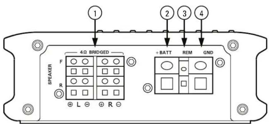
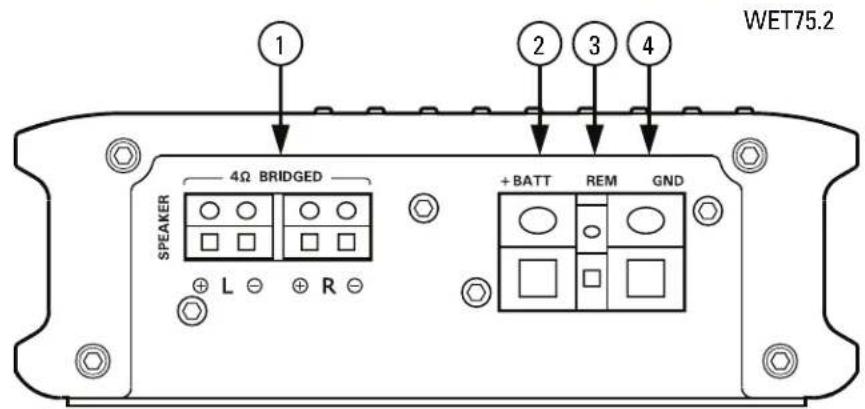
- Speakers - Connect speakers/subwoofoers to these terminals. Be sure to check wire for proper polarity. Never connect the speaker cables to the chassis ground.
- +BATT (+12 Volt Power) - Connect this terminal through a FUSE or CIRCUIT BREAKER to the positive terminal of the vehicle battery or the positive terminal of an isolated audio system battery. WARNING: Always protect this power cable by installing a fuse or circuit breaker of the appropriate gauge within 18 inches (45cm) of the battery terminal connection.
- Remote Turn On - This terminal turns on the amplifier when (+) 12 volt is applied to it. Connect it to the remote turn on lead of the head unit or signal source.
- GND - Run an equal gauge wire from the Ground (GND) terminal on the MTX amplifier to the negative terminal on the battery. Use the shortest distance possible. It is always a good idea to replace the factory ground at this time with a cable equal or larger than the new amplifier power cable. CAUTION: Do not connect this terminal directly to the vehicle battery ground terminal or any other factory ground points.
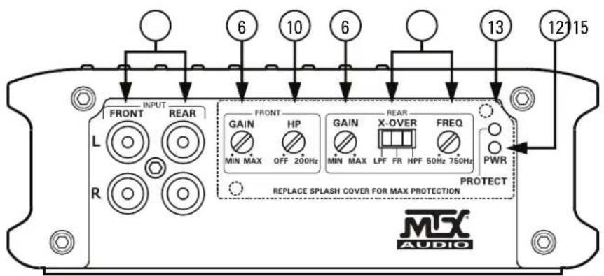
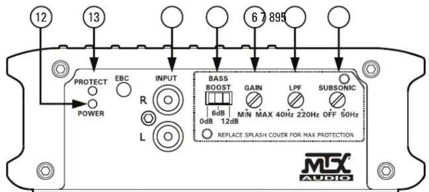
- RCA Input Jacks - These RCA input jacks are for use with source units that have RCA outputs. A source unit with a minimum level of 200mV is required for proper operation. The use of high quality twisted pair cables is recommended to decrease the possibility of radiated noise entering the system.
-
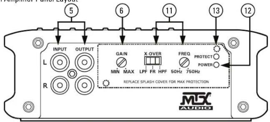
Gain Control - The Gain control will match the amplifier's sensitivity to the source units signal voltage. The operating range is 5V to 200mV. NOTE: This is NOT a volume control.
-
Low Pass Filter Control (Mono Block) - This control is used to select the desired low pass x -over frequency. The frequency can be adjusted from 40Hz to 220Hz for all bass mono models.
-
Subsonic Filter Control (Mono Block) - This control can filter out unwanted low frequency from 20Hz (OFF) to 50Hz. This function should only be used with vented enclosures.
-
Bass Boost Level Switch (Mono Block) - This switch can boost bass level by 0dB, 6dB, or 12dB. The boost frequency is centered at 50Hz.
-
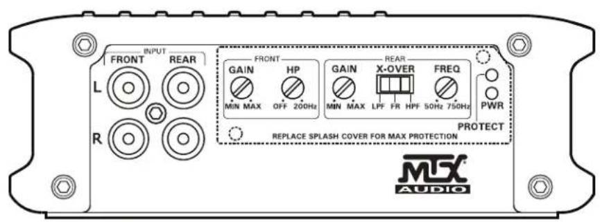
High Pass Filter (Full Range) - This controls the frequencies played for the front channels. Low frequencies can be cut off from OFF to 200Hz. At OFF position, no low frequencies cut off, meaning full range.
-
X-Over Mode and Frequency Control (Full Range) - These controls allow control over the frequencies played for the rear channels. There is an option for Low Pass, Full Range, or High Pass. In LP or HP mode, the crossover frequency can be tuned from 50Hz to 750Hz.
-
Power Indicator - This LED will light up when the amplifier is working properly.
-
Protection Indicator - The Red LED will light up and flash if there is a fault presented to the amplifier. Please disconnect the amplifier and resolve the fault before reconnecting the amplifier.
PANEL LAYOUT
4-Channel Amplifier Panel Layout
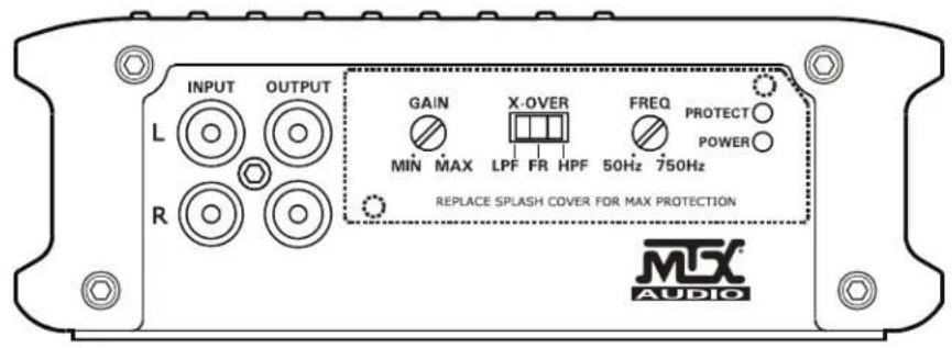
PANEL LAYOUT
2 Channel Amplifier Panel Layout
WET75.2
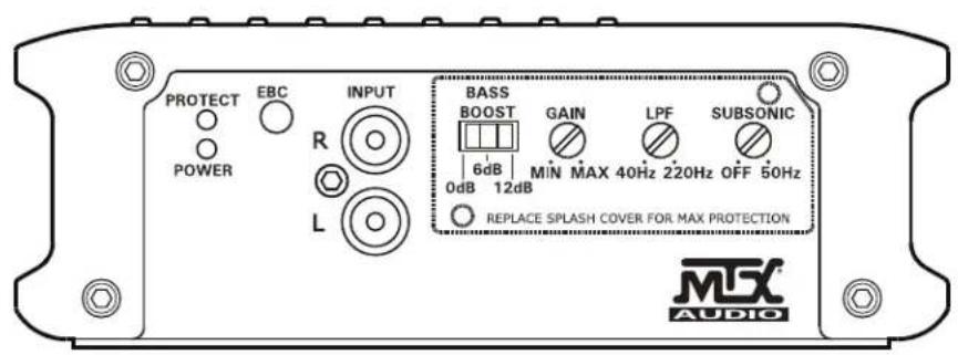
PANEL LAYOUT
Mono Block Amplifier Panel Layout
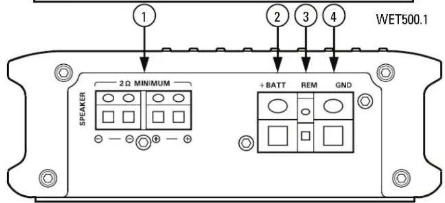
WET500.1
WIRING DIAGRAM
See page 26 for amplifier wiring diagrams.
INSTALLATION AND MOUNTING
MTX recommends your new Thunder Marine WET Series amplifier be installed by a 12 volt installation specialist. Any deviation from specified installation instructions can cause serious damage to the amplifier, speakers and/or vehicle's electrical system. Damage caused from improper installation is NOT covered under warranty. Please verify all connections prior to system turn on.
- Disconnect the vehicle's negative battery cable.
- Determine the mounting place for your MTX amplifier. Keep in mind there should be sufficient air flow for proper cooling. Mark the mounting holes from the amplifier to be drilled. Before drilling make sure all vehicle wires, gas lines, and gas tank are clear and will not interfere with installation. Drill the desired holes and mount the MTX amplifier.
- Install a positive (+) power cable from the vehicle's battery. Run the cable through the vehicle and connect it to the amplifier's (+BATT) terminal. Do not connect to the battery at this time. NOTE: Use only proper gauge wire for both positive and negative connections.
- Install a circuit breaker or fuse within 18 inches of the battery. This effectively lowers the risk of severe damage to you or your vehicle in case of a short circuit or accident. Make sure the circuit breaker is switched Off or the fuse is taken out of the fuse holder until all connections are made. Now connect your positive power cable to the positive battery terminal of the battery.
- Grounding - Run an equal gauge wire from the Ground (GND) terminal on the MTX amplifier to the battery compartment. Once installation is complete you will attach this cable to the negative battery terminal on the battery in step 9.
- Connect a Remote Turn-On wire from the source unit to the MTX amplifier's (REM) terminal. If the source unit does not have a dedicated Remote Turn-On lead, you may connect to the source unit's Power Antenna lead.
- Supply the signal to your MTX amplifier by connecting the signal cables using high quality RCA to the corresponding outputs at the source unit and inputs of the amplifier.
- Connect your speakers to your MTX amplifier's speaker terminals using the correct gauge speaker wire. Your MTX Thunder Marine amp can drive a 2 minimum load for optimum power.
- Double check all previous installation steps, in particular, wiring and component connections. Once verified, reconnect the vehicle's negative battery cable, turn the circuit breaker On or place the fuse in the fuse holder.
NOTE: Gain Levels on the amplifier should be turned all the way down (counter clockwise) before proceeding with adjustments.
INSTALLATION
For proper performance and safety, MTX recommends installing an inline fuse per the owner's manual instructions according to the following.
| WET500.1 60A Fuse | |
| WET75.2 30A Fuse | |
| WET75.4 60A Fuse |
TROUBLESHOOTING
| Problem Cause Solution | ||
| No LED Indication | No +12V at Remote Connection Supply | +12V to Terminal |
| No +12V at Power Connection Supply | +12V to Terminal | |
| Insufficient Ground Connection Verify | Ground Connection | |
| Blown Power Fuse Replace Fuse | ||
| Power LED On, No Output | Volume on Source Unit Off Increase Volume on Source Unit | |
| Speaker Connections Not Made Make | Speaker Connections | |
| Gain Control on Amplifier Off Turn Up Gain | ||
| Signal Processing Units Off Apply Power to Signal Processor | ||
| All Speakers Blown Replace Speakers | ||
| Output Distorted | Head Unit Volume Set Too High Lower Head Unit Volume | |
| Amplifier Gain Set Too High Lower Amplifier Gain | ||
| Balance Reversed | Speaker Wire L & R Reversed | Correct Speaker Wire Orientation |
| RCA Inputs Reversed Reverse RCA Inputs | ||
| Bass is Weak | Speakers Wired Out of Phase | Wire Speakers with Correct Phase |
| Not Using MTX Subwoofer | Buy MTX Subwoofer | |
| Blowing Fuses | Excessive Output Levels | Lower the Volume |
| Amplifier Defective | Return for Service | |
SPECIFICATIONS
| Model WET500.1 WET75.2 WET75.4 | |||
| Description 500 W RMS Mono 2x | 75 W RMS 4 x 75 W RMS | ||
| RMS Power at 14.4V | |||
| 1Ω Load NA NA NA | |||
| 2Ω Load 500 W RMS 2x 100W RMS | S 4 x 100 W RMS | ||
| 4Ω Load 300 W RMS 2 x 75 W RMS | S 4 x 75 W RMS | ||
| Features | |||
| Input Level 0.2 - 5V 0.2 - 5V 0.2 - 5V | |||
| Frequency Response 20Hz - 220Hz | 15Hz - 25kHz | 15Hz - 25kHz | |
| Low Pass Filter (LPF) | 40Hz - 220Hz | 50Hz - 750Hz (Rear) | 50Hz - 750Hz (Rear) |
| High Pass Filter (HPF) | NA | 50Hz - 750Hz (Rear) | 10Hz - 200Hz (Front) 50Hz - 750Hz (Rear) |
| Subsonic Filter | 20Hz - 50Hz | NA NA | |
| THD at 4Ω, 1W | <0.3% | <0.05% | <0.05% |
| Signal-to-Noise Ratio | >75dB | >78dB | >78dB |
| Bass Boost | 0 - 6dB - 12dB Switchable | NA NA | |
| Best Efficiency at 4Ω | >80% | >60% | >60% |
| Minimum Load | 2Ω | 2Ω | 2Ω |
| External Bass Control (EBC) Optional Remote | Yes NA | NA | |
| Low Voltage Protection | Yes, Protect <8V | Yes, Protect <8V | Yes, Protect <8V |
| Short Circuit Test @ Max Power | Pass | Pass | Pass |
| Overheat Protect Temperature | Protect at 80°C / 176°F | Protect at 80°C / 176°F | Protect at 80°C / 176°F |
| Components & PCB | SMD Parts / Double Sided FR-4 PCB | SMD Parts / Double Sided FR-4 PCB | SMD Parts / Double Sided FR-4 PCB |
| Dimensions | |||
| Height | 2.25" (56.5mm) | 2.25" (56.5mm) | 2.25" (56.5mm) |
| Width | 6.31" (160mm) | 6.31" (160mm) | 6.31" (160mm) |
| Length | 9.02" (229mm) | 9.45" (240mm) | 12.21" (310mm) |
INFORMACION DEL PRODUCTO
Número de modelo
Numero de série
THUNDER1000.1 - Fusivel 100A WET500.1 - Fusivel 60A WET75.4 - Fusivel 60A
SOLUTION DE PROBLEMAS
INFORMATIONS SUR LE PRODUIT
Modèle
NOTE: Equivalent parallel woofer load cannot be less than the minimum load rating. The two negative terminals are paralleled inside the amplifiers, as are the two positive terminals. These are monoblock amplifiers, not multi-channel amplifiers. The minimum load for the WET500.1 amplifier is 2Ω.
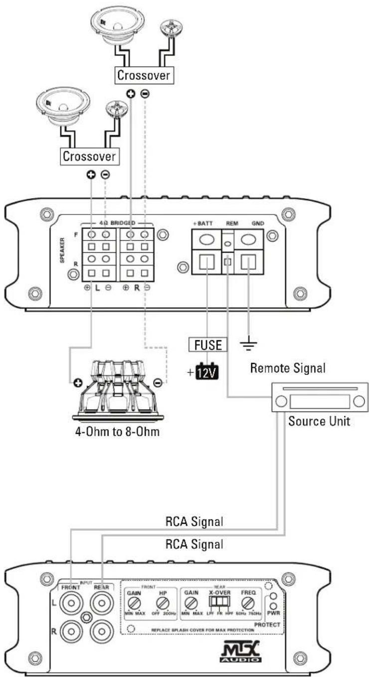
WET75.4 Amplifier Wiring (4-Channel Mode)
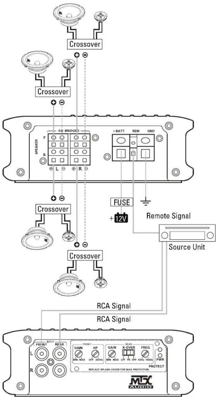
WIRING DIAGRAM
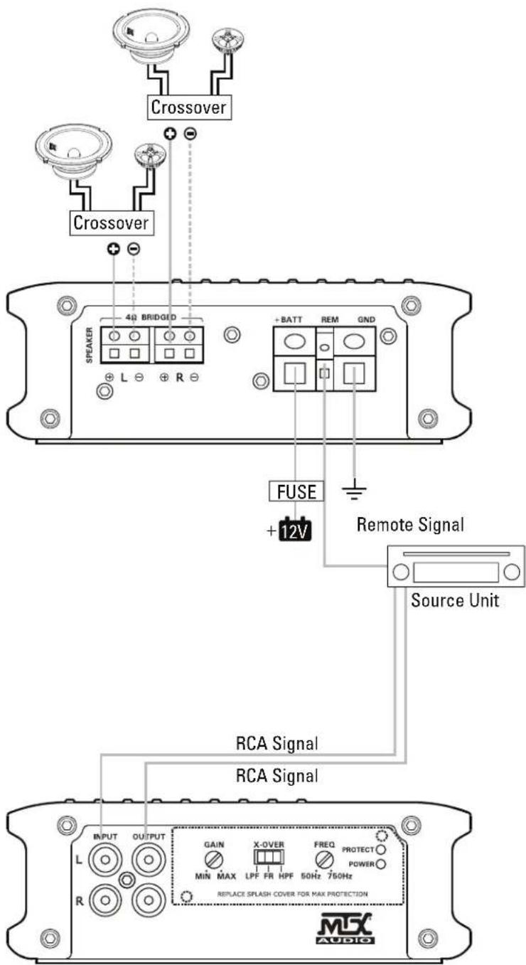
WET75.4 Amplifier Wiring (3-Channel Mode)
WIRING DIAGRAM
WET75.2 Amplifier Wiring (2-Channel Mode)
NOTES:
CN535
©2014 Mitek Corporation. All rights reserved. MTX is a trademark of Mitek Corporation. Designed and Engineered in the U.S.A.
Due to continual product development, all specifications are subject to change without notice.
MTX Audio, 4545 East Baseline Rd. Phoenix, AZ 85042 U.S.A.
MTX004714 RevB 4/14 21A10167-AW0014695