
X470 Gaming Plus - Motherboard MSI - Free user manual and instructions
Find the device manual for free X470 Gaming Plus MSI in PDF.

| Product Type | ATX Motherboard |
| Brand | MSI |
| Model | X470 Gaming Plus |
| Form Factor | ATX (30.5 cm x 24.4 cm) |
| Chipset | AMD X470 |
| CPU Socket | AM4 (supports Ryzen, A-series, Athlon) |
| RAM Memory | 4 x DDR4, up to 64 GB, dual channel, up to 3466 MHz OC |
| Expansion Slots | 2 x PCIe 3.0 x16, 1 x PCIe 2.0 x16 (x4), 3 x PCIe 2.0 x1 |
| Storage | 6 x SATA 6 Gb/s, 2 x M.2 (PCIe 3.0 x4 / SATA) |
| USB Ports | 2 x USB 3.1 Gen2 (Type-A), 4 x USB 3.1 Gen1 (back panel), 4 x USB 3.1 Gen1 (internal), 6 x USB 2.0 |
| Video Outputs | 1 x DVI-D, 1 x HDMI 1.4 |
| Audio | Realtek ALC892, 7.1 channels, optical S/PDIF |
| Network | Realtek 8111H Gigabit LAN |
| Power Requirement | ATX 24-pin + 12V 8-pin + 4-pin |
| Special Features | Mystic Light RGB, Game Boost, Audio Boost, Nahimic 2.5, PCIe Steel Armor, DDR4 Boost, X-Boost |
| Fan Connectors | 1 x CPU (4-pin), 1 x pump (4-pin), 4 x system (4-pin) |
| BIOS | UEFI AMI, 128 Mb flash, Click BIOS 5 |
| Security | ESD protection, chassis intrusion detection, Clear CMOS jumper/button |
| Maintenance and Cleaning | Dust with dry cloth, avoid moisture, handle with antistatic wrist strap |
| Spare Parts and Repairability | CR2032 CMOS battery, SATA cables included, manual available online |
| Included Software | Command Center, Live Update 6, Mystic Light, Gaming App, RAMDisk, Norton Internet Security |
Frequently Asked Questions - X470 Gaming Plus MSI
User questions about X470 Gaming Plus MSI
0 question about this device. Answer the ones you know or ask your own.
Ask a new question about this device
Download the instructions for your Motherboard in PDF format for free! Find your manual X470 Gaming Plus - MSI and take your electronic device back in hand. On this page are published all the documents necessary for the use of your device. X470 Gaming Plus by MSI.
USER MANUAL X470 Gaming Plus MSI
Thank you for purchasing the MSI® X470 GAMING PLUS motherboard. This Quick Start section provides demonstration diagrams about how to install your computer. Some of the installations also provide video demonstrations. Please link to the URL to watch it with the web browser on your phone or tablet. You may have even link to the URL by scanning the QR code.
Kurzanleitung
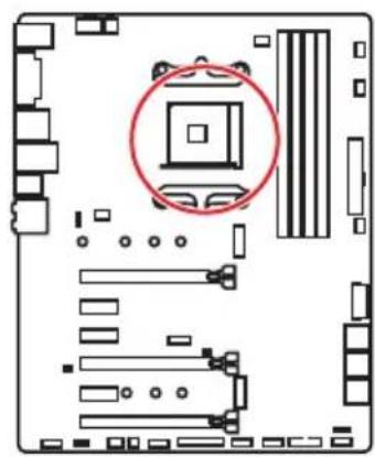
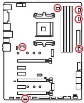
If you are installing the screw-type CPU heatsink, please follow the figure below to remove the retention module first and then install the heatsink.
Safety Information 2
Specifications 3
Rear I/O Panel 8
LAN Port LED Status Table. 8
Audio Ports Configuration 8
Realtek HD Audio Manager 9
Overview of Components 11
CPU Socket 12
DIMM Slots. 13
PCI_E1~6:PCIe Expansion Slots 14
M2_1~2: M.2 Slots (Key M) 16
SATA1~6: SATA 6Gb/s Connectors 17
JLPT1: Parallel Port Connector 17
CPU_PWR1, CPU_PWR2, ATX_PWR1: Power Connectors 18
JUSB1~2: USB 2.0 Connectors 19
JUSB3-4: USB 3.1 Gen1 Connectors 19
CPU_FAN1, PUMP_FAN1, SYS_FAN1~4: Fan Connectors. 20
JAUD1: Front Audio Connector 21
JCI1: Chassis Intrusion Connector 21
JFP1, JFP2: Front Panel Connectors 22
JTPM1: TPM Module Connector 22
JCOM1: Serial Port Connector 23
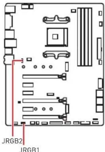
JRGB1, JRGB2: RGB LED Connectors 23
JBAT1: Clear CMOS [Reset BIOS] Jumper 24
CLR_CMOS1: Clear CMOS Button 24
BIOS Setup 25
EnteringBIOS Setup 25
ResettingBIOS 26
UpdatingBIOS 26
EZ Mode 27
Advanced Mode 29
OC Menu 30
Software Description 35
Installing Windows 10 35
35
35
Safety Information
-
The components included in this package are prone to damage from electrostatic discharge (ESD). Please adhere to the following instructions to ensure successful computer assembly.
-
Ensure that all components are securely connected. Loose connections may cause the computer to not recognize a component or fail to start.
-
Hold the motherboard by the edges to avoid touching sensitive components.
-
It is recommended to wear an electrostatic discharge (ESD) wrist strap when handling the motherboard to prevent electrostatic damage. If an ESD wrist strap is not available, discharge yourself of static electricity by touching another metal object before handling the motherboard.
-
Store the motherboard in an electrostatic shielding container or on an anti-static pad whenever the motherboard is not installed.
-
Before turning on the computer, ensure that there are no loose screws or metal components on the motherboard or anywhere within the computer case.
-
Do not boot the computer before installation is completed. This could cause permanent damage to the components as well as injury to the user.
-
If you need help during any installation step, please consult a certified computer technician.
-
Always turn off the power supply and unplug the power cord from the power outlet before installing or removing any computer component.
-
Keep this user guide for future reference.
-
Keep this motherboard away from humidity.
-
Make sure that your electrical outlet provides the same voltage as is indicated on the PSU, before connecting the PSU to the electrical outlet.
-
Place the power cord such a way that people can not step on it. Do not place anything over the power cord.
-
All cautions and warnings on the motherboard should be noted.
-
If any of the following situations arises, get the motherboard checked by service personnel:
Liquid has penetrated into the computer.
The motherboard has been exposed to moisture.
- The motherboard does not work well or you can not get it work according to user guide.
The motherboard has been dropped and damaged.
The motherboard has obvious sign of breakage.
- Do not leave this motherboard in an environment above 60^ [140^] , it may damage the motherboard.
Specifications
Continued on next page
| CPU | Supports AMD® Ryzen™ Desktop Processors and AMD® A-Series/Athlon™ Processors for Socket AM4 |
| Chipset AMD | ® X470 Chipset |
| Memory | · 4x DDR4 memory slots, support up to 64GB · Supports DDR4 1866/ 2133/ 2400/ 2667 Mhz by JEDEC and 2667/ 2800/ 2933/ 3000/ 3066/ 3200/ 3466 Mhz by A-XMP OC MODE* · Dual channel memory architecture · Supports non-ECC UDIMM memory · Supports ECC UDIMM memory * A-series/ Athlon™ processors support up to 2400 MHz. And the supporting frequency of memory varies with installed processor. Please refer www.msi.com for more information on compatible memory. |
| Expansion Slots | · 2x PCIe 3.0 x16 slots (PCIE_1, PCIE_4) · Ryzen™ Desktop Processors support x16/x0, x8/x8 mode · Ryzen™ Desktop Processors with Radeon Vega Graphics and A-Series/Athlon™ Processors support x8/x0 mode · 1x PCIe 2.0 x16 slot (PCIE_6, supports x4 mode)* · 3x PCIe 2.0 x1 slots * PCI_E6 slot will be unavailable when installing M.2 PCIe SSD in M2_2 slot. |
| Onboard Graphics | · 1x DVI-D port, supports a maximum resolution of 1920x1200@60Hz* · 1x HDMI™ port 1.4, supports a maximum resolution of 4096x2160@30Hz* * Only support when using Ryzen™ Desktop Processors with Radeon Vega Graphics and A-Series/Athlon™ Processors * Maximum shared memory of 2048 MB |
| Multi-GPU | · Ryzen™ Desktop Processors · Supports 3-Way AMDrossFire™ Technology · Ryzen™ Desktop Processors with Radeon Vega Graphics and A-Series/Athlon™ Processors · Supports 2-Way AMDrossFire™ Technology |
| LAN 1x Realtek | ® 8111H Gigabit LAN controller |
Continued from previous page
| Storage | • 6x SATA 6Gb/s ports (from AMD70 Chipset) • 2x M.2 ports (Key M)* • M2_1 slot (from AMDprocessor) supports PCIe 3.0 x4 (Ryzen™ Desktop Processors) or PCIe 3.0 x2 (A-series/Athlon™ Processors) 2242/ 2260 /2280/ 22110 storage devices • M2_2 slot (from AMD470 Chipset) supports PCIe 2.0 x4 and SATA 6Gb/s 2242/ 2260 /2280 storage devices * SATA1 port will be unavailable when installing SATA M.2 SSD in M2_2 slot. * PCI_E6 slot will be unavailable when installing PCIe M.2 SSD in M2_2 slot. |
| RAID | AMD® X470 Chipset • Supports RAID 0, RAID 1 and RAID 10 for SATA storage devices |
| USB | • ASMedASM1143 Chipset • 2x USB 3.1 Gen2 (SuperSpeed USB 10Gbps) Type-A ports on the back panel • AMD470 Chipset • 4x USB 3.1 Gen1 (SuperSpeed USB) ports through the internal USB connectors • 6x USB 2.0 (High-speed USB) ports (2 Type-A ports on the back panel, 4 ports available through the internal USB connectors) • AMCPU • 4x USB 3.1 Gen1 (SuperSpeed USB) Type-A ports on the back panel |
| Audio | • Realtek C892 Codec • 7.1-Channel High Definition Audio • Supports S/PDIF output |
Continued on next page
Continued from previous page
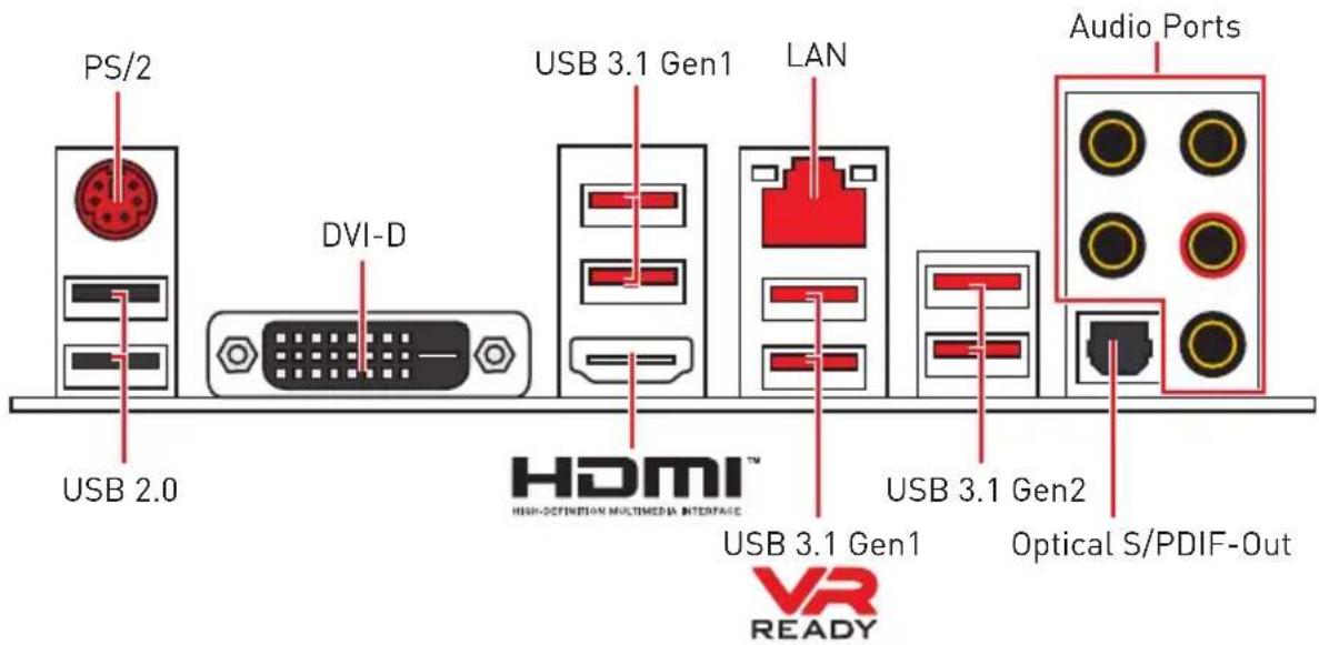
| Back Panel Connectors | · 1x PS/2 keyboard/ mouse combo port · 2x USB 2.0 Type-A ports · 1x DVI-D port · 1x HDMI™ 1.4 port · 4x USB 3.1 Gen1 Type-A ports · 1x LAN (RJ45) port · 2x USB 3.1 Gen2 Type-A ports · 5x OFC audio jacks · 1x Optical S/PDIF OUT connector |
| Internal Connectors | · 1x 24-pin ATX main power connector · 1x 8-pin ATX 12V power connector · 1x 4-pin ATX 12V power connector · 6x SATA 6Gb/s connectors · 2x USB 2.0 connectors (support additional 4 USB 2.0 port) · 2x USB 3.1 Gen1 connectors (support additional 4 USB 3.1 Gen1 ports) · 1x 4-pin CPU fan connector · 1x 4-pin PUMP fan connector (supports up to 2A) · 4x 4-pin system fan connectors · 1x Serial port connector · 1x Parallel port connector · 2x 5050 RGB LED strip 12V connectors · 1x TPM module connector · 1x Front panel audio connector · 2x System panel connectors · 1x Chassis Intrusion connector · 1x Clear CMOS jumper · 1x Clear CMOS button |
| I/O Controller NUVOTON NCT6795D Controller Chip | |
Continued on next page
Continued from previous page
| Hardware Monitor | • CPU/System temperature detection • CPU/System fan speed detection • CPU/System fan speed control |
| Form Factor | • ATX Form Factor • 12 in. x 9.6 in. (30.5 cm x 24.4 cm) |
| BIOS Features | • 1x 128 Mb flash • UEFI AMI BIOS • ACPI 6.1, SM BIOS 2.8 • Multi-language |
| Software | • Drivers • APP MANAGER • COMMAND CENTER • LIVE UPDATE 6 • MYSTIC LIGHT • SUPER CHARGER • GAMING APP • RAMDISK • X-BOOST • SMART TOOL • Nahimic Audio • Open Broadcaster Software (OBS) • Norton™ Internet Security Solution • Google Chrome™, Google Toolbar, Google Drive • CPU-Z MSI GAMING |
Continued on next page
Continued from previous page
| Special Features | · Audio · Audio Boost · Voice Boost · Nahimic 2.5 · Storage · Turbo M.2 · Fan · Pump Fan · Smart Fan Control · LED · Mystic Light · Mystic Light Extension · Mystic light SYNC · EZ DEBUG LED · Protection · PCI-E Steel Armor · Performance · Multi GPU-CrossFire Technology · DDR4 Boost · GAME Boost · X-Boost · A-XMP · Stability · 7000+ Quality Test · VR · VR Ready · Gamer Experience · RAMDisk · BIOS · Click BIOS 5 · Certification · GAMING Certified |
Rear I/O Panel
LAN Port LED Status Table
| Link/ Activity LED | Speed LED | ||
| Status Description | Status Description | ||
| Off No link | Off 10 Mbps connection | ||
| Yellow Linked | Green 100 Mbps connection | ||
| Blinking Data activity | Orange 1 Gbps connection | ||
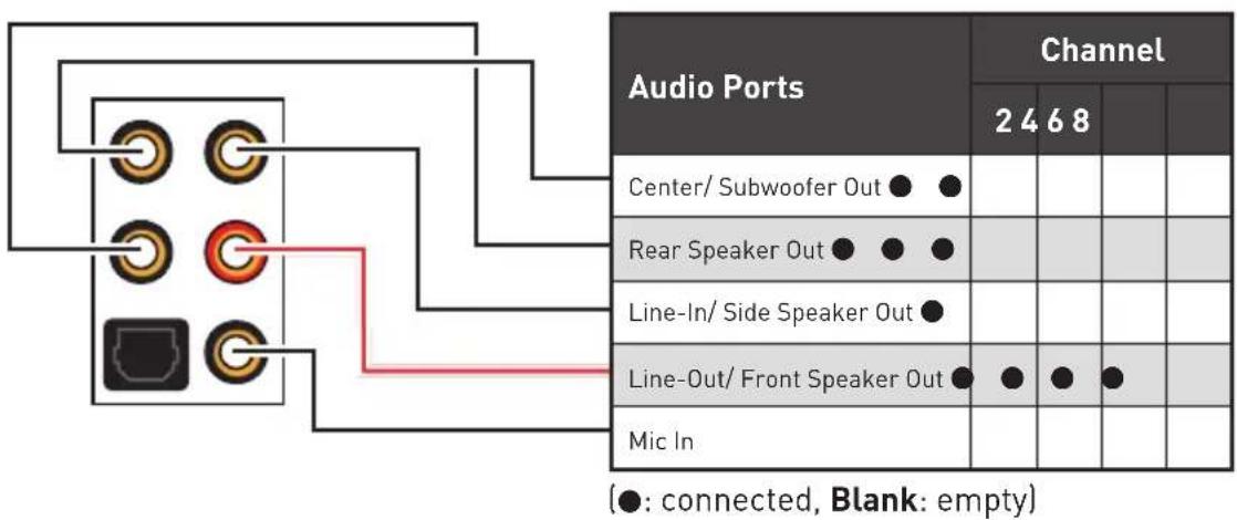
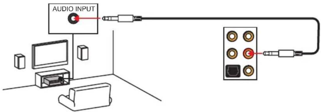
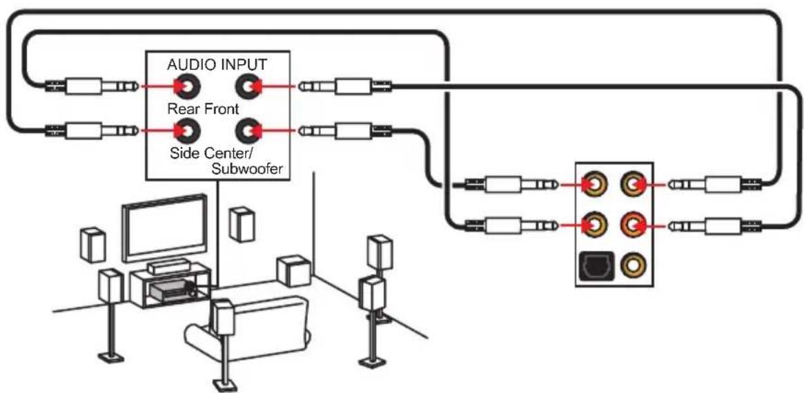
Audio Ports Configuration
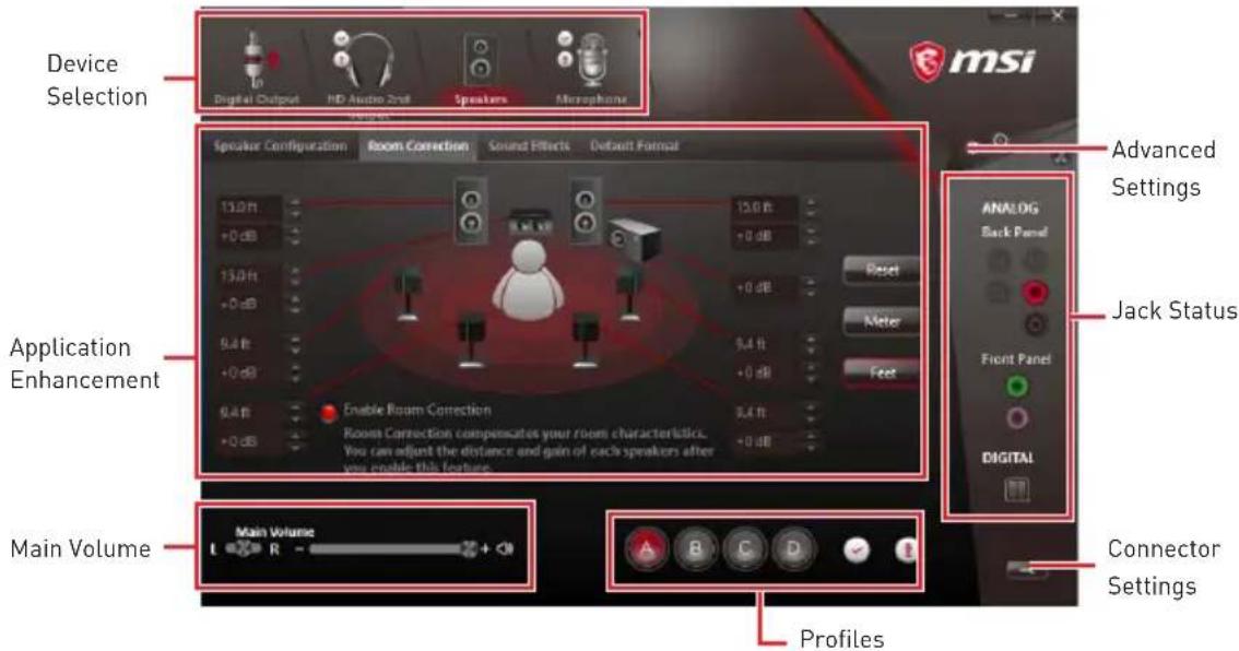
Realtek HD Audio Manager
After installing the Realtek HD Audio driver, the Realtek HD Audio Manager icon will appear in the system tray. Double click on the icon to launch.
-
Device Selection - allows you to select a audio output source to change the related options. The check sign indicates the devices as default.
-
Application Enhancement - the array of options will provide you a complete guidance of anticipated sound effect for both output and input device.
-
Main Volume - controls the volume or balance the right/left side of the speakers that you plugged in front or rear panel by adjust the bar.
-
Profiles - toggles between profiles.
-
Advanced Settings - provides the mechanism to deal with 2 independent audio streams.
-
Jack Status - depicts all render and capture devices currently connected with your computer.
-
Connector Settings - configures the connection settings.
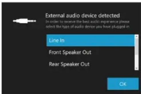
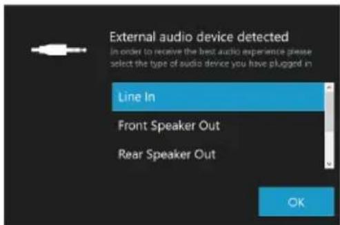
Auto popup dialog
When you plug into a device at an audio jack, a dialogue window will pop up asking you which device is current connected.
Each jack corresponds to its default setting as shown on the next page.
Audio jacks to headphone and microphone diagram

Audio jacks to stereo speakers diagram
Audio jacks to 7.1-channel speakers diagram
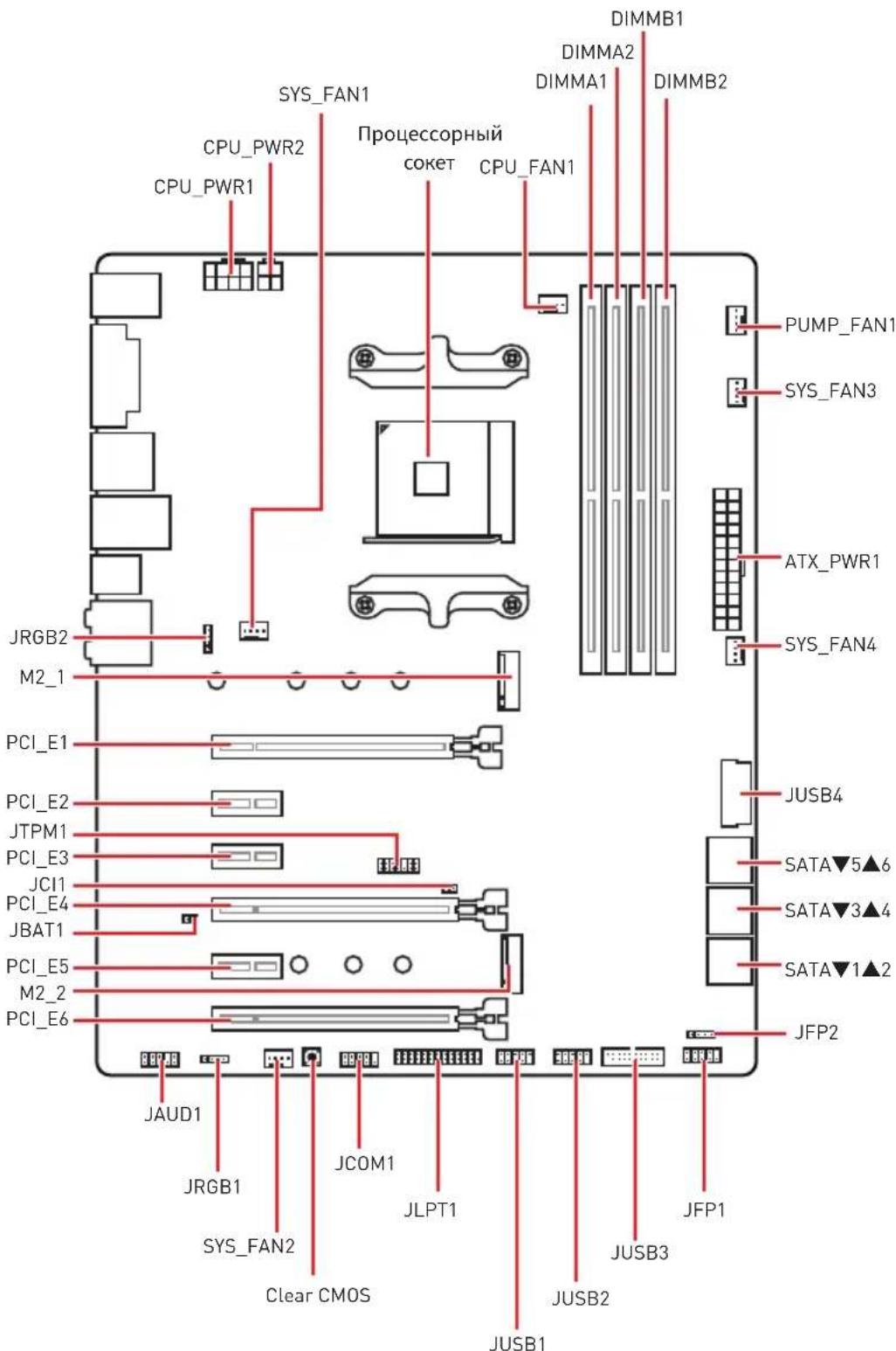
Overview of Components

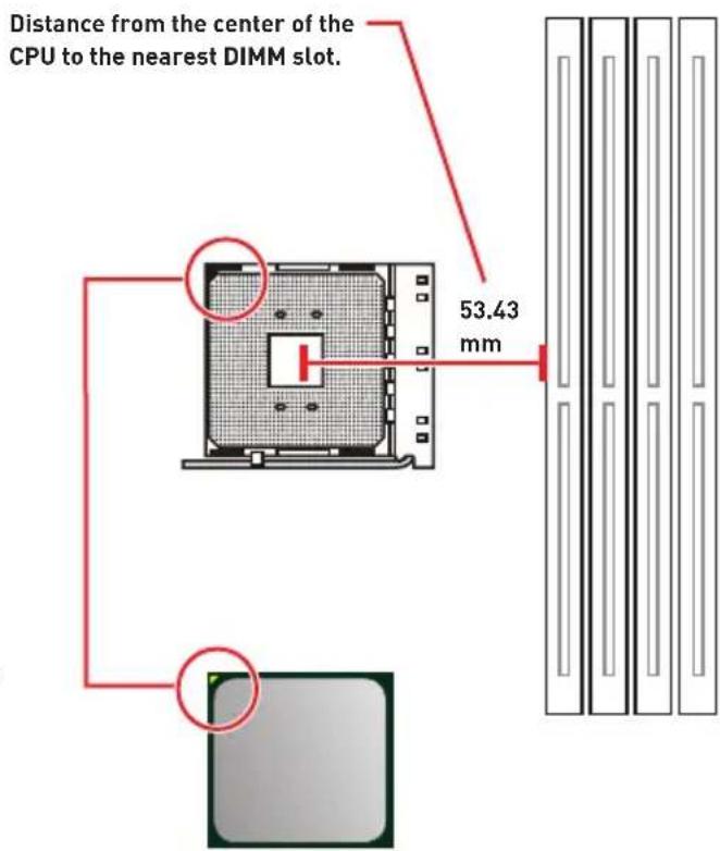
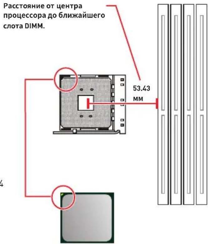
CPU Socket

Introduction to the AM4 CPU
The surface of the AM4 CPU has a yellow triangle to assist in correctly lining up the CPU for motherboard placement. The yellow triangle is the Pin 1 indicator.
Important
When changing the processor, the system configuration could be cleared and reset BIOS to default values, due to the AM4 processor's architecture.
Always unplug the power cord from the power outlet before installing or removing the CPU.
When installing a CPU, always remember to install a CPU heatsink. A CPU heatsink is necessary to prevent overheating and maintain system stability.
Confirm that the CPU heatsink has formed a tight seal with the CPU before booting your system.
Overheating can seriously damage the CPU and motherboard. Always make sure the cooling fans work properly to protect the CPU from overheating. Be sure to apply an even layer of thermal paste (or thermal tape) between the CPU and the heatsink to enhance heat dissipation.
If you purchased a separate CPU and heatsink/ cooler, Please refer to the documentation in the heatsink/ cooler package for more details about installation.
This motherboard is designed to support overclocking. Before attempting to overclock, please make sure that all other system components can tolerate overclocking. Any attempt to operate beyond product specifications is not recommended. MSI® does not guarantee the damages or risks caused by inadequate operation beyond product specifications.
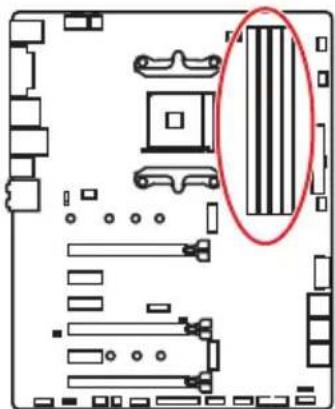
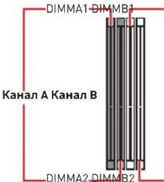
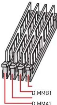
DIMM Slots

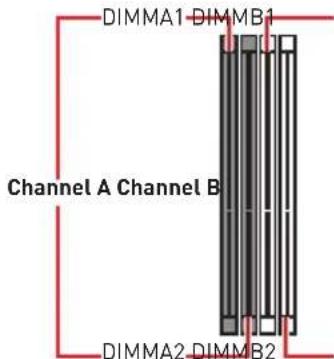

Memory module installation recommendation
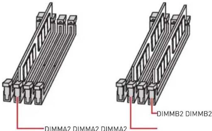
Important
Always insert memory modules in the DIMMA2 slot first.
Due to chipset resource usage, the available capacity of memory will be a little less than the amount of installed.
Based on the processor specification, the Memory DIMM voltage below 1.35V is suggested to protect the processor.
Some memory modules may operate at a lower frequency than the marked value when overclocking due to the memory frequency operates dependent on its Serial Presence Detect (SPD). Go to BIOS and find the DRAM Frequency to set the memory frequency if you want to operate the memory at the marked or at a higher frequency.
It is recommended to use a more efficient memory cooling system for full DIMMs installation or overclocking.
The stability and compatibility of installed memory module depend on installed CPU and devices when overclocking.
Due to AM4 CPU/memory controller official specification limitation, the frequency of memory modules may operate lower than the marked value under the default state. Please refer www.msi.com for more information on compatible memory.
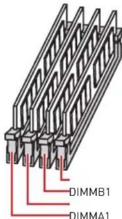
PCI_E1~6: PCIe Expansion Slots
For Ryzen™ Desktop processors
* For Ryzen™ Desktop Processors with Radeon Vega Graphics & A-Series/Athlon™ Processors
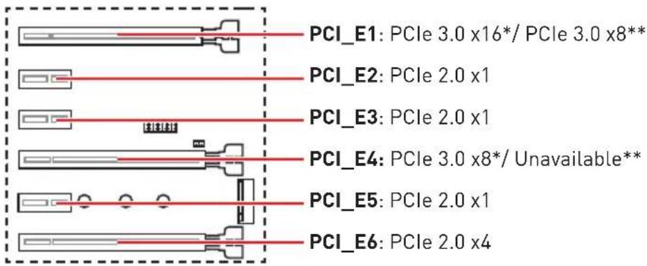
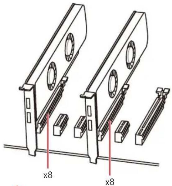
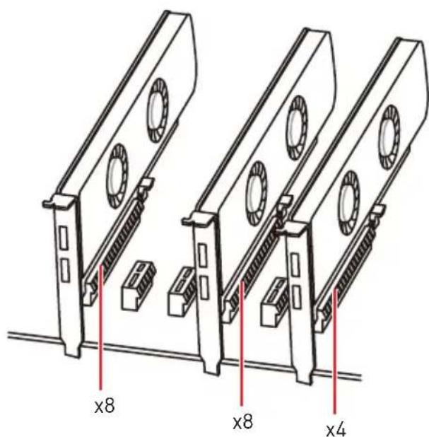
Multiple graphics cards installation recommendation (Ryzen™ series processors)
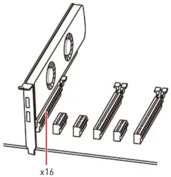
! Important
If you install a large and heavy graphics card, you need to use a tool such as MSI Gaming Series Graphics Card Bolster to support its weight to prevent deformation of the slot.
For a single PCIe x16 expansion card installation with optimum performance, using the PCI_E1 slot is recommended.
When adding or removing expansion cards, always turn off the power supply and unplug the power supply power cable from the power outlet. Read the expansion card's documentation to check for any necessary additional hardware or software changes.
PCIe bandwidth table
For Ryzen™ Desktop processors
| Slot Single 2-Way | ||||
| PCI_E1 (CPU) Gen 3.0 | x 16* Gen 3.0 x 8* | |||
| PCI_E2 (PCH) Gen 2.0 | x 1 Gen 2.0 x 1 | |||
| PCI_E3 (PCH) Gen 2.0 | x 1 Gen 2.0 x 1 | |||
| PCI_E4 (CPU) — Gen 3.0 x 8* | ||||
| PCI_E5 (PCH) Gen 2.0 | x 1 Gen 2.0 x 1 | |||
| PCI_E6 (PCH) Gen 2.0 | x 4 — Gen 2.0 x 4 — | |||
| M2_1 (CPU) Gen 3.0 x | 4 Gen 3.0 x 4 | |||
| M2_2 (PCH) — Gen | 2.0 x 4 — Gen 2.0 x 4 | |||
: unavailable, *: graphics card]
For Ryzen™ Desktop Processors with Radeon Vega Graphics & A-Series/Athlon™ Processors
| Slot Single | ||
| PCI_E1 (CPU) Gen 3.0 x 8* | ||
| PCI_E2 (PCH) | Gen 2.0 x 1 | |
| PCI_E3 (PCH) | Gen 2.0 x 1 | |
| PCI_E4 (CPU) | — | |
| PCI_E5 (PCH) | Gen 2.0 x 1 | |
| PCI_E6 (PCH) | Gen 2.0 x 4 — | |
| M2_1 (CPU) | Gen 3.0 x 2**/ Gen 3.0 x 4*** | |
| M2_2 (PCH) | — Gen 2.0 x 4 | |
(—: unavailable, : graphics card, : for A-Series/Athlon™ Processors, **: for Ryzen™ Desktop Processors with Radeon Vega Graphics)
Important
PCI_E6 slot will be unavailable when installing PCIe M.2 SSD in M2_2 slot.
M2_1~2: M.2 Slots (Key M)
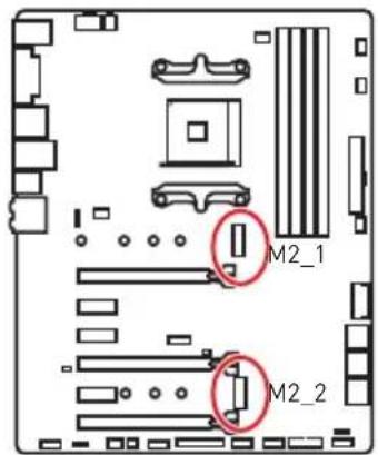

SATA1 port will be unavailable when installing SATA M.2 SSD in M2_2 slot.
PCI_E6 slot will be unavailable when installing PCIe M.2 SSD in M2_2 slot.
M2_1 slot only supports PCIe mode.


Watch the video to learn how to Install M.2 SSD.
http://youtu.be/JCTFABytrYA
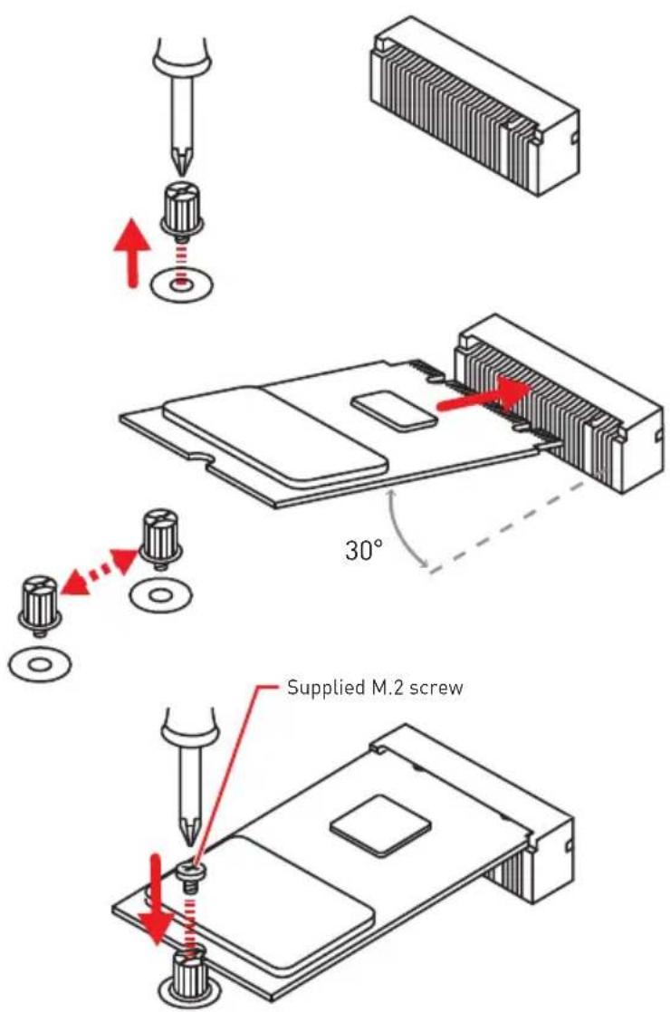
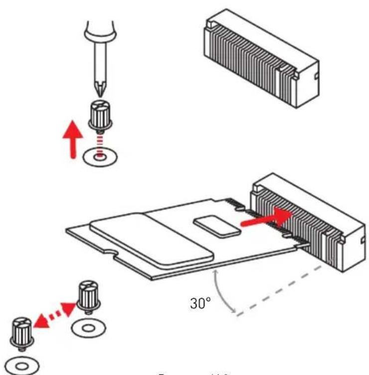
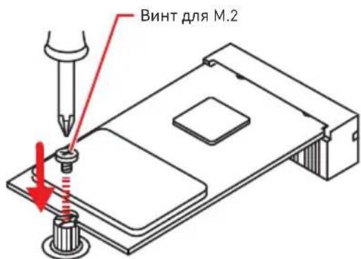
Installing M.2 SSD
- Loosen the M.2 riser screw from the motherboard.
- Move and fasten the M.2 riser screw to the appropriate location according your M.2 SSD size.
- Insert your M.2 SSD into the M.2 slot at a 30-degree angle.
- Secure the M.2 SSD in place with the supplied M.2 screw.
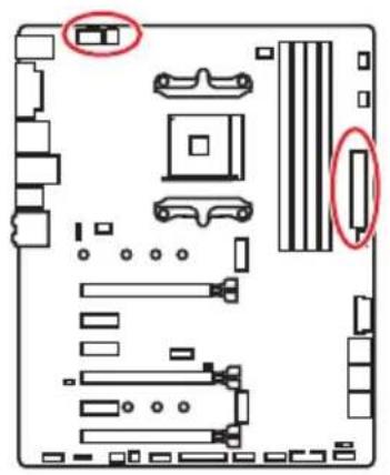
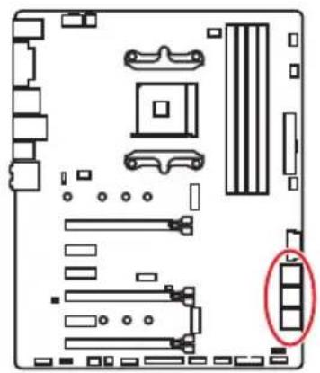
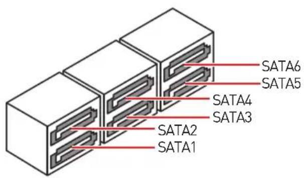
SATA1~6: SATA 6Gb/s Connectors
These connectors are SATA 6Gb/s interface ports. Each connector can connect to one SATA device.

Important
SATA1 port will be unavailable when installing SATA M.2 SSD in M2_2 slot.
Please do not fold the SATA cable at a 90-degree angle. Data loss may result during transmission otherwise.
SATA cables have identical plugs on either sides of the cable. However, it is recommended that the flat connector be connected to the motherboard for space saving purposes.
JLPT1: Parallel Port Connector
This connector allows you to connect the optional parallel port with bracket.
| 2 1 26 25 | |||||
| 1 | RSTB# 2 AFD# 3 PRND0 | ||||
| 4 | ERR# 5 PRND1 6 | PINIT# | |||
| 7 | PRND2 8 | LPT_SLIN# 9 PRND3 | |||
| 10 | Ground | 11 | PRND4 | 12 | Ground |
| 13 | PRND5 | 14 | Ground | 15 | PRND6 |
| 16 | Ground | 17 | PRND7 | 18 | Ground |
| 19 | ACK# 20 Ground | 21 | BUSY | ||
| 22 | Ground | 23 | PE | 24 | Ground |
| 25 | SLCT | 26 | No Pin | ||
CPU_PWR1, CPU_PWR2, ATX_PWR1: Power Connectors
These connectors allow you to connect an ATX power supply.
| CPU_PWR1 | |||
| 1 Gound 5 | +12V | ||
| 2 Ground 6 | +12V | ||
| 3 Ground 7 | +12V | ||
| 4 Ground 8 | +12V | ||
| CPU_PWR2 | |||
| 1 Ground 3 | +12V | ||
| 2 Ground 4 | +12V | ||
| 12 24 ATX_PWR1 1 13 | 1 +3.3V 13 +3.3V | ||
| 2 +3.3V 14 -12V | |||
| 3 Ground 15 Ground | |||
| 4 +5V 16 PS-ON# | |||
| 5 Ground 17 Ground | |||
| 6 +5V 18 Ground | |||
| 7 Ground 19 Ground | |||
| 8 PWR OK 20 Res | |||
| 9 5V SB 21 +5V | |||
| 10 +12V 22 +5V | |||
| 11 +12V 23 +5V | |||
| 12 +3.3V 24 Ground |
! Important
Make sure that all the power cables are securely connected to a proper ATX power supply to ensure stable operation of the motherboard.
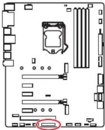
JUSB1~2: USB 2.0 Connectors
These connectors allow you to connect USB 2.0 ports on the front panel.
| 2 10 1 9 | |||
| 1 | VCC | 2 | VCC |
| 3 USB0-4 | USB1- | ||
| 5 USB0+6 | USB1+ | ||
| 7 Ground 8 | Ground | ||
| 9 No Pin | 10 | NC | |
Important
- Note that the VCC and Ground pins must be connected correctly to avoid possible damage.
- In order to recharge your iPad,iPhone and iPod through USB ports, please install MSI® SUPER CHARGER utility.
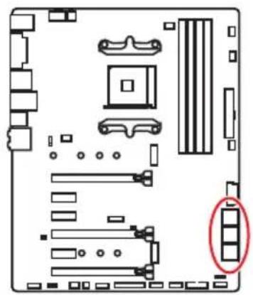
JUSB3~4: USB 3.1 Gen1 Connectors
These connectors allow you to connect USB 3.1 Gen1 ports on the front panel.
| JUSB3 | 10 JUSB4 | ||
| 1 Power 11 USB2.0+ | |||
| 2 USB3_RX_DN 12 USB2.0- | |||
| 3 USB3_RX_DP 13 Ground | |||
| 4 Ground 14 | USB3_TX_C_DP | ||
| 5 | USB3_TX_C_DN | 15 | USB3_TX_C_DN |
| 6 | USB3_TX_C_DP | 16 | Ground |
| 7 Ground 17 | USB3_RX_DP | ||
| 8 | USB2.0- | 18 | USB3_RX_DN |
| 9 | USB2.0+ | 19 | Power |
| 10 | NC | 20 | No Pin |
Important
Note that the Power and Ground pins must be connected correctly to avoid possible damage.
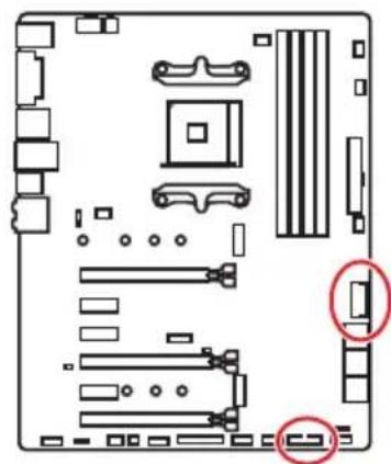
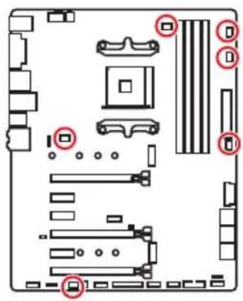
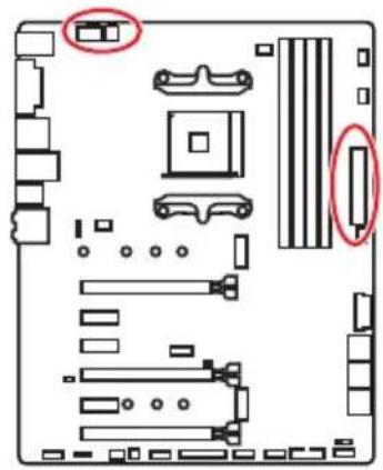
CPU_FAN1, PUMP_FAN1, SYS_FAN1~4: Fan Connectors
Fan connectors can be classified as PWM (Pulse Width Modulation) Mode or DC Mode. PWM Mode fan connectors provide constant 12V output and adjust fan speed with speed control signal. DC Mode fan connectors control fan speed by changing voltage. When you plug a 3-pin (Non-PWM) fan to a fan connector in PWM mode, the fan speed will always maintain at 100% , which might create a lot of noise. CPU_FAN1 and PUMP_FAN1 can automatically detect PWM and DC mode. You can follow the instruction below to adjust the fan connector to PWM or DC Mode.

Default Auto Mode fan connector
CPU_FAN1
You can switch between PWM mode and DC mode and adjust fan speed in BIOS > HARDWARE MONITOR.
Select PWM ,DC or Auto mode
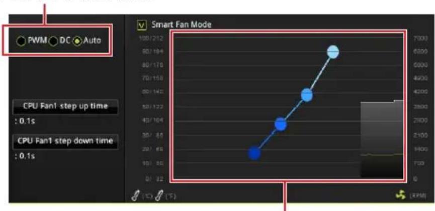
There are gradient points of the fan speed that allow you to adjust fan speed in relation to CPU temperature.

Important
Make sure fans are working properly after switching the PWM/ DC mode.
Pin definition of fan connectors
| PWM Mode pin definition | |||
| 1 G | round 2 +12V | ||
| 3 S | sense 4 Speed Control | Signal | |
| DC Mode pin definition | |||
| 1 | Ground 2 Voltage | Control | |
| 3 | Sense 4 NC | ||
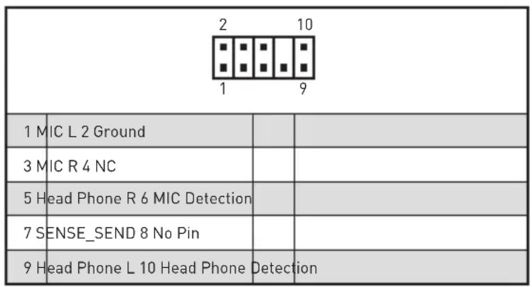
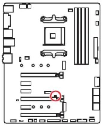
JAUD1: Front Audio Connector
This connector allows you to connect audio jacks on the front panel.

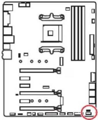
JCI1: Chassis Intrusion Connector
This connector allows you to connect the chassis intrusion switch cable.

Normal (default)

Trigger the chassis intrusion event
Using chassis intrusion detector
- Connect the JCI1 connector to the chassis intrusion switch/ sensor on the chassis.
- Close the chassis cover.
- Go to BIOS > Settings > Security > Chassis Intrusion Configuration.
- Set Chassis Intrusion to Enabled.
- Press F10 to save and exit and then press the Enter key to select Yes.
- Once the chassis cover is opened again, a warning message will be displayed on screen when the computer is turned on.
Resetting the chassis intrusion warning
- Go to BIOS > Settings > Security > Chassis Intrusion Configuration.
- Set Chassis Intrusion to Reset.
- Press F10 to save and exit and then press the Enter key to select Yes.
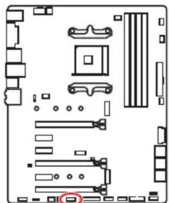
JFP1, JFP2: Front Panel Connectors
These connectors connect to the switches and LEDs on the front panel.
| JFP1 | |||
| 2 | 10 | ||
| 1 | 9 | ||
| 1 H | DD LED + 2 | Power LED + | |
| 3 H | DD LED - 4 | Power LED - | |
| 5 | Reset Switch 6 Power | Switch | |
| 7 | Reset Switch 8 Power | Switch | |
| 9 | Reserved | 10 | No Pin |
| JFP2 | 1 S | speaker - 2 Buzzer + | |
| 3 | Buzzer - | 4 | |
| Speaker + |
JTPM1: TPM Module Connector
This connector is for TPM (Trusted Platform Module). Please refer to the TPM security platform manual for more details and usages.
| 2 14 1 13 | |||
| 1 LPC Clock 2 3V Standby power | |||
| 3 LPC Reset 4 3.3V Power | |||
| 5 LPC address & data pin0 6 Serial IRQ | |||
| 7 LPC address & data pin1 8 5V Power | |||
| 9 LPC address & data pin2 10 No Pin | |||
| 11 LPC address & data pin3 12 Ground | |||
| 13 LPC Frame 14 Ground | |||
JCOM1: Serial Port Connector
This connector allows you to connect the optional serial port with bracket.
| 2 10 1 9 | |||
| 1 | D 2 SIN | ||
| 3 | SOUT 4 DTR | ||
| 5 | Ground 6 DSR | ||
| 7 | RTS 8 | CTS | |
| 9 | No | Pin | |
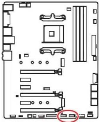
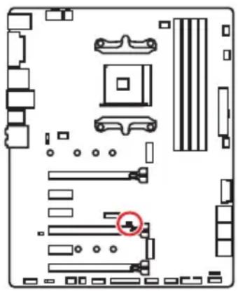
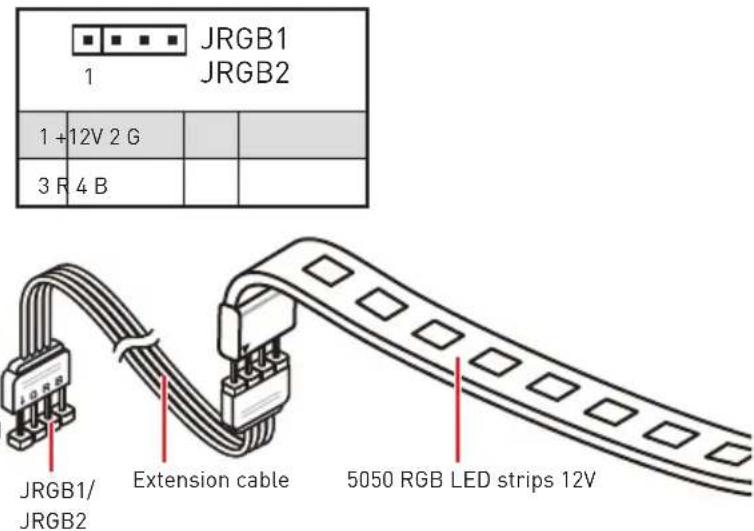
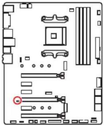
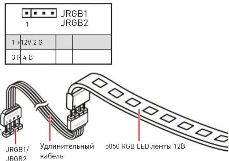
JRGB1, JRGB2: RGB LED Connectors
The JRGB1/JRGB2 connector allows you to connect the 5050 RGB LED strips 12V and AMD CPU cooler with RGB LED.

! Important
The JRGB1/JRGB2 connector supports 5050 RGB LED strips (12V/G/R/B) with the maximum power rating of 3A (12V).
Please keeping the LED strip shorter than 2 meters to prevent dimming.
Always turn off the power supply and unplug the power cord from the power outlet before installing or removing the RGB LED strip.
Please use MSI's software to control the extended LED strip.
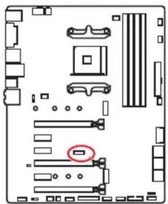
JBAT1: Clear CMOS (Reset BIOS) Jumper
There is CMOS memory onboard that is external powered from a battery located on the motherboard to save system configuration data. If you want to clear the system configuration, set the jumpers to clear the CMOS memory.

Keep Data
(default)

Clear CMOS/
Reset BIOS
Resetting BIOS to default values
- Power off the computer and unplug the power cord.
- Use a jumper cap to short JBAT1 for about 5-10 seconds.
- Remove the jumper cap from JBAT1.
- Plug the power cord and power on the computer.
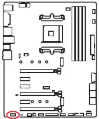
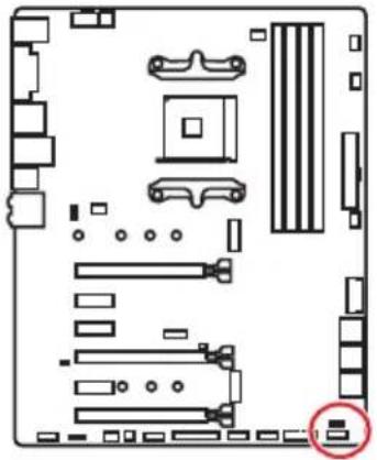
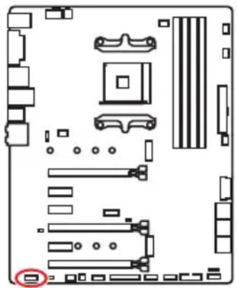
CLR_CMOS1: Clear CMOS Button
Power off your computer. Press and hold the Clear CMOS button for about 5-10 seconds to reset BIOS to default values.


Clear CMOS button
BIOS Setup
The default settings offer the optimal performance for system stability in normal conditions. You should always keep the default settings to avoid possible system damage or failure booting unless you are familiar with BIOS.
Important
BIOS items are continuously update for better system performance. Therefore, the description may be slightly different from the latest BIOS and should be for reference only. You could also refer to the HELP information panel for BIOS item description.
The pictures in this chapter are for reference only and may vary from the product you purchased.
Entering BIOS Setup
Press Delete key, when the Press DEL key to enter Setup Menu, F11 to enter Boot Menu message appears on the screen during the boot process.
Function key
F1: General Help
F2: Add/ Remove a favorite item
F3: Enter Favorites menu
F4: Enter CPU Specifications menu
F5: Enter Memory-Z menu
F6: Load optimized defaults
F7: Switch between Advanced mode and EZ mode
F8: Load Overclocking Profile
F9: Save Overclocking Profile
F10: Save Change and Reset*
F12: Take a screenshot and save it to USB flash drive (FAT/ FAT32 format only).
Ctrl+F: Enter Search page
- When you press F10, a confirmation window appears and it provides the modification information. Select between Yes or No to confirm your choice.
Resetting BIOS
You might need to restore the default BIOS setting to solve certain problems. There are several ways to reset BIOS:
- Go to BIOS and press F6 to load optimized defaults.
- Short the Clear CMOS jumper on the motherboard.

Important
Be sure the computer is off before clearing CMOS data. Please refer to the Clear CMOS jumper section for resetting BIOS.
Updating BIOS
Updating BIOS with M-FLASH
Before updating:
Please download the latest BIOS file that matches your motherboard model from MSI website. And then save the BIOS file into the USB flash drive.
Updating BIOS:
- Insert the USB flash drive that contains the update file into the computer.
- Press Ctrl+F5> key during POST.
- Click on Yes to reboot the system and enter the flash mode.
- Select a BIOS file to perform the BIOS update process.
- After the flashing process is 100% completed, the system will reboot automatically.
Updating the BIOS with Live Update 6
Before updating:
Make sure the LAN driver is already installed and the Internet connection is set properly.
Updating BIOS:
- Install and launch MSI LIVE UPDATE 6.
- Select BIOS Update.
- Click on Scan button.
- Click on Download icon to download and install the latest BIOS file.
- Click Next and choose In Windows mode. And then click Next and Start to start updating BIOS.
- After the flashing process is 100% completed, the system will restart automatically.
EZ Mode
At EZ mode, it provides the basic system information and allows you to configure the basic setting. To configure the advanced BIOS settings, please enter the Advanced Mode by pressing the Setup Mode switch or F7 function key.
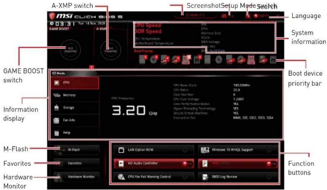
- GAME BOOST switch - click on it to toggle the GAME BOOST for OC.
Important
Please don't make any changes in OC menu and don't load defaults to keep the optimal performance and system stability after activating the GAME Boost function.
-
A-XMP switch (optional) - click on the inner circle to enable/ disable the A-XMP. Switch the outer circle to select the memory profile if any. This switch will only be available if the installed processor and memory modules support this function.
-
Setup Mode switch - press this tab or the F7 key to switch between Advanced mode and EZ mode.
-
Screenshot - click on this tab or the F12 key to take a screenshot and save it to USB flash drive (FAT/ FAT32 format only).
-
Search - click on this tab or the Ctrl+F keys and the search page will show. It allows you to search by BIOS item name, enter the item name to find the item listing. Move the mouse over a blank space and right click the mouse to exit search page.
Important
In search page, only the F6, F10 and F12 function keys are available.
-
Language - allows you to select the language of BIOS setup.
-
System information - shows the CPU/ DDR speed, CPU/ MB temperature, MB/ CPU type, memory size, CPU/ DDR voltage, BIOS version and build date.
-
Boot device priority bar - you can move the device icons to change the boot priority. The boot priority from high to low is left to right.
-
Information display - click on the CPU, Memory, Storage, Fan Info and Help buttons on left side to display related information.
- Function buttons - enable or disable the LAN Option ROM, HD audio controller, Window 10 WHQL Support, AHCI, RAID, CPU Fan Fail Warning Control and BIOS Log Review by clicking on their respective button.

Important
During windows setup, the RAID driver may be required and you can find the RAID driver in MSI Driver Disc.
You can use MSI SMART TOOL to build the Windows® installation drive that includes RAID driver.
If your system currently boots to M.2 SSD RAID and you delete the RAID volume in the EFI BIOS, your system will become un-bootable.
- M-Flash - click on this button to display the M-Flash menu that provides the way to update BIOS with a USB flash drive.
- Hardware Monitor - click on this button to display the Hardware Monitor menu that allows you to manually control the fan speed by percentage.
- Favorites - press the Favorites tab or the F3 key to enter Favorites menu. It allows you to create personal BIOS menu where you can save and access favorite/ frequently-used BIOS setting items.
- Default HomePage - allows you to select a BIOS menu (e.g. SETTINGS, OC...,etc) as the BIOS home page.
- Favorite1~5 - allows you to add the frequently-used/ favorite BIOS setting items in one page.
-
To add a BIOS item to a favorite page (Favorite 1~5)
-
Move the mouse over a BIOS item not only on BIOS menu but also on search page.
- Right-click or press F2 key.
- Choose a favorite page and click on OK.
To delete a BIOS item from favorite page
- Move the mouse over a BIOS item on favorite page (Favorite 1~5)
- Right-click or press F2 key.
- Choose Delete and click on OK.
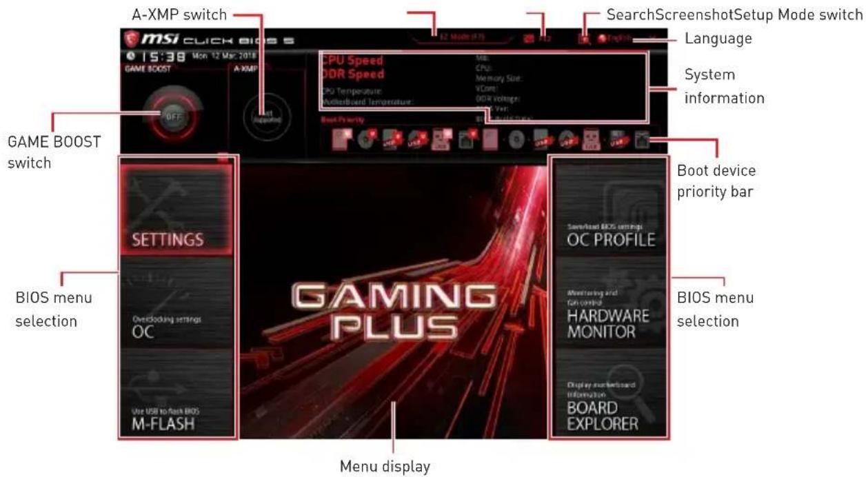
Advanced Mode
Press Setup Mode switch or F7 function key can switch between EZ Mode and Advanced Mode in BIOS setup.
-
GAME BOOST switch/ Setup Mode switch/ Screenshot/ Favorites/ Language/ System information/ Boot device priority bar - please refer to the descriptions of EZ Mode Overview section.
-
BIOS menu selection - the following options are available:
-
SETTINGS - allows you to specify the parameters for chipset and boot devices.
- OC - allows you to adjust the frequency and voltage. Increasing the frequency may get better performance.
- M-FLASH - provides the way to update BIOS with a USB flash drive.
- OC PROFILE - allows you to manage overclocking profiles.
- HARDWARE MONITOR - allows you to set the speeds of fans and monitor voltages of system.
-
BOARD EXPLORER - provides the information of installed devices on this motherboard.
-
Menu display - provides BIOS setting items and information to be configured.
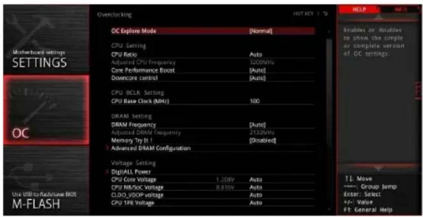
OC Menu
This menu is for advanced users who want to overclock the motherboard.
! Important
Overclocking your PC manually is only recommended for advanced users.
Overclocking is not guaranteed, and if done improperly, it could void your warranty or severely damage your hardware.
If you are unfamiliar with overclocking, we advise you to use GAME BOOST function for easy overclocking.
The BIOS items in OC menu will vary with the processor.
OC Explore Mode [Normal]
Enables or disables to show the normal or expert version of OC settings.
[Normal] Provides the regular OC settings in BIOS setup.
[Expert] Provides the advanced OC settings for OC expert to configure in BIOS setup.
Note: We use * as the symbol for the OC settings of Expert mode.
CPU Ratio [Auto]
Sets the CPU ratio that is used to determine CPU clock speed. This item can only be changed if the processor supports this function.
Core Performance Boost [Auto]
Enables or disables the Core Performance Boost (CPB). This item appears when the installed CPU supports this function.
Downcore Control [Auto] (optional)
Sets the number of processor cores to be used. This item appears when the installed CPU supports this function.
A-XMP [Disabled]
Please enable A-XMP or select a profile of memory module for overclocking the memory. This item will be available when the installed memory modules, processor and motherboard support this function.
DRAM Frequency [Auto]
Sets the DRAM frequency. Please note the overclocking behavior is not guaranteed.
Memory Try It ! [Disabled]
It can improve memory compatibility or performance by choosing optimized memory preset.
Memory Retry Count [5]
Sets counts for memory OC retrying. When memory OC has failed, setting this item as [5] will allow system to reboot 5 times with the same overclocked configuration. If overclocking has failed every time, the system will restore the defaults.
Advanced DRAM Configuration (optional)
Press Enter to enter the sub-menu. User can set the memory timing for each/ all memory channel. The system may become unstable or unbootable after changing memory timing. If it occurs, please clear the CMOS data and restore the default settings. (Refer to the Clear CMOS jumper/ button (optional) section to clear the CMOS data, and enter the BIOS to load the default settings.)
DigitALL Power
Press Enter to enter the sub-menu. Controls the digital powers related to CPU PWM.
CPU Loadline Calibration Control [Auto]
The CPU voltage will decrease proportionally according to CPU loading. Higher load-line calibration could get higher voltage and good overclocking performance, but increase the temperature of the CPU and VRM. If set to Auto, BIOS will configure this setting automatically.
CPU Over Voltage Protection [Auto]
Sets the voltage limit for CPU over-voltage protection. If set to Auto, BIOS will configure this setting automatically. Higher voltage provides less protection and may damage the system.
CPU Under Voltage Protection [Auto]
Sets the voltage limit for CPU under-voltage protection. If set to Auto, BIOS will configure this setting automatically. Higher voltage provides less protection and may damage the system.
CPU Over Current Protection [Auto]
- Sets the current limit for CPU over-current protection. If set to Auto, BIOS will configure this setting automatically.
[Auto] This setting will be configured automatically by BIOS.
[Enhanced] Extends the current range for over-current protection.
CPU Switching Frequency [Auto]
Sets the PWM working speed to stabilize CPU Core voltage and minimize ripple range. Increasing the PWM working speed will cause higher temperature of MOSFET. So please make sure a cooling solution is well-prepared for MOSFET before you increase the value. If set to Auto, BIOS will configure this setting automatically.
CPU VRM Over Temperature Protection [Auto]
Sets the temperature limit on CPU VRM for over-temperature protection. The CPU frequency may be throttled when CPU temperature over the specified temperature. If set to Auto, BIOS will configure this settings.
CPU Power Duty Control [Thermal Balance]
Sets the current of every VRM phase and the thermal conditions of every phase component.
[Thermal Balance] Maintains the VRM thermal balance.
[Current Balance] Maintains the current VRM balance.
CPU NB Loadline Calibration Control [Auto]
The CPU-NB voltage will decrease proportionally according to CPU-NB loading. Higher load-line calibration could get higher voltage and good overclocking performance, but increase the temperature. If set to Auto, BIOS will configure this setting automatically.
CPU NB Over Current Protection [Auto]
Sets the current limit for CPU-NB over-current protection. If set to Auto, BIOS will configure this setting automatically.
[Auto] This setting will be configured automatically by BIOS.
[Enhanced] Extends the current range for over-current protection.
CPU NB Switching Frequency [Auto]
Sets the PWM working speed to stabilize CPU-NB voltage and minimize ripple range. Increasing the PWM working speed will cause higher temperature of MOSFET. So please make sure a cooling solution is well-prepared for MOSFET before you increase the value. If set to Auto, BIOS will configure this setting automatically.
CPU NB Power Duty Control [Thermal Balance]
Sets the current of CPU-NB VRM phase and the thermal conditions of every phase component.
[Thermal Balance] Maintains the VRM thermal balance.
[Current Balance] Maintains the current VRM balance.
VR 12VIN OCP Expander [Auto]
Expands the limitation of VR Over Current Protection with 12V input voltage. The higher expanding value indicates less protection. Therefore, please adjust the current carefully if needed, or it may damage the CPU/VR MOS. If set to "Auto", BIOS will configure this setting automatically.
CPU Voltages control [Auto]
These options allow you to set the voltages related to CPU. If set to Auto, BIOS will set these voltages automatically or you can set it manually.
DRAM Voltages control [Auto]
These options allow you to set the voltages related to memory. If set to Auto, BIOS will set these voltages automatically or you can set it manually.
Memory Changed Detect [Enabled]*
Enables or disables the system to issue a warning message during boot when the memory has been replaced.
[Enabled] The system will issue a warning message during boot and then you have to load the default settings for new devices.
[Disabled] Disables this function and keeps the current BIOS settings.
CPU Specifications
Press Enter to enter the sub-menu. This sub-menu displays the information of installed CPU. You can also access this information menu at any time by pressing [F4]. Read only.
CPU Technology Support
Press Enter to enter the sub-menu. The sub-menu shows the key features of installed CPU. Read only.
MEMORY-Z
Press Enter to enter the sub-menu. This sub-menu displays all the settings and timings of installed memory. You can also access this information menu at any time by pressing [F5].
DIMMx Memory SPD
Press Enter to enter the sub-menu. The sub-menu displays the information of installed memory. Read only.
CPU Features
Press Enter to enter the sub-menu.
Simultaneous Multi-Threading [Enabled] (optional)
Enables/ disables the AMD Simultaneous Multi-Threading. This item appears when the installed CPU supports this technology.
Global C-state Control [Enabled] (optional)
Enables/ disables IO based C-state generation and DF C-states.
Opaque Control [Auto] (optional)
Enables/ disables Orcache. Orcache stores recently decode instruction to save the decoding time when the instruction is repeated. And ist may increase the CPU performance and reduce the power consumption slightly.
IOMMU Mode (optional)
Enables/disables the I0MMU (I/O Memory Management Unit) for I/O Virtualization.
Spread Spectrum (optional)
This function reduces the EMI (Electromagnetic Interference) generated by modulating clock generator pulses.
[Enabled] Enables the spread spectrum function to reduce the EMI (Electromagnetic Interference) problem.
[Disabled] Enhances the overclocking ability of CPU Base clock.
Important
If you do not have any EMI problem, leave the setting at [Disabled] for optimal system stability and performance. But if you are plagued by EMI, select the value of Spread Spectrum for EMI reduction.
The greater the Spread Spectrum value is, the greater the EMI is reduced, and the system will become less stable. For the most suitable Spread Spectrum value, please consult your local EMI regulation.
Remember to disable Spread Spectrum if you are overclocking because even a slight jitter can introduce a temporary boost in clock speed which may just cause your overclocked processor to lock up.
Relaxed EDC throttling [Auto] (optional)
Relaxed EDC throttling reduces the amount of time the processor will throttle the cores.
[Auto] AMD's recommendation
[Enabled] Reduce the amount of time the processor will throttle.
[Disabled] Part-specific EDC throttling protection enabled.
AMD Cool'n'Quiet [Enabled]
The Cool'n' Quiet technology can effectively and dynamically lower CPU speed and power consumption.
SVM Mode [Disabled]
Enables/ disables the AMD SVM (Secure Virtual Machine) Mode.
BIOS PSP Support [Enabled] (optional)
Enables/ disables the BIOS PSP support. It manages PSP sub-item including all C2P/P2C mailbox, Secure S3, fTPM support.
Power Supply Idle Control [Auto] (optional)
It allows you to select the power-saving control mode for CPU when all cores are in a non-CO state. If set to Auto, BIOS will configure this settings.
Software Description
Installing Windows® 10
- Power on the computer.
- Insert the Windows 10 disc into your optical drive.
- Press the Restart button on the computer case.
- Press F11 key during the computer POST (Power-On Self Test) to get into Boot Menu.
- Select your optical drive from the Boot Menu.
- Press any key when screen shows Press any key to boot from CD or DVD... message.
- Follow the instructions on the screen to install Windows 10.
Installing Drivers
- Start up your computer in Windows ③ 10.
- Insert MSI Driver Disc into your optical drive.
- The installer will automatically appear and it will find and list all necessary drivers.
- Click Install button.
- The software installation will then be in progress, after it has finished it will prompt you to restart.
- Click OK button to finish.
- Restart your computer.
Installing Utilities
Before you install utilities, you must complete drivers installation.
- Insert MSI Driver Disc into your optical drive.
- The installer will automatically appear.
- Click Utilities tab.
- Select the utilities you want to install.
- Click Install button.
- The utilities installation will then be in progress, after it has finished it will prompt you to restart.
- Click OK button to finish.
- Restart your computer.
NOTE
Inhalt
SATA1~6: SATA 6Gb/s Anschlüsse
JUSB1~2: USB 2.0 Anschlüsse
JUSB3~4: USB 3.1 Gen1 Anschlüsse
| JUSB3 | 10 JUSB4 | ||
| 1 Power 11 USB2.0+ | |||
| 2 USB3_RX_DN 12 USB2.0- | |||
| 3 USB3_RX_DP 13 Ground | |||
| 4 Ground | 14 | USB3_TX_C_DP | |
| 5 USB3_TX_C_DN | 15 | USB3_TX_C_DN | |
| 6 USB3_TX_C_DP | 16 Ground | ||
| 7 Ground | 17 | USB3_RX_DP | |
| 8 USB2.0- | 18 | USB3_RX_DN | |
| 9 USB2.0+ | 19 | Power | |
| 10 NC | 20 | No Pin | |
Wichtig
JFP1, JFP2: Frontpanel-Anschlüsse
| JFP2 | 1 S | speaker - 2 Buzzer + | |
| 3 | Buzzer - | 4 | |
| Speaker + |
JRGB1, JRGB2: RGB LED Anschlüsse
DRAM Frequency [Auto]
Memory Retry Count [5]
CPU Voltages control [Auto]
DRAM Voltages control [Auto]
CPU Technology Support
Relaxed EDC throttling [Auto] (optional)
Power Supply Idle Control [Auto] (optional)
PCI_E1~6: Slots d extension PCIe 14
M2_1~2: Slots M.2 (Touche M) 16
| JUSB3 | 10 JUSB4 | ||
| 1 Power 11 USB2.0+ | |||
| 2 USB3_RX_DN 12 USB2.0- | |||
| 3 USB3_RX_DP 13 | Ground | ||
| 4 | Ground | 14 | USB3_TX_C_DP |
| 5 | USB3_TX_C_DN | 15 | USB3_TX_C_DN |
| 6 | USB3_TX_C_DP | 16 | Ground |
| 7 | Ground | 17 | USB3_RX_DP |
| 8 | USB2.0- | 18 | USB3_RX_DN |
| 9 | USB2.0+ | 19 | Power |
| 10 | NC | 20 | No Pin |
Important
| JFP2 | 1 S | speaker - 2 Buzzer + | |
| 3 | Buzzer - | 4 | |
| Speaker + |
DRAM Frequency [Auto]
Memory Retry Count [5]
CPU Voltages control [Auto]
DRAM Voltages control [Auto]
CPU Technology Support
KomnoheTbMaTepuHckoI PaTbI 11
Ppoecccopnb cokeT 12
CnotbDIMM 13
PCI_E1~6: CnotbI paCunpeHnPAle 14
M2_1~2:Pa3bem M.2 (Klouy M) 16
SATA1~6:Pa3beMbI SATA 6Γ6/c 17
JLPT1:Pa3bemnapaannelbHoro npota. 17
CPU_PWR1,CPU_PWR2,ATX_PWR1:Pa3bemblnTaHna 18
JUSB1~2:Pa3beMbI USB 2.0. 19
JUSB3-4:Pa3beMbI USB 3.1 Gen1 19
CPU_FAN1, PUMP_FAN1, SYS_FAN1~4: Pa3bembl BeHTnlaTopoB 20
JAUD1:Pa3bem ayndno nepedneynanei 21
JC11:Pa3bEm DaTUnKa OTKpbITnK Kopnyca 21
JFP1, JFP2: Pa3bembl nepednei nahei 22
JTPM1:Pa3bemMoDyJIa TPM 22
JCOM1:Pa3bem nocneioBaTeIbHoro npTa 23
JRGB1, JRGB2: Pa3beM RGB LED 23
JBAT1:Джампег оочткданьх CMOS [C6pocBIOS] 24
CLR_CMOS1:KhoNka ouNCTKn daHbIX CMOS 24
HacrpoikaBIOS 25
Bxod B HacTropon BiOS 25
C6pocBIOS 26
06HOBJIeHneBIOS 26
PexnEM EZ 27
Pexnmpa3roHa 29
MeHIOOC 30
Onncahne nporpaMMHoro oecneuehna 35
YcTaHOBkaWindows 10. 35
UcTaHOBka dpaIbepOB 35
YCTaHOBka yTnIIT 35
He onyckaIte Bo3neIcTBnHa MaTePNHckayIO nlaTy BbICOKO BnaXHOCTN.
-
IpepeTem KaK NODKIOUHTb 6IOK NITAHN KOMNbIOTepa K 3JIeKTpNUeCKO np03eTke y6eHNTecb, YTO HAprrXeHne 3JIeKTPOcETn COOTBeTCTByeT HaPrrXeHHU, yKa3aHHOMy Ha 6Ioke NITAHN.
-
PacnoIaraiTe shypr nHTaHn TaK, yTO6bHa Hero He MoTn HaCTyNTb JIOdN. He cTaBbTe Ha wHypr nHTaHn HnKaKnx PpeMetOB.
Heo6xOIMO yuHTbBaTb BCE npedoctepekeHn npedynpexKeHnya3aHHbIe Ha MaTePHNCKo nnate.
- PnB03HKnHOBeHnn IIO6oN n3 nepeuNCJIeHHbIX HnXe CNTyaIIN O6paTntEcB B cepBnCHbI ueHTp dIy npOBepKm MaTePNHCKO nnAaTbl:
-Пonaдане КИДКОCTN BHyTpь KOMNBIOTepa.
MaTePnHcka NlaTa NoBBeprIacb BO3DeIcTBIO BnaI.
MaTePnHcka nnata He pa6oTaet OJIKHbIM 6pa3OM nIIN HeBO3MOXHO HanaNTbe pa6OBy B COOTBETCTBUN C pyKOBoDCTBOM NOIb3OBaTeJIa.
-
MatepeHncka nlaT a noJyUna noBpeKdEHH np naDeHH.
-
MaTePnHcKaI pIaTa IMeET ABHbIe npI3HaKn NOBpeKdEHHa.
-
He xpaHnTe MaTePunHckyo nnAty B MeCTax C TeMnePaTypoB Bblwe 60^ [140 F], TaK KaK 3TO MoKeT npUBeCTn K ee NOBpeXdeHnIO.the motherboard.
TexHnueckne xapaKTepeNCTnKN
PpOdoJIkeHnE Ha cIeMyoUeNcTpaHnue
PpOdoJIxKeHnE c npeIbIyUeJ cTpaHnUcI
ABTOMaTnueckoe BCnIbIbAIOoee dnaIanoROBoe OKHO
Pn noKnHueHn ycTpoNCTBa K pa3bemy ayDNo NOBNTc DnaJNOBOE OKHO C npocboon noTBePntb noKnHueHHoe ycTPONCTBO.
KaKdbi pa3bem COOTBeTCTByeTe rO HAcTpOuKam No yMOnUaHnIO, KaK NOKa3aHO Ha cIeNyUoSe CTpaHnCe.

IopKIOUeHne HayuHKnOB uMknpoOHa
KoMnoHentbI MaTePnHcKoI nlaTbI
Пюцeccорный сокет
Пюцeccop AM4
HaNoBepxHocTn npoecccopa AM4
mMeetc30JIoTOy TpeyroIbHNK
dIy npaBnIbHOY UCTaHOBKn
npoecccopa OTHOCHTeNbHO
npoecccopHOrO COKeTa
MaTePNHCKo NpAToB.30JIoTOy
TpeyroIbHNk YKa3bIBaET Ha
KOHTAKT 1.

BHHMaHHe!
13-3a ocobehnocte apxntektypb npoueccopo AM4, 3ameha npouecoppa MoKet npnbectn K c6pocy Hactpoek B10S do 3nauehen no ymonuaHIO.
IpeyctaHOBko nn 3ameHOn npouecoppa, Heo6xOIMO OTKJIIOHTb Ka6eJb nHTAHn.
Pn yctahOBke npouecoppa o63aTeIbHO yCTAHOBnTE npoueccopHbIKyIep.KyIep, npedcTabraIooi co6oN cnCTemy OxlanKeHnnpoueccopa, npedotBpaaet neperpeB n obecneuINBaET cTaNbHyO pa60Ty cnCTEmbl.
RepeB BKNIOUeHHeM CnCTeMbI NpOBepbTe RepMeTNUHOCb COeINHeHnMa MeKdy npOueCCOPOM n paDnATOpOM.
NepereB MoKet npuBeCTn K cepbe3Homy NOBpeJdeHIO pOueccopa n MaTePNHcKO nnatb. Bcerda npOBepaTE pa6OTocNoC6HocTb BeHTnIaTopa n 3aunTbI npoueCCopa ot nepereBa. Pn yctahOBKe KyIepa HaHeCtPePoBHn CNOI TepmonactBI (nn TepMOJeHTy) Ha KpbIshky UCTaHOBHeHHOro pOueCCopa dJIyUyuWeHn TeTTonepeDaun.
EcnBbI npno6peHn OTdIeNbHO npoceccop n npoceccopHny KJep, noDpo6hoe ONscaHne yCTaHOBKn CM. B DOKymeHTaunn B daHHOMy KJepy.
aHaHna CnCTeMHra Pnata pa3pa6oTaHa C yueTOM Bo3MOxHOCTn ee «pa3roHa>. Ipeed BblONHeHneM pa3roHa CNCTeMbI y6eHTecb B TOM, qTO BCE KOMnoHEtbl CNCTeMbI CMORYT erO BblEepKaTb. IpOn3BOJntelb He peKOMeHnyet NcNoB3OBaTb NapaMeTpbl, BblOJaUe 3a npedeJIbTexHnuecknx XapaKTepuCTNK UcTPOiCTB. IapaHTnRA Ml He pacnpocTpahReTcH Na NobpeJeHnru n DpyrNe BO3MOxHbIe NocIeDCTBnR HeHaJLekaSe 3KcNlyatauIN O6OpyDoBaHnI.
CnotbIDIMM

PekomeHdaaunno yctahOBKe moyJe namrTn


BHMaHne!
Bcerda yctaHaBnBaIte MoyIb namrtn Chaayana B CLOT DIMMA2.
B CB83n CO CneuФнкои nCnoIb3ObaHna pecypcoB uNcTeTa,doCTyHHbI O6bEm namrTu BydET HEMHO MeHbSe, yemΦaKTUyeCKn yCTaHOBJIeHHbI.
Ha ochobe xapaKTepeNtuk npoueccopa, pekOMeHnyeTcyaTaHaBnVBaTb HapjKeHne Ha namrtn DIMM meHee 1.35 B. 3TO no3BOJNT 3aunTntb npouecop.
Hekotopbme Modynn namrtn npn pa3roHe moryt pa60TaTb Ha qactotax Hnke 3aBleHHo npn3BOJnteIem, NocKOBky BbICTabIeMaJn naMrtu qactota 3aBncT OT uHOpMaun, 3aIncAHo B SPD (Serial Presence Detect). 3aInte B BIOS n Bbl6epnte onuIO DRAM Frequency, yTO6bl yCTaHOBTb 3aBneHHyIO nn 6Oone BbICOKyIO qactOTy.
Pn yctahOBKe namrBo Bce Cnotb, a TaKke npue pa3roHe, peKomeHdyeTcNcNoB3OBAt6Oone 0f0fKeKTHBHyU CnCTemy OxnaXdEHHaNamrTu.
OBMECTUMOCTb nCTa6nIbHOCTb pa60tby yCTaHOBLeHHORo MOyJI naMAYn pN pa3ROHe 3aBnCnT OT yCTaHOBLeHHORo IPOeCCopa n dpynx yCTpOInCTB.
3-3a orpaHueHn oHnuaJIbHOc CneuNfKaun npoueccopa AM4/ KOHTpOJIePa nAMrT, MoyIIN nAMrT MOrY T pa6oTaTb Ha YacToTAX Hnke 3aBHeHHo npOn3BOJnteIem npn HacPoiKax NO yMOJauHIO. OonoHnTeJIbHyU INHOpMaIIO O COBMeCTUMbIX MoyIaX nAMrT N MoxHo HaHTn Ha Be6-caTe www.msi.com.
- BbIKpyTnte cToiKy IJI KpeIeHnM.2 MoyJN n3 MaTePNHcKoI PAtbl.
- 3aKpyTnTe cToiKy
IJa KpeIeHnA M.2
MOyJIb B NOxOJaUe
OTBepCTne, B
COOTBeTCTBnC dINHO
BaJero M.2 SSD. - BcTaBbTe M.2 SSD b pa3bem M.2 noJ yIOM 30 rpaDycoB.
4.3aKpenTe M.2 SSDcPOMObIO npnlaeraMOro BnHTa 1M.2.
SATA1~6: Pa3beMbI SATA 6Γ6/c
3TN pa3bembl npedctablaHOT co6o nHTeppechbIe nopTbSATA 6Γ6/c. K KaKdOMy NOpTy MOxHO NOkJIIOuHTb OJHO yCTpOuCTBO SATA.
!Вниманue!
HopT SATA1 6yndet Heioctynen npu yctaHOBKe SATA M.2 SSD B pa3beme M2_2.
36eraIte neperu6OB ka6eRA SATA noI npMbIM yrnom. B npOTNBOM cnUyae, BO3MOXHa nOTepeJaHHbIX npn nepeDaue.
Ka6eHn SATA Ochauhebl OUNHaKObIMN KOHNKeTOpAMn C ObENxCtOPOH. OHaKo, IJIa 3KOHOMu 3aHUMaEMOr npocTpaHCTBa K MaTePNHcKoI PNaTe peKoMeHdyetcnoKnUoyaTb NLOCKn pa3beM.
JLPT1: Pa3bem napaJIeIbHOro nopTa
AnHHbI pa3bem No3BOJareT NOdkJIIOUHTb npaJIeJIbHbI NOPr,pa3MeueHHbI Ha BHeuHem 6paKeTe.

| 2 1 26 | |||||
| 1 | STB# 2 AFD# 3 PRND0 | ||||
| 4 | ERR# 5 PRND1 6 PINT# | ||||
| 7 | PRND2 8 LPT SLIN# 9 PRND3 | ||||
| 10 | Ground | 11 | PRND4 | 12 | Ground |
| 13 | PRND5 | 14 | Ground | 15 | PRND6 |
| 16 | Ground | 17 | PRND7 | 18 | Ground |
| 19 | ACK# 20 Ground | 21 BUSY | |||
| 22 | Ground | 23 | PE | 24 | Ground |
| 25 | SLCT | 26 | No Pin | ||
CPU_PWR1, CPU_PWR2, ATX_PWR1: Pa3bemblnTaHnA
DaHHbIe pa3beMbI npedHa3HaueHbI nla noKnIOUeyHn6loka nHTaHn ATX.
| 8 4 5 CPU_PWR1 | |||
| 1 Ground 5 | +12V | ||
| 2 Ground 6 | +12V | ||
| 3 Ground 7 | +12V | ||
| 4 Ground 8 | +12V | ||
| CPU_PWR2 | |||
| 1 Ground 3 | +12V | ||
| 2 Ground 4 | +12V | ||
| 12 24 ATX_PWR1 1 13 | 1 +3 .3V 13 +3.3V | ||
| 2 +3 .3V 14 -12V | |||
| 3 Ground 15 Ground | |||
| 4 +5V 16 PS-ON# | |||
| 5 Ground 17 Ground | |||
| 6 +5V 18 Ground | |||
| 7 Ground 19 Ground | |||
| 8 PWR OK 20 Res | |||
| 9 5VSB 21 +5V | |||
| 10 +12V 22 +5V | |||
| 11 +12V 23 +5V | |||
| 12 +3.3V 24 Ground |

BHHMaHHe!
IJIy oecneueHn cta6nblho pa60tbcntemHO nnatb npOBepbTe HAdexKHOCTb NOkNIOUeHn Bcex Ka6ene NHTAHN K 6NOKy NNTAHN ATX.
JUSB1~2:Pa3beMbl USB 2.0
DaHHbIe pa3beMbI npedHa3HaueHbI dJI NOdkJIOUeHn IOpTOB USB 2.0 Ha nepeHHe nAHeN.

| 2 10 1 9 | |||
| 1 | VCC | 2 | VCC |
| 3 USB0-4 | USB1- | ||
| 5 USB0+6 | USB1+ | ||
| 7 Ground 8 | Ground | ||
| 9 No Pin | 10 | NC | |

BHHMaHHe!
- TomHnte, yTO BO u36ekahne NOBpeKdEHN, Heo6xoNMO npaBnBHO noDKJIIOuATb KOHTaKTbI VCC n 3eMn.
-ДяТOrO,ЧTo6bIЗapdntbВaW iPAd,iPhone n iPod uepe3 nopTbI USB, noKanyuNCTa,yctahOBnTe yTuNtY MSIP SUPER CHARGER.
JUSB3~4: Pa3beMBI USB 3.1 Gen1
| JUSB3 | 10 JUSB4 | ||
| 1 Power 11 USB2.0+ | |||
| 2 USB3_RX_DN 12 USB2.0- | |||
| 3 USB3_RX_DP 13 Ground | |||
| 4 Ground 14 | USB3_TX_C_DP | ||
| 5 | USB3_TX_C_DN | 15 | USB3_TX_C_DN |
| 6 | USB3_TX_C_DP | 16 Ground | |
| 7 Ground 17 | USB3_RX_DP | ||
| 8 | USB2.0- | 18 | USB3_RX_DN |
| 9 | USB2.0+ | 19 | Power |
| 10 | NC | 20 | No Pin |

BHHMaHHe!
POMHnTe,TO BO
N36eKaHne NOBpeKdEHN,
Heo6XoJMo IpaBnIbHO
IOaKnHouaTb KOHTaKTbI
NTaHnN n 3emn.
CPU_FAN1, PUMP_FAN1, SYS_FAN1~4: Pa3bembl BeHTnJIrTOPOB
Pa3bembl BeHTnIaTOPOB MOxHO pa3dJIHTb Ha Db TUNa: c PWM (PulseWidth Modulation) ynpabLeHnEM u npabLeHnEM NOCToHHbIM TOKOM. Pa3bembl BeHTnIaTOPOB C PWM ynpabLeHnEM IMeOT KOtAKT C NOCToHHbIM HapJKeHnEM 12B, a TAKKc KoHTaKT C CNrHaLOM ynpabLeHnRA CKOpOCTbIO BpaUeHnA. UnpabLeHnECKOPoCTbIO BPAuSeHnBAENTNIArTOPOB C ynpabLeHnEM NOCToHHbIM TOKOM, OcyuEcTBJIaERcYpe3 COOTBeTCByUOUsne pa3bEmbl NytEm NImMeHnBAHNHbI HApJKeHnA. IOnTOMy, pni NpOKJIuOyeHnn 3-x KOtAKTHOrO (NonPWM) BeHTnIaTOPa K pa3bemy dJa BeHTnIaTOPa PWM, cKOpocTb BeHTnIaTOPa Bcerda 6ydt MaKcMaJIbHo. Pa60ta Takoro BeHTnlaTopa MoXET OKa3aTbcra DOCTaTOH NoMHO. CPU_FAN1 n PUMP_FAN1 MoryT ABOTMAtuYeCKn ONpeJeITb peKIM pa60tb BeHTnIaTOPa - PWM nIn DC. Jn HAcTpOuKn peKIma pa60tb BeHTnIaTOPa BpyHyIO (PWM nIn DC), cNeDuTe yKa3aHnAm HnKe.
Pa3bem BeHTnIaTopa c aBTOMaTHueckm ynpabLeHHeM no yMOJIaHnIO

Pa3bem BeHTnIaTopa C PWM ynpabJeHneM no yMoJIuHaHIO

PUMP_FAN1
Pa3bem BeHTnIaTopa C ynpabIeHneM NOCTOHHbIM TOKOM NO yMOJUaHIO

SYS_FAN1/ SYS_FAN3/ SYS_FAN4

SYS_FAN2
IpeeknueHne peKmOB pa60tbi nCKOpocTn Bpaune HBeHTnJIaTopa
B MeHIO BIOS > HARDWARE MONITOR Bbl MoKeTe Bbl6paTb peKIM pa60Tb BeHTnlaTopa: PWM nnn DC n HaCtpoNTb erO ckopoCTb BpaueHn.
Bb6epnte pekm PWM, DC nAuto
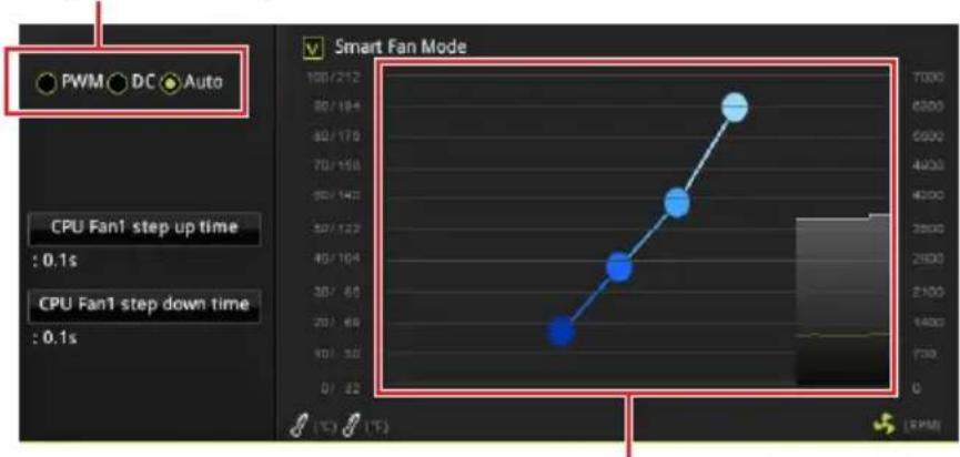
Bbl moKeTe peryInpoBaTb ckOpocTb BpaSeHnBeHTnIaTopa B 3aBncmOCTn OT TempeatpybI npoueccopa NyTem N3MeHeHn PNOJKeHn rpaJeHTbIX ToyeK.
! BhmamHe!
Y6eHntecb, yTO BeHTnlaTOpbl pa6ToIOT npaBnIbHO nOcne BbIbopa peKIma PWM/ DC.
Ha3haueHne KOHTaKTOB pa3bema IJI NOkIIOUeHnBEHTnIaTopa
| Ha3naчениkoNTaKToB pa3bema污染防治PwM | |||
| 1 Ground 2 +12V | |||
| 3 Sense 4 Speed C ontrol | Signal | ||
| Ha3naчениkoNTaKTOB pa3bema干嘛peЖима DC | |||
| 1 G | round 2 Voltage | Control | |
| 3 S | ense 4 NC | ||
JAUD1: Pa3bem aydno nepednei naheIi
DaHHb pa3bem npedHa3HaueH IJI NOdkIIOUeHnayuOpa3bEmOB nepeHne HnaHeN.
JCI1: Pa3bem daTUnka OTKpbITnKopnyca
K ətomy pa3bemy nocklouaetcra ka6elb ot daTnka oTkpbItna Kopnyca.


IcnoIb3OBAHne daTUnKa OTKpbITnK KopnyCa
- Пдклioчnte дaтун OK Крьтma К ра зему JCI1.
- 3akpoIte KpbIuKy Kopnyca.
- Bovinte BV BIOS > Settings > Security > Chassis Intrusion Configuration.
- YCTaHOBnTe Chassis Intrusion B Enabled.
- HaxMMTe KlaBnUy F10, yTo6bl coXpaHnTb HaCTpoN N BblTN, a 3aTEM HaxMMTe KlaBnUy Enter, yTo6bl Bbl6paTb Yes.
- Пи OTкрытпи Корпуca на за Кране 6удET NOЯВляТьСЯ пpeДупрждюшee coo6шени кждь pa3 рпв BKЛIOчЕни KOMMbЮТepa.
C6poc coo6eHn o6 otKpbITn Kopnyca
- BoiDnTeB BIOS > Settings > Security > Chassis Intrusion Configuration.
- BbIepeuTe Chassis Intrusion, Reset.
- HaxMMTe KlaBnUy F10, yTo6bl coXpaHnTb HaCTpoN N BblTN, a 3aTEM HaxMMTe KlaBnUy Enter, yTo6bl Bbl6paTb Yes.
JFP1, JFP2: Pa3bembl nepeDnei naHeJI
3Tu pa3bembl Cnykata NIOKLOUeHn KHOJOK n CBETOINOHBIX INDkaTOPOB, paONoJKeHHbIX Ha nepeDHei naHeJI.
| JFP1 | |||
| 2 | 10 | ||
| 1 | 9 | ||
| 1 H | DD LED + 2 | Power LED + | |
| 3 H | DD LED - 4 | Power LED - | |
| 5 | Reset Switch 6 Power | Switch | |
| 7 | Reset Switch 8 Power | Switch | |
| 9 | Reserved | 10 | No Pin |
| JFP2 | 1 S | speaker - 2 Buzzer + | |
| 3 | Buzzer - | 4 | |
| Speaker + |
JTPM1: Pa3bem moулТPM
daHbI pa3bem nCnoB3yeTcA IJI NODKIOUeHnMoDyIa TPM (Trusted Platform Module). OOnOHnTeNbHbIe CBeDeHn CM. B ONICAHN MoDyIa TPM.
| 2 14 1 13 | |||
| 1 LPC Clock 2 3V Standby power | |||
| 3 LPC Reset 4 3.3V Power | |||
| 5 LPC address & data pin0 6 Serial IRQ | |||
| 7 LPC address & data pin1 8 5V Power | |||
| 9 LPC address & data pin2 10 No Pin | |||
| 11 LPC address & data pin3 12 Ground | |||
| 13 LPC Frame 14 Ground | |||
JCOM1: Pa3bem nocleobateIbHoro nopTa
DaHHbI pa3bem N03BOJIaER T NOKJIHOHTb NOCJeIOBaTeJIbHbI IOpT, pa3MeeHHbI Ha BHeUHem 6paKeTe.

| 2 10 1 9 | |||
| 1 D | D 2 SIN | ||
| 3 SOUT 4 DTR | |||
| 5 Ground 6 DSR | |||
| 7 RTS 8 CTS | |||
| 9 | RI 10 | No | Pin |
JRGB1, JRGB2: Pa3bem RGB LED
Pa3bem JRGB1/JRGB2 npedHa3NaueH nIe NOKJIIOUeHn CBeTOINOHBIX JeHT 5050 RGB 12B u Kjlepa npoceccopa AMD c RGB cBeToNOHOI NOcBETKOJ.

BHHMaHHe!
Pa3bem JRGB1/JRGB2 noIeepKnBaet noKnIoueHne 5050 RGB cBeToIONoHbIX JeHT (12B/G/R/B) c MoUHOCTbIO 3A (12B).
6paTne BnMaHHe, YTO nnHa JeHT OJxHa 6bItb He 6Oone 2 MeTpOB, HNaYe npKocTb CBeueHna 6yTe NaTaB.
Hepa yctahOBko nn 3ameHO CBeToNDnHbIX nHT RGB, Heo6xOmo NOHOCtbIO OecTOUYtB CNCTemy N OTKNIouHTb Ka6JIb NTaHnI.
CnOJIb3yIte yTUNHTy MSI@ IЯ ynpaBHeHra ydINHHTeHBIMn CBETODIOHbIMN JeHTAMN.
Ctrl+F:BxOДВCTpaHnUynoncka
DRAM Frequency [Auto]
YCTAHOBKa YACTOTbI NAMrT DRAM. O6paTnte BHHMaHHe, YTO BO3MOXHOCTb ycNeuHoro pa3roHa He rapaHTnpyeTc.
Memory Try It ! [Disabled]
I03BOJnEYnyuWntb COBMeCTHMOCTb namrTu IN pOn3BOJNTeJIbHOCTb, nyTeM Bb6opa Han6Oone ONTImaJIbHoro npeceta.
Memory Retry Count [5]
YctaHabnBaet KOINueCTBO NONbITOK pa3roHa namrTn. Pnp HeydauHOM pa3roHe, YcTaHOBka 3HaueHna DaHHoro NyHKta B [5], No3BoJraTe Npe3arpy3ntb CnCTeMy 5 pa3 B Toi Je pa3orHaHHo KOnΦnrgpaun. Pnp HeydauHo NOnbITke pa3roHa, NapaMeTpbl CnCTeMbI BydUT BOCCTaHOBJIeHbI NO yMOJIuaHIO.
Advanced DRAM Configuration (onznoHaIbHo)
HaKmTe Enter IJI BxOaB NOJMeHIO. IOnb3OBaTeIb MoKeT HAcTpOHT TaMmHrI JI KAKDOrO KaHana NaMaTn.CNCTema MOKeT pa6OTaTB HeCTaBnBHO IIN He 3aRpyKaTbCnOcNe N3MeHeHnTaMnHROB NaMaTn.EcII CNCTema pa6OTAe HcTa6BnBHO, POXaLyNCTa, OUnCTnte DaHHbIe CMOS n BOCCTaHOBnTE HAcTPOkN IO yMOJUAnHIO. (CM. Nepembyka OUnCTKn DaHHbIX CMOS/pa3dEKN KONKn IJIy OUnCTKn DaHHbIX CMOS n BXoB B BIOS, YTO6bl 3aRpy3NTb HAcTPOkN IO yMOJUAnHIO.)
DigitALL Power
HaKmTe Enter IJIy BXOa B NOMeHIO. FyHKUrypabIeT cIeYMaN NITaHn, CB3aHHbIMc PwM npouecoppa.
CPU Loadline Calibration Control [Auto]
HaipjxHe Ha npoueccope yMeHbIaetc npOpOpunHO, B 3aBnCmOCTn O erO 3arpy3kn. NobIeHne 3NaueHnlaod-line Calibration npINBOuNT K NOBIIeHnIO HaipjxKeHn I npOn3BOUInTeJbHOCTn npN pa3roHe, Ho n YBeJIuHBAeT Tempeatypy npouecoppa n VRM. PnpYcTaHOBke B Auto, BIOS yCTaHOBNT daHHbI napaMeTp aBTOMaTnueckn.
CPU Over Voltage Protection [Auto]
YctaHabnBaet BepxHIOI rpaHnCy MaKcMaIbHOrO HapRjKeHnA Jn3aunTbi Ipoueccopa O T NOBbIeHHoro HapRjKeHn. Ecnn YcTaHOBJeHO Auto, BIOS ABTomatNueckn HAcTpON 3OT npaMeTp. Yem Bblwe 3HaueHne, Tem HnJke CTeneHb 3aunTbl N Bblwe BepoarTHOCTb BblOda CNCTeMbI N3 CTPoR.
CPU Under Voltage Protection [Auto]
YctaHabINBaet HxKHOIgpaHnUy HapJxHnI JI3aunTbI npOeCCopa OT NOHXKeHHOro HapJxHnI. Ecnn YcTaHOBLeHo Auto, BIOS aBTOMaTnueckn HAcTpont 3TOT napamTp. Yem BblIe 3NaueHne, TEm HxJce CTenEh 3aunTbI N BblIe BepoAHTHOCTb BblOda CnCTeMbI n3 CTPOr.
CPU Over Current Protection [Auto]
YcTaHaBnBaet OrpaHnueHne NO MaKcImaJbHOMy TOKy dJa 3aunTbi npoeccopa. Ppn yctaHBke B Auto, BIOS aBTOMaTnueckn HacTpont 3TOT napameTp.
[Auto] ΘOT napametp 6ydt Hactpoeh ABTomatnueckn C NOMOuBIO BIOS.
[Enhanced] Pacwnprer opranuene no TOKy ot neperpy3kn no TOKy.
CPU Switching Frequency [Auto]
UcTaHabJIINBaETCKOpocTbpa60TbPWMDIaCTaBn3aunHaIpaJKeHnaIpa
IpoueccopaMHNmN3aunDnana3oHaNyIbcaun.YBeJIuHeHne pa6Oeu
yactotbIPWM npIBODNTK CnIbHomy HarpReBy MOSFET. Ipeed tem kaK
yBeJIuHTb 3NaueHne y6eInTeCb, YTO oxJaXdEHeN dIra MOSFET ycTaHOBJeHo.
PpN ycTaHOBKe B Auto,BIOS abTomatueckn HacTpont 3TOT napameTp.
CPU VRM Over Temperature Protection [Auto]
YctaHabnBaetBepxHee 3HaueHne TempeatpybHa CPU VRM nla 3aunTbI OT neperpeBa. Yactota CPU moKet 6bITb perylnpyOTc, kOrda CPU VRM Na3aDaHHoN TepeatpybI. PpN yCTaHOBe B Auto, BIOS hAcTpoint TOT napamTp.
CPU Power Duty Control [Thermal Balance]
YCTAHOBKa MaKcImaJIbHOro TOKa IJRA KaJDoI a3bI N TempePaTypHoro peKIMpa6OtBi IJRA KaJDoR KOMNoHeHTa VRM.
CPU Voltages control [Auto]
3TNnapaMeTpbl N03BOJIAOT Bam 3aadTb HnprjXeHn, CB3aHHbIe C npouecccopom. Pn yctahOBKe B Auto, BIOS ycTaHOBNT HnprjXeHn ABTomatueckn. Bt Takke MoKeTe HaCTpOHTb HnprjXeHn BpyHyIO.
DRAM Voltages control [Auto]
3TNnnapaMeTpbl N03BOJrT Bam 3aDaTb HaprrKeHn, CBraHHbIe C nAmrTbIO. Pn yCTaHOBKe B Auto,BIOS yCTaHOBt HaprrKeHn ABTOMaTHueCKN.Bbl TaKKe MOKeTe HaCtPONTb HaprrKeHn BpyHyIO.
Memory Changed Detect [Enabled]*
BkIIOueHne nn BbIKIOueHne npedynpeKdaIOUx coo6uHn npn 3aRpy3Ke cnCTembl, KOrDa npOeCCOp nn namr8b6bnn 3aMeHeHbl.
[Enabled] CnCTema BbIaet npedynpeXeHne BO BpeM 3arpy3Kn. Tpe6yeTc3aRpy3ntb HacTpOuKN I O yMOJHaHNIO DnHOBbIX yCTpOInCTB.
[Disabled] BbIKHueHne 3ToI ΦyHKnN n coXpaHene TeKyuux HacTpoek BIOS.
CPU Specifications
HaKMTe Enter IyBxOa B NOMeHIO. B 3TOM NOmEnIO npedCTaBHeHa
HHOpMaun OyctAHOBnEHOM npoceccope. JIpynPoCMOTpa 3Toi
HHOpMaun BJIIO6OE Bpem HaXMMTe Ha KHOJky [F4]. 3TO 3HaueHne HeNb3r
N3MeHrTb.
CPU Technology Support
HaKmTe Enter IyBxOa B NOMeHIO. B daHHOM NOMeHIO OTo6paKaOTc OCHOBhIE yHKuIN, NOIepKnBaembIe ycTaHOBJIeHHbIM npoueccopom. 3TO 3HaueHne HeIb3r N3MeHrTb.
MEMORY-Z
HaXMMTe Enter IЯ BxOda B NOmEHo. B NOmEHIO BbIeJIeHbI BCE napaMeTpbl TaimMHr yCTaHOBLeHHo namTn.ДЯ npocMOTpa 3ToI INHΦOpMauN B JIO6oe BpeM HaXMMTe Ha KhoNky [F5].
DIMMx Memory SPD
HaKmTe Enter IyBxOda B NOMeHIO. 3TO NODMeHIO NOKa3bIBAeT INΦopMaUIO 6 yCTaHOBJIeHHo NAMrT.N. 3TO 3HaueHne HeNb3ry N3MeHЯrTb.
CPU Features
HaKmTe Enter IJIy BXOa B NOMeHIO.
Simultaneous Multi-Threading [Enabled] (onuHaIbHo)
BkIoueHne nnn BbIKIOueHne AMD Simultaneous Multi-Threading. 3TOT nyHKT NOABLAE Tc npu yCTaHOBKe IpoUeCCopa C noDpeKko DaHHo fynKcun.
Global C-state Control [Enabled] (onuHaIbHo)
BkIIOUeHne IIN BbIKIOUeHne IO based C-state generation n DF C-states.
Opcache Control [Auto] (onuHaJIbHo)
BkIIOUeHne IIN BbIKIOUeHne Opcache. Opcache coXpaHreT NocJeHNHe KOMaHdbI DeKOIpOBaHnI dIg COKpaIeHnI BpeMeHn IcNoJIeHn IOBTOPHON KOMaHdbI. BkIOUeHne DaHHoN FyHKuN MoKet YBeJIuHTb IpOIN3BOIDNTeNbHOCTb IpOuceccopa n HEMHO r CHN3ntb 3HeprONOTpe6JIeHne.
IOMMU Mode (onuHaJIbHo)
Вклочени пь BBКлочене IOMMU (I/O Memory Management Unit) дя I/O Virtualization.
Spread Spectrum (onznoHaJIbHo)
FCC Compliance Statement
Note: This equipment has been tested and found to comply with the limits for a Class B digital device, pursuant to part 15 of the FCC Rules. These limits are designed to provide reasonable protection against harmful interference in a residential installation. This equipment generates, uses and can radiate radio frequency energy and, if not installed and used in accordance with the instructions, may cause harmful interference to radio communications. However, there is no guarantee that interference will not occur in a particular installation. If this equipment does cause harmful interference to radio or television reception, which can be determined by turning the equipment off and on, the user is encouraged to try to correct the interference by one or more of the following measures:
Reorient or relocate the receiving antenna.
- Increase the separation between the equipment and receiver.
- Connect the equipment into an outlet on a circuit different from that to which the receiver is connected.
- Consult the dealer or an experienced radio/TV technician for help.
Caution: Changes or modifications not expressly approved by the party responsible for compliance could void the user's authority to operate the equipment.

Tested to comply with FCC standards FOR HOME OR OFFICE USE
This device complies with part 15 of the FCC Rules. Operation is subject to the following two conditions: (1) This device may not cause harmful interference, and (2) this device must accept any interference received, including interference that may cause undesired operation.
CE Conformity
CE Products bearing the CE marking comply with one or more of the following EU Directives as may be applicable:
RED 2014/53/EU; Low Voltage Directive 2014/35/EU; EMC Directive 2014/30/EU; RoHS Directive 2011/65/EU.
Compliance with these directives is assessed using applicable European Harmonized Standards.
The point of contact for regulatory matters is MSI, MSI-NL Eindhoven 5706 5692 ER Son.
B閣態態(有定用)

i
i
i
KlansB情報技術裝置

Batteries, battery packs, and accumulators should not be disposed of as unsorted household waste. Please use the public collection system to return, recycle, or treat them in compliance with the local regulations.
Taiwan:

廢電池請回收
For better environmental protection, waste batteries should be collected separately for recycling or special disposal.
California, USA:

The button cell battery may contain perchlorate material and requires special handling when recycled or disposed of in California.
For further information please visit: http://www.dtc.ca.gov/hazardouswaste/perchlorate/
CAUTION: There is a risk of explosion, if battery is incorrectly replaced.
Replace only with the same or equivalent type recommended by the manufacturer.
Chemical Substances Information
In compliance with chemical substances regulations, such as the EU REACH Regulation (Regulation EC No. 1907/2006 of the European Parliament and the Council), MSI provides the information of chemical substances in products at:
http://www.msi.com/html/popup/csr/evmptrtt_pcm.html
Environmental Policy
The product has been designed to enable proper reuse of parts and recycling and should not be thrown away at its end of life.
- Users should contact the local authorized point of collection for recycling and disposing of their end-of-life products.
- Visit the MSI website and locate a nearby distributor for further recycling information.
- Users may also reach us at gpontdev@msi.com for information regarding proper Disposal, Take-back, Recycling, and Disassembly of MSI products.

WEEE (Waste Electrical and Electronic Equipment) Statement
ENGLISH
To protect the global environment and as an environmentalist, must remind you that...
Under the European Union ("EU") Directive on Waste Electrical and Electronic
Equipment, Directive 2002/96/EC, which takes effect on August 13, 2005, products
of "electrical and electronic equipment" cannot


be discarded as municipal wastes anymore, and manufacturers of covered electronic equipment will be obligated to take back such products at the end of their useful life. MSI will comply with the product take back requirements at the end of life of MSI-branded products that are sold into the EU. You can return these products to local collection points.
DEUTSCH
This product complies with the "India E-waste (Management and Handling) Rule 2011" and prohibits use of lead, mercury, hexavalent chromium, polybrominated biphenyls or polybrominated diphenyl ethers in concentrations exceeding 0.1 weight % and 0.01 weight % for cadmium, except for the exemptions set in Schedule 2 of the Rule.
Copyright © 2018 All rights reserved.
Revision History
Version 2.0, 2018/03, First release
The MSI logo used is a registered trademark of
Micro-Star Int' L Co., Ltd. All other marks and names
mentioned may be trademarks of their respective
owners. No warranty as to accuracy or completeness
is expressed or implied. MSI reserves the right to make
changes to this document without prior notice.
Technical Support
If a problem arises with your system and no solution
can be obtained from the user guide, please
contact your place of purchase or local distributor.
Alternatively, please try the following help resources
for further guidance.
- Visit the MSI website for technical guide, BIOS
updates, driver updates, and other information:
http://www.msi.com
- Register your product at: http://register.msi.com