Soft&Go 141 PP - Ice machine Carpigiani - Free user manual and instructions
Find the device manual for free Soft&Go 141 PP Carpigiani in PDF.

| Product Type | Professional soft ice cream machine |
| Brand | Carpigiani |
| Model | Soft&Go 141 PP |
| Dimensions (W x D x H) | 290 x 580 x 870 mm |
| Net weight | 88 kg |
| Packed weight | 98 kg |
| Power supply | 230 V / 50 Hz (see rating plate for details) |
| Operating temperature | 25 °C to 32 °C |
| Number of flavors | 1 |
| Reservoir capacity | 5 L |
| Hourly production | 180 portions of 70 g (≈12.6 kg/h) |
| Recommended portion | 70 g |
| Sound pressure | <70 dBA |
| Climate class | N |
| Main functions | Ice production, holding (storage), cleaning/filling/draining |
| Control panel | STOP, selection (Prd, Sto, CLE) keys and digital display |
| Safety standards | Complies with EC directives (Machinery, Low Voltage, EMC, PED, food contact) |
| Cleaning | Daily: disassembly and washing of parts in contact with product, disinfection |
| Periodic maintenance | Replacement of pump tube every 3 months, annual check by technician |
| Included accessories | Pump tube kit, 3 air flow regulators, O-ring kit, brush, lubricant, seal remover |
| Repairability | Original spare parts, intervention by specialized technician |
Frequently Asked Questions - Soft&Go 141 PP Carpigiani
User questions about Soft&Go 141 PP Carpigiani
0 question about this device. Answer the ones you know or ask your own.
Ask a new question about this device
Download the instructions for your Ice machine in PDF format for free! Find your manual Soft&Go 141 PP - Carpigiani and take your electronic device back in hand. On this page are published all the documents necessary for the use of your device. Soft&Go 141 PP by Carpigiani.
USER MANUAL Soft&Go 141 PP Carpigiani
natural_image
3D rendering of a white industrial machine with control panel and ventilation slots (no visible text or symbols)MANUALE ISTRUZIONI
Read these operating instructions carefully before using the machine
BETRIEBSANLEITUNG
natural_image
Empty white rectangle with black border (no text or symbols)For machines with CE marking:
The manufacturer hereby declares, under its own exclusive responsibility, that the
machine named in this manual (see the plate on the cover of the manual) conforms
to the essential requirements of the following directives:
• 2006/42/CE "Machinery" Directive
• 2006/95/CE "Low Voltage" Directive
• 2004/108/CE "EMC" Directive
• 97/23/CE "PED" Directive
- 2004/1935/CE Regulation "Materials and items in contact with foodstuffs"
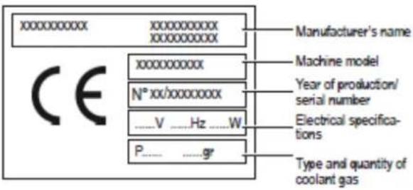
The rating plate on each machine bears the following information:
Translation of the original instructions
Deutsche Version...... Pag.2 - DE
2.3. Dati Tecnici
natural_image
3D rendering of a laboratory instrument with labeled dimensions L, H, and P (no text or symbols on the device itself)2.4. Pannello comandi

5. INSTALLAZIONE

natural_image
3D rendering of a mechanical device with internal components and no visible text or symbols
natural_image
3D mechanical assembly diagram showing a motor and housing component (no text or symbols visible)
natural_image
3D diagram of a kitchen appliance with a pitcher and directional arrows indicating flow or movement (no text or symbols)natural_image
3D diagram of a mechanical device with directional arrows indicating motion or force (no text or symbols)MIN
MAX
- Temperatura del cabinet
natural_image
Cross-sectional diagram of a mechanical device with internal components and a red arrow indicating a specific part (no text or symbols present)
natural_image
Illustration of a hand pressing a mechanical device on a stand (no text or symbols visible)
natural_image
3D rendering of a medical or laboratory device with a red arrow pointing to a circular component, no visible text or symbols.natural_image
3D rendering of a mechanical drill bit with red directional arrow indicating motion (no text or symbols)natural_image
Mechanical assembly diagram showing a valve and bucket with a red upward arrow indicating motion (no text or symbols)natural_image
3D mechanical assembly diagram showing a motor or actuator with red and blue directional arrows indicating motion (no text or symbols present)natural_image
Diagram of a mechanical device with a red curved arrow indicating rotation or force (no text or symbols)natural_image
Mechanical assembly diagram showing a lever and handle with a red arrow indicating motion (no text or symbols)natural_image
Two mechanical components with red arrows indicating rotation or assembly (no text or symbols)natural_image
3D rendering of a metallic cylindrical container with internal mechanical components (no text or symbols visible)natural_image
3D diagram of a spacecraft interior with astronaut suits and directional arrows indicating movement (no text or symbols)natural_image
Three mechanical components with red arrows indicating rotation or assembly, showing different states of change (no text or symbols present)natural_image
Mechanical assembly diagram showing a lever mechanism with a red arrow indicating force or motion (no text or symbols present)
natural_image
Diagram of a kitchen sink with a valve and handle, showing a red downward arrow indicating a component (no text or symbols present)natural_image
Mechanical assembly diagram showing directional arrows (red and blue) indicating movement or force, no text or symbols present.natural_image
3D illustration of a mechanical tool with a red arrow indicating direction (no text or symbols)natural_image
Illustration of a washing machine with red arrows indicating rotation or cycle (no text or symbols)natural_image
Diagram of a mechanical device with blue and red directional arrows indicating motion or force (no text or symbols)natural_image
3D rendering of a mechanical device with a cylindrical component and open door (no visible text or symbols)natural_image
3D rendering of a mechanical device with red and blue directional arrows indicating motion or force (no text or symbols)natural_image
3D diagram of a mechanical device with directional arrows indicating motion or force (no text or symbols)natural_image
Mechanical assembly diagram showing a device with red and blue directional arrows indicating movement or force (no text or symbols present)natural_image
Diagram of a door opening with a blue component and red arrow indicating downward motion (no text or symbols)natural_image
Illustration of a hand reaching toward a control panel with a green indicator light (no text or symbols visible)natural_image
Close-up of a metallic appliance with a red directional arrow indicating flow or movement (no text or symbols)natural_image
3D rendering of a white industrial machine with a red arrow indicating flow or movement (no text or symbols visible)natural_image
Mechanical assembly diagram showing a container with a bag and a lever, no visible text or symbolsnatural_image
3D mechanical assembly diagram showing a motor or pump with red and blue directional arrows indicating motion (no text or symbols present)natural_image
Diagram of a mechanical device with a red arrow indicating rotation or force direction (no text or symbols)SL310011172 Ed 00_IT
natural_image
Mechanical assembly diagram showing a lever and gear mechanism with red directional arrow (no text or symbols)natural_image
Technical illustration of a mechanical assembly with a lever and two views of a component (no text or symbols)natural_image
3D diagram of a kitchen sink with a valve and pipe, showing internal components and a red arrow indicating direction (no text or symbols)natural_image
3D mechanical assembly diagram showing directional arrows (red and blue) indicating movement or force, no readable text or symbols present.2.3. Datos técnicos
natural_image
3D rendering of a laboratory instrument with labeled dimensions L, H, and P (no text or symbols on the device itself)2.4. Panel de mandos

5. INSTALACIÓN

natural_image
Illustration of a hand pouring liquid into a bucket with a stirring rod (no text or symbols)natural_image
Industrial machine with open lid and internal components, no visible text or symbols
natural_image
3D mechanical assembly diagram showing a component with labeled point M (no text or symbols beyond label)
natural_image
3D rendering of a kitchen machine with a pitcher and directional arrows indicating motion (no text or symbols)natural_image
3D diagram of a mechanical device with directional arrows indicating motion or force (no text or symbols)natural_image
Three identical grid diagrams with green horizontal lines inside, no text or symbols presentMIN
MAX
natural_image
Cross-sectional diagram of a mechanical device with internal components and a red arrow indicating a specific part (no text or symbols present)
natural_image
Illustration of a hand pressing a button on a mechanical device (no text or symbols visible)
natural_image
3D rendering of a medical CT scanner with a red arrow pointing to the dial (no text or symbols visible)natural_image
3D rendering of a mechanical tool with a red arrow indicating direction (no text or symbols)natural_image
Mechanical assembly diagram showing a valve, pipe, and component with a red arrow indicating direction (no text or symbols)natural_image
3D mechanical assembly diagram showing a motor with red and blue directional arrows indicating motion (no text or symbols)natural_image
Simple line drawing of a mechanical device with a red curved arrow indicating rotation (no text or symbols)natural_image
Mechanical assembly diagram showing a lever and clamping mechanism with red arrows indicating motion (no text or symbols)natural_image
Two mechanical components with red arrows indicating rotation or assembly motion (no text or symbols)natural_image
Illustration of a mechanical component inside a cylindrical container (no text or symbols visible)natural_image
Illustration of a hand reaching toward a medical device with a monitor and control buttons (no text or symbols)natural_image
3D diagram of a medical device interior with red arrows indicating movement or force, no visible text or symbolsnatural_image
Four-step assembly diagram showing a device with red arrows indicating rotation or adjustment (no text or symbols)natural_image
Mechanical assembly diagram showing a lever mechanism with a red arrow indicating force or motion, alongside a close-up of a mechanical component (no text or symbols present)
natural_image
Interior view of a kitchen sink with a valve and pipe, showing a red downward arrow indicating a component (no text or symbols present)natural_image
Mechanical assembly diagram showing directional arrows (red and blue) indicating movement or force, no text or symbols present.natural_image
3D illustration of a mechanical tool with a red arrow indicating direction (no text or symbols)natural_image
Illustration of a washing machine with red arrows indicating clockwise motion (no text or symbols)natural_image
3D diagram of a mechanical device with blue and red directional arrows indicating motion or flow (no text or symbols)natural_image
Illustration of a chemical reactor with open chamber and internal components (no text or symbols visible)natural_image
3D rendering of a kitchen machine with a mug and directional arrows indicating motion (no text or symbols)natural_image
3D diagram of a mechanical device with directional arrows indicating motion or flow (no text or symbols)natural_image
Mechanical device with red and blue directional arrows indicating movement or force (no text or symbols)natural_image
Diagram of a door opening with a blue component and red arrow indicating direction (no text or symbols)natural_image
Illustration of a hand reaching toward a control panel with a green display (no text or symbols visible)natural_image
Close-up of a metallic bowl with a red arrow pointing to it, no visible text or symbolsnatural_image
Illustration of a laboratory instrument with a red arrow indicating direction (no text or symbols present)natural_image
3D diagram of a kitchen sink with a bag, pipe, and valve (no text or symbols)natural_image
3D mechanical assembly diagram showing a motor or pump mechanism with red and blue directional arrows indicating motion (no text or symbols present)natural_image
Diagram of a mechanical device with a red curved arrow indicating rotation or motion (no text or symbols)natural_image
Mechanical assembly diagram showing a lever mechanism with a red arrow indicating motion (no text or symbols present)natural_image
Technical illustration of a mechanical assembly with a lever and two views of a component (no text or symbols)natural_image
Diagram of a kitchen sink with a valve and pipe, showing a red downward arrow indicating a component (no text or symbols present)natural_image
3D mechanical assembly diagram showing directional arrows (red and blue) indicating movement or force, no text or symbols present.3.1. General safety guidelines
3.2. Stop functions
3.3. Plates
4. MOVING AND STORAGE
4.1. Packing
4.2. Transport and movement
4.3. Storage
5. INSTALLATION
5.1. List of included accessories
5.2. Assembly-Placement
5.3. Package disposal
5.4. Electrical connection
6. OPERATION
6.1 Product preparation
6.2. Machine start-up
6.2.1 Product loading
6.2.2 Ice-cream production start-up
6.2.3 Maintenance start-up
6.3. Ice-cream consistency regulation
6.4. Ice-cream output
6.5. Deals counting
6.6. Making of a fridge manual defrost
6.7 Messages that may appear in the display while operating
6.8. Emergency situations
7. CLEANING AND MAINTENANCE PROCEDURES
7.1 Cleaning and sanitizing
7.1.1 Emptying the machine
7.1.2 Tap body disassembly
7.1.3 Agitator disassembliy
7.1.4 Disassembly of product suction tube
7.1.5 Cleaning and sanitizing of components
7.1.6 Cleaning and sanitizing of cylinder
7.1.7 Assembly of product suction tube
7.1.8 Agitatorrer assembly
7.1.9 Tap body assembly
7.1.10 Final cycle of sanitizing and rinse of the
machine
7.2 Cleaning of fridge
7.3 Cleaning of external drip tray
7.4 Cleaning of air filters
7.5 Replacement of the product suction pump tube
7.6 Periodic maintenance
8. DISPOSAL
9. PROBLEMS – CAUSES - SOLUTIONS
10. ALARMS
1. GENERAL INFORMATION
1.1. Manufacturer
Information regarding the manufacturer can be found on the first and/or last page of this manual.
1.2. Employees
Two employees with different roles can have access to the machine.
Operator
A person with suitable technical knowledge regarding the preparation of products used by the machine according to the applicable hygiene standards.
Who having read this manual is able to:
- Perform the usual operations for loading and/or replacement of consumer products.
- Correctly prepare the product.
- Suitably clean and sanitize the machine.
This device can be used by children aged 8 years and above and persons with reduced physical, sensory or mental capabilities or with lack of experience and knowledge if they are supervised or trained appropriately regarding the use of the machine safely and understand the risks. The cleaning and maintenance must be performed by the operator, should not do it unsupervised children.
Specialized technician
A person who after reading this manual is specialized in the installation, use and maintenance of the machine:
- In the case of grave operational faults is capable of carrying out repair, is familiar with the contents of this manual and all relevant Safety information.
- Is capable of understanding the contents of this Manual and can correctly interpret Diagrams and Plans.
- Is familiar with the basic rules of hygiene, accident prevention, technology and safety
- Has specific experience in ice-cream machine maintenance.
- Knows how to act in the case of emergency, where to find individual means of protection, and how to use them properly.

It is forbidden to allow people who do not meet the above requirements to use the machine.
1.3. Manual layout
The information contained in this Manual must be read carefully by the Customer.
1.3.1. Objective and contents
This Manual provides the Customer with all of the necessary information for the machine's installation, maintenance and use.

Before carrying out any type of operation on the machine, the operators and specialized technicians must carefully read the instructions described in this document.
In the case of any queries in relation to the correct interpretation of these instructions, please contact the manufacturer for clarification.

The performance of any operation is forbidden, without first having read and fully understood the contents of this manual.
1.3.2. Recipients
This manual has been created for operators and specialized technicians.
The operators must never carry out operations which are reserved for specialized technicians.
The manufacturer is not liable for damages resulting from breach of this prohibition. The instruction manual forms part of the acquired product and must accompany it at all times, also in the case of delivery to new owners of the product.
1.3.3. Conservation
The instruction manual must be kept in close proximity to the machine. To guarantee the integrity and timely consultation of this manual it is advisable to follow these instructions:
- Handle the manual with care so as not to damage it partially or entirely.
- Under no circumstances should parts of the manual be torn, removed or written on.
- It should be stored in areas free from humidity and heat so that the quality of the publication is preserved and it is totally legible.

In the case of loss or serious deterioration of this manual, you should immediately request another copy from the manufacturer or authorized distributor in the machine's country of use.
1.3.4. Symbols used
GENERAL DANGER

Indicates danger that involves risks, including mortal risk for the user. Maximum attention must be paid to this case and all necessary means must be taken for safe operation.
ELECTRIC SHOCK HAZARD
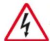
Notify the person involved about the risk presented by the operation and that there is a risk of electric shock, if the applicable safety standards are not followed.
WARNING

This indicates a warning or notice about key functions or useful information. Very close attention should be paid to blocks of text that appear with this symbol.
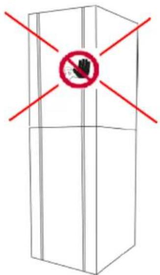
FORBIDDEN

The presence of this symbol indicates operations whose execution should be totally avoided, given that they involve danger to the user and other persons, who operate in the vicinity of the machine.
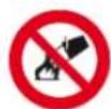
FORBIDDEN TO PUT OUT FIRE WITH WATER

This sign indicates that it is forbidden to put out fires with water or with any other substance containing water.
PERSONAL PROTECTION

The presence of this symbol beside the description indicates that the operator should use personal protection as there is a risk of accident.
SPECIALIZED TECHNICIAN

Highlights the interventions that can only be made by specialized technicians.
MOVING BODIES

Indicates danger due to the presence of moving bodies in the machine. Turn off the machine before carrying out any operation.
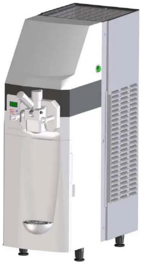
2. Machine description
2.1. Machine use
The machine for professional use that you are utilising is ideal for the production of creamy ice-creams also known as "soft".
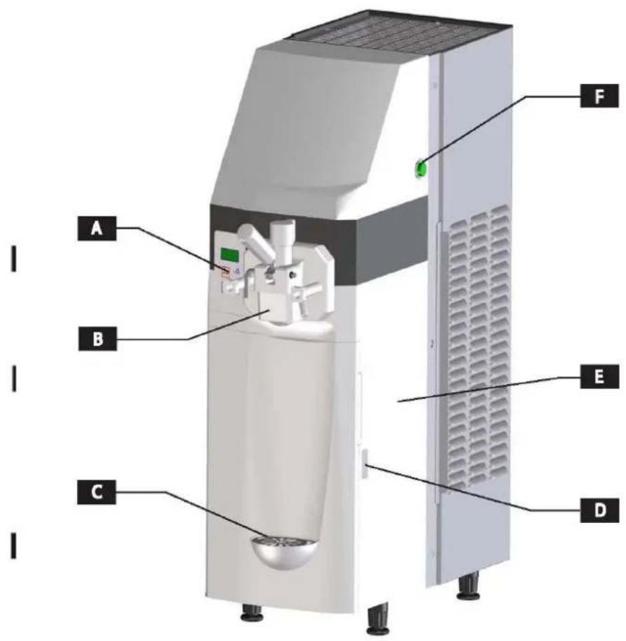
2.2. Main components
A. Control panel
B. Tap body
C. Drip tray
D. Fridge door enclosure lever
E. Fridge
F. Main switch
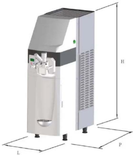
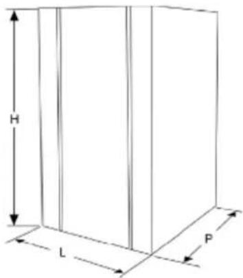
2.3. Technical details
The table shows the data and specifications.
| Model | 141 |
| DimensionsL x P x H (mm) | 290 x 580 x 870 |
| Machine weight (kg) | 88 |
| Maximum power consumed(W) | See the technical detailplate located on theback of the machine |
| Operating voltage (V) | |
| Operating temperature | Min. 25°C - Max 32°C |
| Flavours | 1 |
| Fridge tank capacity | 5 L |
| Hourly production* | 180 portions of 70 g |
| Recommended portion | 70 g |
| Probe pressure | <70 dBA |
| Class | N |
* The production and the quantity of the mixture can vary depending on the temperature and the type of mixture used. The performances refer to a 25°C room temperature.

Note: The manufacturer reserves the right to make modifications to the machine without giving prior notice.

Warning! Any modification and/or addition of accessories must be explicitly approved and performed by the manufacturer.
natural_image
3D rendering of a laboratory instrument with labeled dimensions L, H, and P (no text or symbols on the device itself)2.4. Control panel
The controls and the symbols of the control panel are described as follows:
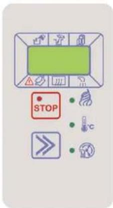
| Mode: STOP | Viewed on display: StP |  |
During this mode the machine is stopped and the associated red LED lights up. The display shows StP.
| Mode:Selection | Viewed on display:Prd, Sto,CLE |  |
By pressing this key several times the following modes can be selected: Prd (ice-cream production), Sto (maintenance), CLE (clean/load/empty).
The key also serves to eliminate any alarms/messages that may appear on the screen.
STORE mode (Sto)
The lighting LED indicates that the mode is activated

CLEAN/LOAD/EMPTY mode (CLE)
The lighting LED indicates that the mode is activated

PRODUCTION mode (Prd)
The lighting LED indicates that the mode is activated

Tank product REFILL need ICON

Tank product STIR need ICON
Machine WASH requirement ICON
3. Safety

3.1. General safety guidelines
- Read the entire instruction manual carefully.
- The connection to the electrical power supply must be done according to the safety standards of the country of use.
- The power supply where the machine will be connected, must:
- Conform with the type of plug installed on the machine.
- Have dimensions as described on the data plate located on the machine.
- Be connected to an efficient earthing.
- Be connected to a differential circuit breaker installation.
• The power supply cable should not:
- Come into contact with any kind of liquid: risk of electric shock and/or fire.
- Be squashed or come into contact with sharp edges.
- Be used to move the machine.
- Be used if damaged.
- Be handled with wet or damp hands.
- Be rolled up while the machine is in operation.
- Be manipulated.
- It is forbidden to:
- Install the machine in ways that are different to those illustrated in Ch. 5.
- Install the machine in areas exposed to jets of water.
- Use the machine near flammable and/or explosive substances.
- Leave plastic bags, polystyrene, nails etc., at the reach of children, as they are potential sources of danger.
- Let children play or be in the vicinity of the machine.
- Use replacements that are not approved by the manufacturer.
- Introduce any kind of technical modification to the machine.
- Submerge the machine in any kind of liquid.
- Wash the machine using jets of water.
- Use the machine for any means other than those described in the manual.
-
Use the machine while under the influence of drugs, alcohol, psychoactive drugs, etc.
-
Install the machine on top of other apparatuses.
- To use the machine in potentially explosive or corrosive environments or with a high concentration of dust or oily substances suspended in the air.
- To use the machine in environments subject to fire risk.
- To use the machine to elaborate substances that are not suitable for the machines characteristics.
- Do not wash the machine using gasoline or any kind of solvents.
- Repairs should be performed solely by a Support Centre which has been authorized by the Manufacturer and always by specialized and trained personnel.
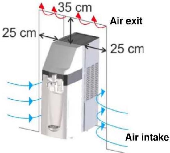
- Do not obstruct the vents situated on the sides of the machine.
- Do not place the machine near heating systems (such as a heater or radiator).
- In the case of fire use carbon dioxide (CO2) extinguishers. Do not use water or powder extinguishers.

In case of improper use all guarantees becomes invalid and the manufacturer accepts no liability for material and/or personal damage.
The following is considered as improper use:
- Any use and/or technical application different to those which are illustrated in this manual.
- Any machine intervention that contradicts the instructions of this manual.
- Any use after the manipulation of components and/or alteration of safety devices.
- Any use after repairs made with components not authorized by the manufacturer.
- The outdoor installation of the apparatus.
3.2. Stop functions
The machine's stop functions are controlled by the main switch located on the right hand side of the machine which cuts off the power supply to the machine entirely.
3.3. Plates
NONE OF THE PLATES PRESENT ON THE MACHINE SHOULD BE REMOVED, COVERED OR DAMAGED, ESPECIALLY THOSE WHICH ARE USED FOR SAFETY.
4. MOVING AND STORAGE
All operations described in Chapter 4 are to be exclusively performed by specialized technicians, including the elevation and movement operations for packaged and non-packaged machines. These operational sequences must be planned depending on the characteristics and weight of the object to be moved, using suitable means which respect the regulations applicable for the material in question.

4.1. Packing
The machine is sent ready for use, packed in a cardboard box. This cardboard box is made up of a base and a cover, held in place with two strips of nylon.
PAKING DIMENSION AND WEIGHT
| Length (L) mm | Profundity (P) mm | Height (H) mm | Weight kg | |
| 121c | 390 | 775 | 1050 | 98 |

Note: the dimensions and weight of the packaging are representative values.
4.2. Transport and movement

Ensure that there is no-one in the range of the lifting and moving of the load and in difficult circumstances the movement should be supervised by competent personnel.
The manual movement of the machine should be done by at least two persons.
The machine should be moved in an upright position.
Lift the package and transport it with care, avoiding accidental movements and paying attention to its dimension and possible out jutting objects.
Any produce inside the machine must be removed before it is moved.

It is forbidden to perform additional cuts on the packaging.
Damages caused to the machine during transport and movement are not covered by the GUARANTEE. Repair or replacement of damaged parts is the sole responsibility of the Customer.
4.3. Storage

Before storing the machine and before using a machine that has been stored for a long period of time, it must be well cleaned and sanitized.
Warning: do not pile the machines during storage.
In the case of long periods of inactivity the machine must be stored with precaution regarding the place and the storage time:
- Store the machine in an enclosed area.
- Protect the machine against shocks and stresses.
- Protect the machine against dampness and large oscillations in temperature.
- Avoid contact of the machine with corrosive substances.
5. INSTALLATION

All operations described in Chapter 4 are to be exclusively performed by specialized technicians. These operational sequences must be planned using suitable means which respect the regulations applicable for the material in question.
This machine is a counter-mounted dispensing freezers. The machine must be installed inside a building with lighting, air, and a solid stable and level floor (inclination lower than 2^2 ).

The apparatus must be monitored and should be installed in places where it can be observed by trained personnel.

Warning: it is forbidden to install the machine in places where it can be reached, touched and/or turned on by persons other than those specified in section 1.2.
The machine must operate in environments with a temperature between 25 and 32 °C.
5.1. List of included accessories
The following material is delivered with the machine:
- n°1, product suction pump kit
- n°3, Air flow regulator
- n°1, O-rings kit
- n°1, Nylon brush
- n°1, Soft-Shake carpilube tube
- n°1, O-ring joint extractor
5.2. Assembly-Placement
The operator must check the following:
- That the place is prepared for the machine's installation.
- That the surface for the machine's installation is hard, flat and firm.
- That the area has sufficient lighting, ventilation and hygiene, with easy access to the power supply.
The machine's access areas must remain clear to:

- Enable air circulation.
- Enable the operator to intervene without obstruction.
- Enable the quick evacuation of the work area if necessary.
The minimum required spaces are described as follows.
After having placed the package near the installation area proceed as follows:
- Cut the strips that hold the packaging in place.
- Lift the cardboard packaging.
- Then place the machine in the prepared area.

Before starting the machine for the first time, its components must be cleaned and parts that come into contact with the product must be sanitized; for further information please consult the corresponding section.
5.3. Package disposal
Once the packaging is opened it is advisable to separate it into types of material and to dispose of it according to the applicable regulations in the country of use. It is advisable to keep the packaging for later movements or transport.
5.4. Electrical connection
This operation should only be performed by specialized technical personnel.
The customer is solely responsible for the machine's electrical connection.
The machine should be connected to the electrical network using the plug that is on its electrical cable, considering:
• The applicable laws and regulations at the time of the installation.
- The data indicated on the technical detail plate which is fixed to the side of the machine.

Warning: the connection point to the power supply must be of easy access to the user, to ensure that the machine can be easily disconnected from the power supply if necessary.
If the power supply cable is damaged only contact the manufacturer or a specialized technician for its replacement.

It is forbidden to:
- Use any kind of extension lead.
- Replace the original plug.
- Use adaptors.
The machine connection to the electric power distribution must be permanent if laws and local regulations require it. Contact a specialized technician to remove the supply cable provided with the machine and to connect the machine to the electric power distribution as indicated by the laws and local regulations.

6. OPERATION
Before turning on the machine for the first time, its proper installation must be verified by a specialized technician.

Close the pump cover before the first use of the machine
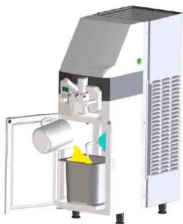
6.1 Product preparation
Prepare the product in a container according to the manufacturer's instructions.
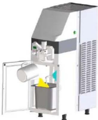
Pour the product into the tank which is located inside of the fridge. Add a maximum of 5 L of produce. Once the product has been poured into the tank, close it using the corresponding lid.
natural_image
3D rendering of a white industrial machine with open door and internal components (no visible text or symbols)
The fridges only function is to maintain the products temperature and not to reduce it. DO NOT ADD HOT LIQUIDS. ONLY ADD LIQUIDS WITH A TEMPERATURE OF 3-4 °C.

The machine does not preserve the products for an indefinite amount of time. The products added to the machine must be consumed within a period defined by their manufacturer.

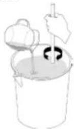
The machine does not move the product stored in the tank within the fridge. It is advisable to agitate the produce manually if the machine is not used continuously throughout the day.
6.2. Machine start-up
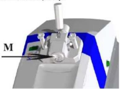
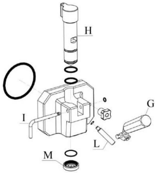
Before starting the machine check that the M part is properly assembled at tap body.
natural_image
3D rendered mechanical device with labeled component 'M' (no readable text or symbols beyond label)
It is not allowed to use the machine in absence of the M component correctly assembled on the tap body The M component must only be removed from the machine in STOP mode and with the general switch off.
6.2.1 Product loading
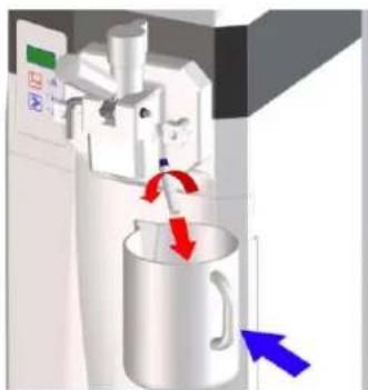
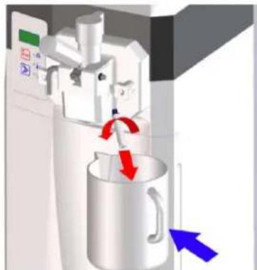
- Remove the tap body bolt.
- Ensure that the tap dispensing lever is closed.
- Place a container under the tap body bolt hole.
natural_image
3D diagram of a kitchen machine with a pitcher and directional arrows indicating motion (no text or symbols)- Start the clean/load/empty function. Press the selection key several times until the CLE message appears on the display. The green LED beside the clean/load/empty symbol lights up. The machine begins to load the product into the churning cylinder.
| Mode: CLEAN/LOAD/EMPTY | Viewed on display: CLE |
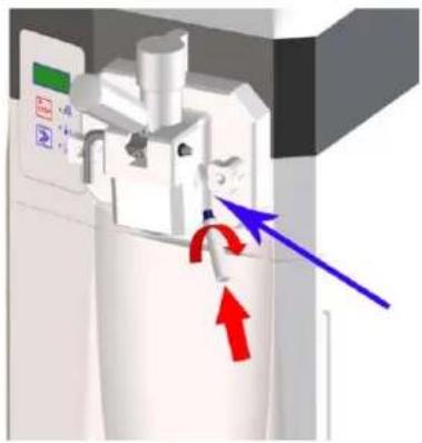
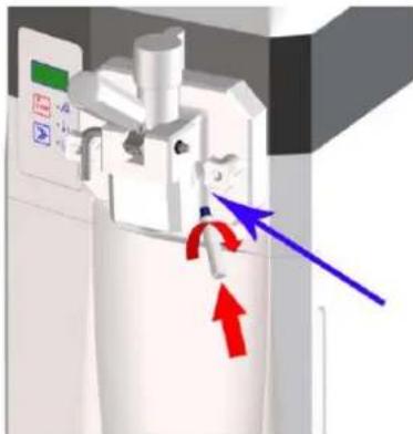
- When a constant flow of product through the tap body hole bolt is observed, press stop key STOP. -Close the tap body bolt hole by replacing the bolt. -Clean the product that may remain.
natural_image
3D diagram of a mechanical device with directional arrows indicating motion or force (no text or symbols)6.2.2 Ice-cream production start-up
Once the product has been loaded the machine is in STOP mode. To activate the ice-cream production function press the selection key ▶ until the Prd message appears on the display. The green LED beside the Production symbol lights up. The machine begins to produce ice-cream. In a few minutes the ice-cream will reach its configured consistency.
| Mode: PRODUCTION | Viewed on display: Prd |
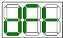
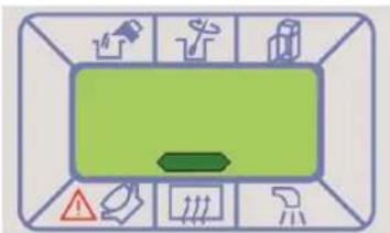
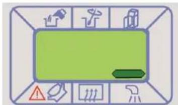
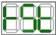
During the production function the display shows the following:
- NO
The product does not have the right consistency.
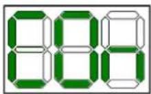
- Ice-cream production in process
The process of ice-cream production is represented by the progressive illumination of the display which shows the progressive increase in product consistency.
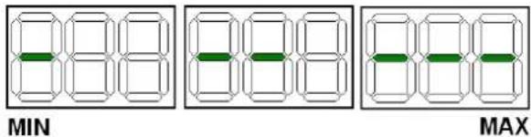
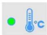
- Fridge temperature
In real time, it shows the internal environmental temperature of the refrigeration fridge and shows that the ice-cream is ready.
6.2.3 Maintenance start-up
During the closing periods of your establishment it is possible to set the machine to maintenance mode. In this manner it will save a considerable amount of electricity given that the compressor will only operate for the time necessary to preserve a suitable product temperature (max. 4 °C). When the establishment is re-opened the machine can be placed in production mode and in a few seconds the ice-cream will reach the required consistency to be sold again. To set the machine to maintenance mode proceed as follows:
- Stop the machine by pressing STOP STOP -Press the selection key ▶ until the Sto message appears on the display. The green LED beside the maintenance symbol lights up and maintenance mode begins.
| Mode: Maintenance | Viewed on display: Sto | 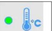 |
During the maintenance the display shows the fridge temperature, to watch the temperature of the product in the cylinder, press the selection key. The display will show this temperature during 5 seconds

If the machine stops due to interrupted electrical power supply, before starting to sell again, it is essential to check the temperature of the produce; if the temperature has exceeded +6 °C then the machine must be emptied, clean and sanitized, and then refilled with new fresh produce at +4 °C. The maintenance start-up cannot be used to do the cleaning and the sanitizing of the machine.
6.3. Ice-cream consistency regulation
The product consistency can be changed as follows:
- Stop the machine by pressing STOP STOP
- With the machine at STOP, simultaneously press the keys
stop STOP and selection >> and release them when the display shows the message HOT (consistency) and its value. - Now by means of the selection key ➕ the product consistency can be modified (min. 40 – max. 120). Increasing this number increases the hardness of the ice-cream.
- Wait 30 seconds to memorize the value and the machine will automatically return to Stop.
6.4. Ice-cream output
To serve the product all that is required is to place a tub or a cone underneath the ice-cream tap and slowly lower the lever. Once the product begins to come out, stop lowering the lever and move the tub or cone in a circular motion to serve the ice-cream in a cone shape. Once a sufficient amount of produce has been served, raise the lever and move the tub or cone downwards to give the end of the portion that point shape. Distribute the ice-cream without exceeding the machine's production rhythm as indicated in section 2.3. Not exceeding this rhythm and remember to restock the machine with fresh can guarantee uninterrupted sales even during rush hours.
6.5.Deals counting
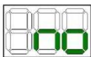
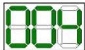
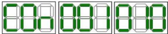
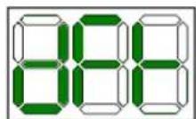
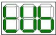
This machine has a total deals counter since its first start up. Proceed as follows in order to watch the total number of deals served:
-switch on the machine
- the display will show the message Con
a number is shown immediately indicating the thousands followed by another number that indicates the deal units
Example: The following numbers series shows that it have been made 1010 deals until the moment.
6.6. Making of a fridge manual defrost
To activate the manual defrost function proceed as follows: -Select the production function
-In order to make a manual defrost push the selection key when the display shows the fridge temperature and wait for the message dFr. This message will appear during the whole defrost time. In case of have activated this function by mistake, push the selection key once again to stop it.
- Once the operation has finished push the Stop key - Remove with a dry cloth the drops of water that could remain in the fridge evaporator and restart the machine.
If the ice persists repit the operation until its complete disappearance.
6.7 Messages/symbols that may appear in the display while the operation
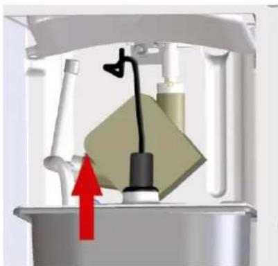
- Tank refill requirement
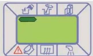
In PRODUCTION (Prd) mode, when this signal appears on the display, the machine enters CONSERVATION (Sto)

mode and the product's supply is blocked.

Always fill the tank when requested. The pump must not work empty and/or without product.
After filling the tank, the signal on the screen will disappear and you can return the machine to frozen PRODUCTION (Prd)

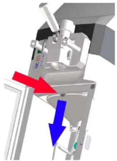
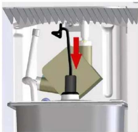
The mixture level is detected by sensors in the tank; therefore, when filled, you must check that the connector is properly connected to the level sensors.
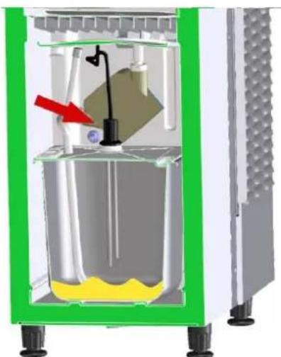
natural_image
Cross-sectional diagram of a mechanical device with internal components and a red arrow indicating a specific part (no text or symbols present)
The machine makes a noise while a sign is simultaneously displayed on the screen.
This message indicates that the fridge door is open. The message desappears by closing the door.
-dFr
The automatic defrost function is activated.
- Fridge defrost requirement
The message above appears at the dispay when the fridge is investing too much time in reaching the operation temperature. The reason may be an excessive ice accumulation on the evaporator surface. In this case a manual defrost is advised (see chap 6.6)
Press the selection key ➤ in order to remove the message from the display.
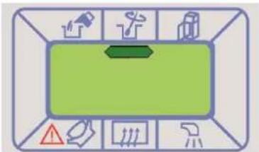
- Wash request message
This message means the need to clean the machine. If the massage appears in the display while the production function, it doesn't stop and it is possible to ignore the message by pressing the selection key ▶. If the machine is in stop and the wash message is shown it will not be possible to activate the production nor maintenance functions. It only will be possible to activate the clean function. To restart the operation mode it is necessary to clean the machine (see cap. 7)
The following procedure shows how to disable this function or how to change the number of days reached to show the message at the display.
- Select STOP mode
- Push at once STOP STOP and SELECTION >> keys until HOT message is shown at the display.
- Push STOP more times until the wash message is shown
- By means of SELECTION key set 0 to disable the function or select the number of days desired after which the message will appear at the display.
- The machine will go back in STOP mode STOP automatically.


The machine cleaning and sanitization must be made necessarily 72 hours after the introduction of the product.
- Tub
This message means the need to change the persitaltic pump tube (see cap. 7.5)
To cancell the tUb message proceed as follows:
- Stop the machine by pressing the key STOP STOP, and keep pressing until the rSt message appears in the display

If the pump tube has been changed before the tUb message appears in the display it is necessary to act as if it had appeared to communicate the machine that the tube has been changed.
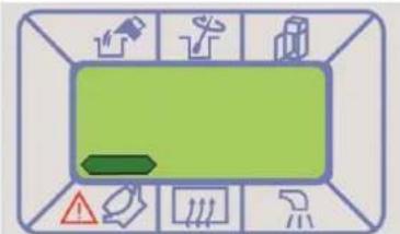
- Tank product stir request
The machine warns periodically stirring the product in the tank. When the message above is shown at the display proceed to stir the tank product manually in order to keep it smooth. The message will disappear automatically from the display by opening the fridge door.
The following procedure shows how to disable this function:
- Select STOP mode
- Push at once STOP STOP and SELECTION >> keys until HOT message is shown at the display.
- Push STOP more times until the message above disappears.
- By means of SELECTION key ▶ set YES to active this function or NO to disable it.
- The machine will go back in STOP mode STOP automatically.

- Wrong cylinder mix loading message
The message above indicates an error in the cylinder loading, which can be caused by one of the following causes. It is necessary check all of them and act adequately.
1) Fridge tank empty. Refill the tank with product and load the cylinder. (See chap. 6.2.1)
2) Tank product too dense. Change the air flow regulator with the other one supplied with the machine which is marked with a lower number. If the problem persists or the product consistency is not the desired maybe the product is not suitable to be used in this machine. Use a less dens product.
3) Uncorrect assembly of the suction pipe. Check that the suction pipe has been well assembled as indicated in chap. 7.1.7.
4) Load circuit product loss. Check if there is a product loss in the load circuit caused by a pipe/joint break. In this case change the broken pipe/joint with one of the supplied with the machine.
5) Air flow regulator uncorrectly assembled. In this case make a correct assembly as is shown at chap. 7.1.7.
6) Air flow regulator unsuitable that involves a higher air proportion than right one. Choose the appropriate air flow regulator size.
Push the selection key ➕ in order to remove the message from the display.
6.8. Emergency situations

WARNING: in the case of emergency the machine can be stopped by pressing the
STOP STOP button and unplugging it from the power supply.
In the case of the machine becoming blocked due to freezing, turn off the machine and contact the support centre or a specialized technician.
In the case of fire, the area must be evacuated immediately to allow for the intervention of trained personnel who are equipped with the suitable means of protection. Always use approved fire extinguishers and never use water or unknown substances.
7. CLEANING AND MAINTENANCE PROCEDURES

Before performing any operation related to machine maintenance or cleaning, it is essential to use the personal protective equipment (gloves, glasses, etc...) set by the safety regulations in force in the country of use.
When performing Cleaning and Maintenance tasks, please do so as follows:
- Use protective latex gloves to avoid accidents. Then wash the hands with a sanitizing solution.
- Do not use solvents or flammable material.
- Do not use metallic and/or abrasive sponges to wash the machine or its components.
- Try not to disperse liquids into the environment.
- Do not wash the machine's components in the dishwasher.
- Do not use a conventional oven or a microwave to dry machine parts.
- Do not submerge the machine in water.
- Do not spray the machine directly with jets of water.
- For cleaning purposes use tepid water, a degreasing detergent and a suitable sanitizer detergent according to 21CFR1781010 (in any case set by the safety regulations in force in the country of use, ex: kay-5 sanitizer) which does not damage machine components.
- When the job is done, correctly replace and reassemble the removed or opened casings and protections.
Cleaning and sanitizing operations must be done regularly and with great care to guarantee quality and production and respecting the applicable hygiene standards.
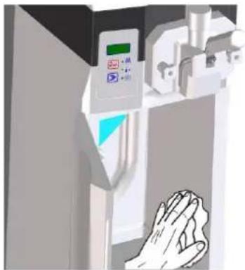
The machine's cleaning and sanitization should be performed at least once a day always respecting the applicable standards for hygiene in the country of use. If required by the products characteristics these operations should be performed more frequently; for further information please consults the product's manufacturer. In the case of the machine not being used continuously throughout the day, the product's tap and output pipe must be cleaned using a clean cloth dampened with a detergent solution as shown on the following figure

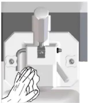
natural_image
Illustration of a hand washing a small mechanical device (no text or symbols visible)
The stainless steel, plastic and rubber used to make these parts aid their cleaning but do not prevent the formation of bacteria and mould in the case of insufficient cleaning.

The ice-cream contains fats which are ideal breeding grounds for fungus and bacteria. In order to remove them the bodies that come into contact with the product must be washed and cleaned with great care.
The ideal temperature of the water for washing and sanitizing should not exceed 40°C.
7.1 Cleaning and sanitizing
The cleaning and sanitizing procedure of the machine consists of:
- Emptying the machine
- The tap body disassembly
- The agitator disassembly
- The suction tube disassembly
- Cleaning and sanitizing of all the components
- Cleaning and sanitizing of the cylinder
- Assembly of all the washed components
- Sanitizing and final rinse of the machine
7.1.1 Emptying the machine
To empty the contents of the machine, proceed as follows:- -
Press the stop button STOP to stop the machine
- Remove the product tank from the fridge
- Place a container under the body tap.
- Open the ice-cream output tap by lowering the lever
- Start the clean/load/empty function. Press the selection key
until the CLE message appears on the display. The LED beside the clean/load/empty symbol lights up and the machine starts the function. Press the selection key again to start the agitator.
| Mode:CLEAN/LOAD/EMPTY | Viewed ondisplay:CLE |
- Holding the container underneath the tap, let the ice-cream come out of the churning cylinder and wait until the machine stops automatically.
- Close the tap by raising the tap lever.
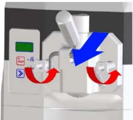
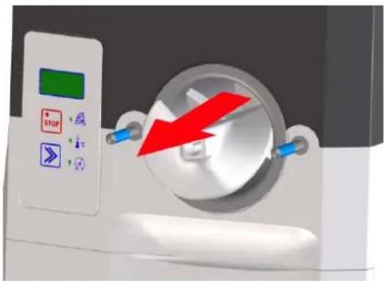
7.1.2 Tap body disassembly

Before disassembling the tap body make sure that the machine is in STOP as inside the cylinder there are moving bodies that may cause injury
Keep a container in place under the churn tap body given that product residue can come out of the churning cylinder during the operation.
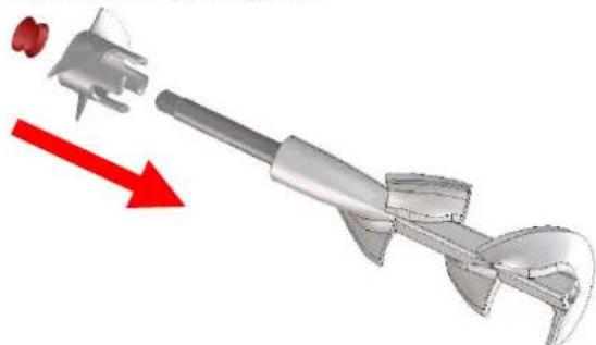
To dismantle the machine's tap body, slowly loosen and remove the handles. Remove the tap body by puling it towards the outside of the machine..
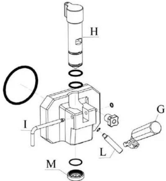
Remove any possible product residue from the tap body and dismantle it as follows:
- using the lever (G), raise the plunger (H).
- remove the O-ring and the tap pin (I) that block the lever (G).
- remove the lever (G).
- remove the plunger from its place (H).
- remove the tap body bolt (L).
- remove the reduction-to-star (M) from its place.
- remove the rest of O-rings.
7.1.3 Agitator disassembly
Remove the agitator from its place inside the cylinder, taking special care not to hit off the cylinder wall.
natural_image
Medical CT scan device with red arrow indicating compression or compression (no text or symbols)Remove the drive shaft seal and the blade extension by sliding along the length of the shaft.
natural_image
3D mechanical component with red directional arrow indicating movement or force (no text or symbols)7.1.4 Disassembly of product suction tube
To remove the product suction tube, proceed as follows:
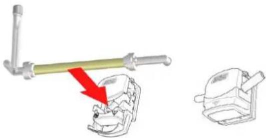
- Disconnect the level sensor connector by pulling upwards and remove the tank

natural_image
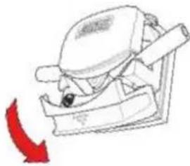
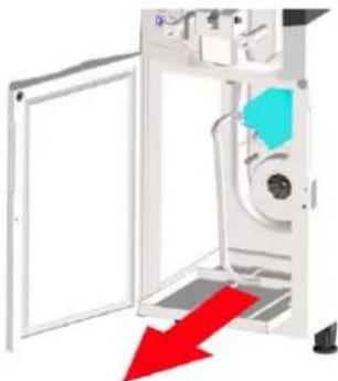
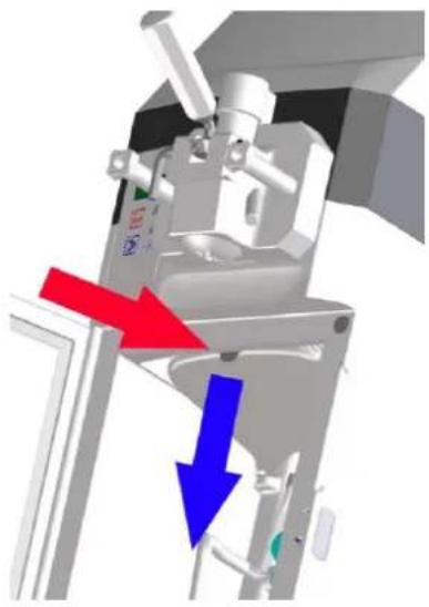
Mechanical device with a yellow component and red arrow indicating upward motion (no text or symbols)- Remove the fridge top tray from inside the fridge. Press the tray retainer and remove it pulling downwards.
natural_image
3D mechanical assembly diagram showing a motor or actuator with red and blue directional arrows indicating motion (no text or symbols present)SL310011172 Ed 00_EN
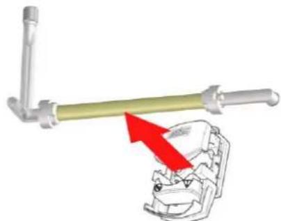
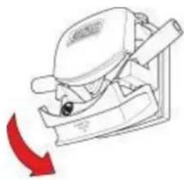
- Open the peristaltic pump by opening its lid.
natural_image
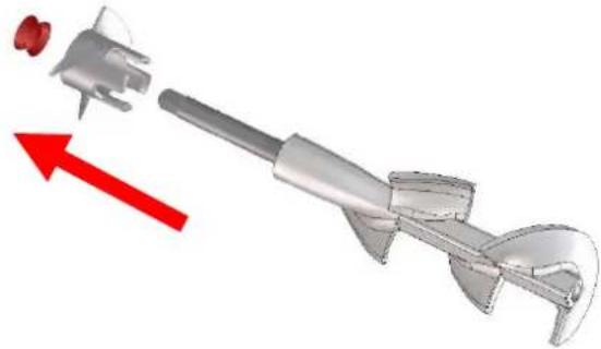
Line drawing of a mechanical device with a red arrow indicating direction (no text or symbols)Extract the product suction tube by carefully removing it from the peristaltic pump.
natural_image
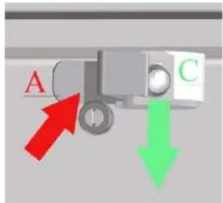
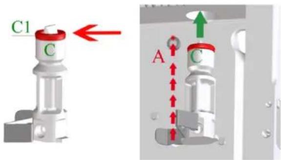
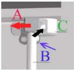
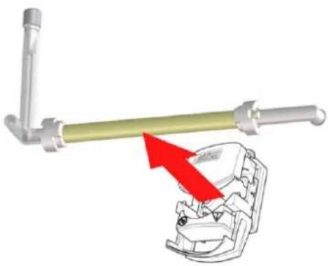
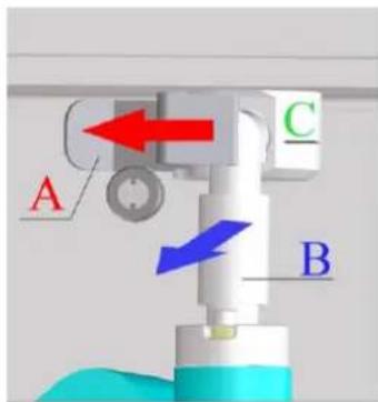
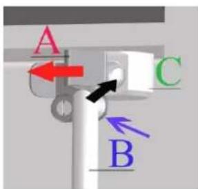
Mechanical assembly diagram showing a lever and clamping mechanism with red arrows indicating motion (no text or symbols)- Pull the inlet pipe subjection (A) to the left and extract the connection joint (B) from the inlet pipe (C).
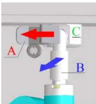
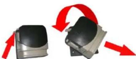
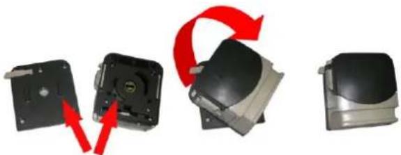
- To remove the pump body press its subjection placed on its left and keeping it pressed turn the pump anticlockwise until unblock it. Extract the pump then, pulling it.
natural_image
Two mechanical components with red arrows indicating rotational motion (no text or symbols)-unblock the inlet pipe subjection (A) and remove the inlet pipe (C) by pulling it downwards.
- Remove the joint (C1) and the non-return valve (D) from the inlet pipe (C)
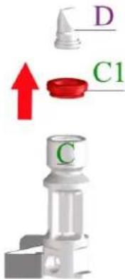
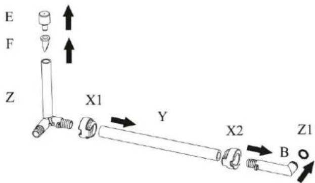
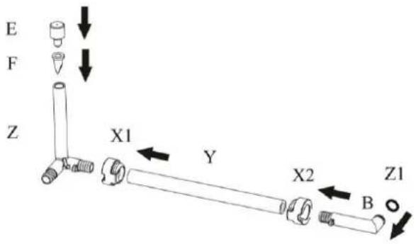
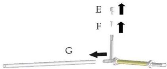
- Extract the air flow regulator (E) and the air inlet valve (F) from the joint of the pump suction tube (Z) by pulling up; then remove the bushings (X1) and (X2), the tube (Y) and the joint (B) pulling horizontally. Finally remove the O-Ring of the joint B from its seat.
7.1.5 Cleaning and sanitizing of components
To clean and sanitize the dismantled parts proceed as follows:
- Wash all disassembled components including the product tank with drinkable water and detergent, by using the nylon brush supplied with the machine in order to clean even in the internal side of the tubes.
- Rinse with clean water all components, making sure to remove all traces of grease/product from all surfaces.
- Fill a bucket with disinfectant solution and introduce all of the previously disassembled components.
- Let the solution work for 10/15 min.
- Rinse the elements thoroughly using drinking water.
- Place the components on a dry tray and let them drip dry.
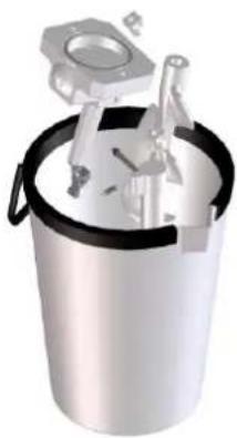
natural_image
3D rendering of a metallic bucket containing mechanical components (no text or symbols visible)7.1.6 Cleaning and sanitizing of cylinder
While the disassembled components are soaking in the disinfectant solution, clean and sanitize the churning cylinder as follows:
- Remove any product residue from the churning cylinder. - Wash the cylinder using a not abrasive sponge soaked with drinking water and detergent.
- With the supplied brush soaked in detergent water clean the hole between the fridge and the cylinder and the cylinder product loss groove.
-Rinse with clean water the hole between the fridge and the cylinder and the cylinder product loss groove, using the supplied brush. Make sure to remove all traces of grease/product from all surfaces.
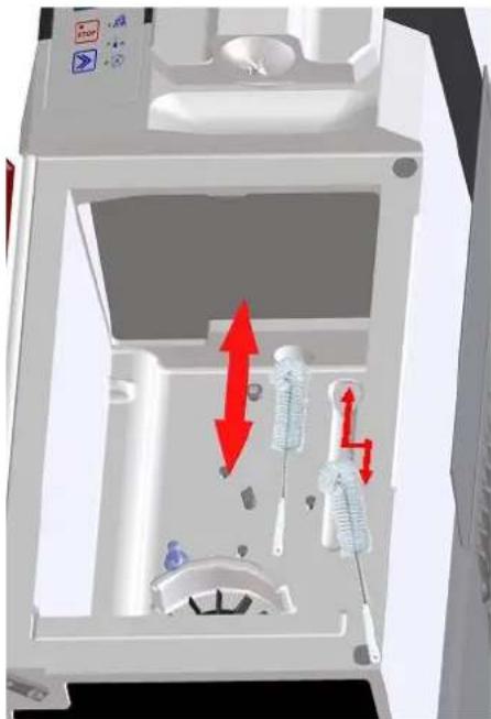
natural_image
3D diagram of a mechanical device interior with red directional arrows indicating movement or force (no text or symbols)- Clean all parts of the cylinder using a not abrasive sponge soaked with disinfectant solution.
- Clean the hole between the fridge and the cylinder with the brush soaked with disinfectant solution.
- Let the disinfectant solution work for 10/15 min.
- Remove the disinfectant from the cylinder and the hole between the fridge and the cylinder with care, using a sponge and the brush soaked with water.
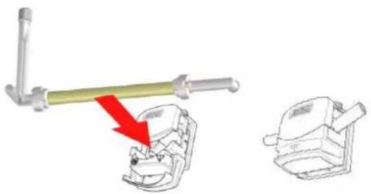
7.1.7 Assembly of product suction tube
To assemble the product suction tube, proceed as follows:
- Assemble the non-return valve (D) to the inlet pipe (C), then assembly the joint (C1) to the inlet pipe (C) as it is shown in the figure below.
It is advisable to use the O-ring extractor in order to assemble the non-return valve (D) easier.
Check the correct assembly of the non-return valve (D) and the joint.
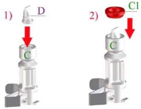
-Lubricate the inlet pipe joint (C1) with the supplied lubricant (C), introduce it into the hole between the fridge and the cylinder and block it with its subjection (A).
- assemble the pump body again: check the fitness between attachments, place the pump in its support and turn it clockwise to block it.
natural_image
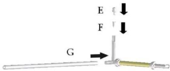
Three-step diagram showing a device's internal components and red arrows indicating rotation or assembly (no text or symbols)- Assemble on the joint suction pump tube (Z) the air inlet valve (F) and the air flow regulator (E). Then position in its seat the O-Ring of the joint (B) and assemble sequentially the joint (B), the bushing (X2) on the tube (Y). After fix the tube (Y) on the joint (Z) with the bushing (X1). Once assembled all, make sure that the result is as shown in figure.
- Lubricate the connection racor O-ring (B) with vaseline. Pull the subjection (A) to the left and introduce the connection racor (B) in the inlet pipe (C). Release the subjection (A) in order to block the connection racor (B).
- Introduce the product suction tube carefully into the peristaltic pump. The tube must not be twisted, too tense or pressed against the pump's compression rollers. Make sure that the tube is positioned in the centre of the compression rollers and close the lid of the pump.
natural_image
Technical illustration of a mechanical clamp tool interacting with a component, showing a red arrow indicating motion (no text or symbols present)
If, after the cleaning it is expected that the machine will not operate until the next day it is necessary to left the lid pump open. Therefore it is necessary to remember closing it before the next use.
- Place the product tank with its cover and level probe into the fridge again.
- Connect the level probe plug carefully to the tank cover.
natural_image
3D diagram of a kitchen sink with a black tool and red arrow indicating a downward motion (no text or symbols)-Replace the fridge top tray.
natural_image
Mechanical assembly diagram showing directional arrows (red and blue) indicating movement or force, no text or symbols present.7.1.8 Agitator assembly
To assemble the agitator proceed as follows:
- Insert the blade extension. Lubricate the shaft seal and introduce it through the agitator.
natural_image
3D rendering of a mechanical tool with a red arrow indicating direction (no text or symbols)
Cool the agitator before insert it into the cylinder
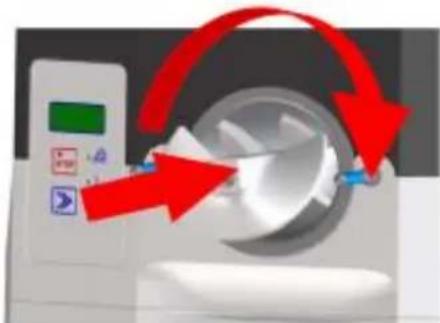
- Push the assembled agitator onto the cylinder and turn it clockwise until it is fixed in position with the drive shaft, if this is not properly fixed the tap body will not close and the mixture will come out through the cylinder.
natural_image
Illustration of a medical device with red arrows indicating rotation or change, no visible text or symbols7.1.9 Tap body assembly
To assemble the tap body proceed as follows:
-Lubricate and assemble both plunger (H) O-rings in its place.
- introduce the plunger (H) in its place taking care in align the plunger's square groove with the rectangular groove on the front of the tap body.
- Place the lever (G) in the tap body and introduce the pin (I) through the lever hole.
- Assemble the O-ring in the pin (I).
- Lubricate and place the tap body bolt (L) O-ring.
- Lubricate and place the reduction-to-star O-ring.
- Assembly the reduction-to-star (M).
-Lubricate and place the tap body rear O-ring.
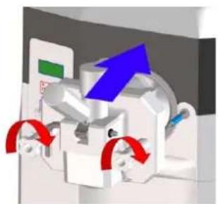
-Reassemble the machine's tap body by tightening both handles at time
natural_image
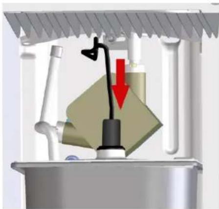
3D diagram of a mechanical device with blue and red directional arrows indicating motion or flow (no text or symbols)7.1.10 Final cycle of sanitizing and rinse of the machine
-Position in the cabinet the tank with 3L of sanitizing solution.
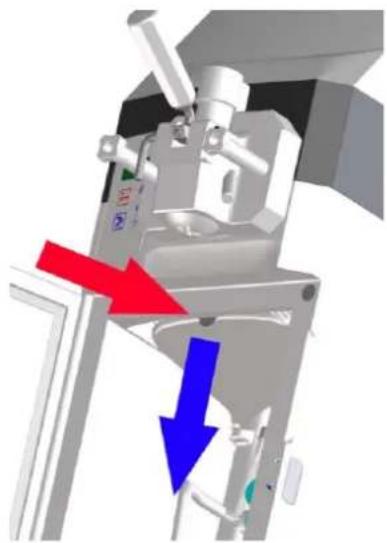
natural_image
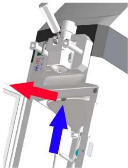
3D rendering of a mechanical device with a bucket and lid, no visible text or symbols-Remove the tap body bolt.
natural_image
3D rendering of a mechanical device with red and blue directional arrows indicating motion or force (no text or symbols)- Ensure that the tap dispensing lever is closed.
- Place a container under the tap body bolt hole.
- Start the clean/load/empty function. The machine starts to load the sanitizing solution into the churning cylinder.
- When a constant flow of sanitizing solution through the tap body hole bolt is observed, press stop key STOP.
-Close the tap body bolt hole by replacing the bolt.
natural_image
3D diagram of a mechanical device with directional arrows indicating motion or force (no text or symbols)-Leave to act the sanitizing solution for 15 minutes.
-Place a container under the tap dispensing and open the tap lever in order to let the sanitizing solution going out.
- Start the clean/load/empty function and wait that the machine pulls all the remaining sanitizer from the tank. If necessary, restart the clean/load/empty function.
- Make the rinse of the machine by repeating all the operations explained above, where instead of the sanitizer must be used clean water. Make at least 2 rinses.
- After the rinse, position a container under the tap dispensing and loosen the two handles of the tap in order to leave the rinse water going out completely from the cylinder of the machine.
7.2 Cleaning of fridge
To clean the fridge proceed as follows.
- Remove the fridge top tray. Press the tray retainer and remove it pulling downwards.
natural_image
3D mechanical assembly diagram showing a presser with red and blue directional arrows indicating movement (no text or symbols)-Remove the fridge bottom tray.
natural_image
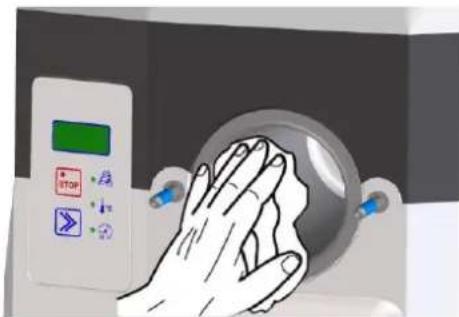
Diagram of a machine door with a red arrow pointing to the interior panel (no text or symbols present)- Clean the walls, floor and evaporator of the fridge with a sponge wet with drinking water. Cover the same areas using a sponge soaked with disinfectant solution and wait for 10/15 minutes. Carefully remove the disinfectant using a sponge wet with water and dry all parts of the fridge well, above all the evaporator blades inside the fridge.
natural_image
Illustration of a hand reaching toward a control panel with a green indicator light (no text or symbols visible)Clean both top and bottom trays, firstly, with water and then using a disinfectant solution. Wait for 10/15 minutes for it to act and rinse well with water, dry and replace it inside the fridge.
7.3 Cleaning of external drip tray
The external drip tray located under the product distribution tap should be emptied and cleaned daily.
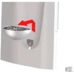
Lift the tray with its grid and remove it from its position by pulling it outwards.
natural_image
Close-up of a wall-mounted fan or vent with a red arrow indicating direction (no text or symbols)Wash the tray and the grid separately using tepid water. Dry all of the components. Replace the grid on the tray. Replace the tray in its position and press it downwards to fix it properly to the machine.
7.4 Cleaning of air filters
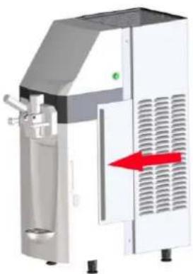
The air filters are located at both sides of the machine. They can be easily removed using the corresponding grip.
natural_image
Industrial machine with white housing and red directional arrow indicating flow or movement (no text or symbols visible)Remove the dirt and dust from the filters and replace the filters on the machine.

The machine's air filters must be cleaned regularly

Dirty air filters can place the machine's proper operation at risk.
7.5 Replacement of the product suction pump tube

It is advisable to replace the product suction pump tube every 3 months
The machine comes with a product suction pump tube kit.

The replacement of the suction tube must be made with the machine previously emptied.
1) - DISMANTLE THE PRODUCT SUCTION TUBE USED BY THE MACHINE
- Disconnect the level sensor connector by pulling upwards and remove the tank
natural_image
Mechanical device with a green block and black lever, showing internal components and a red upward arrow (no text or symbols)- Remove the fridge top tray. Press the tray retainer and remove it pulling downwards.
natural_image
3D mechanical assembly diagram showing a motor or actuator with red and blue directional arrows indicating motion (no text or symbols present)- Open the peristaltic pump by opening its lid.
natural_image
Diagram of a mechanical device with a red arrow indicating direction (no text or symbols)Extract the product suction tube by carefully removing it from the peristaltic pump.
natural_image
Mechanical assembly diagram showing a lever mechanism with a red arrow indicating motion (no text or symbols present)- Pull the inlet pipe subjection (A) to the left and extract the connection racor (B) from the inlet pipe (C).
-
Remove the used pump tube (G) from the valve connection pipe.
-
Extract the air flow regulator (E) and the air inlet valve (F) from the pump tube.
2) - ASSMEBLE A NEW PRODUCT SUCTION TUBE ON THE MACHINE
- Assemble in the suction tube, the pump tube the air inlet valve (F) and the air flow regulator (E).
- Lubricate the connection racor O-ring (B) with vaseline. Pull the subjection (A) to the left and introduce the connection racor (B) in the inlet pipe (C). Release the subjection (A) in order to block the connection racor (B).
- Introduce the product suction tube carefully into the peristaltic pump. The tube must not be twisted, too tense or pressed against the pump's compression rollers. Make sure that the tube is positioned in the centre of the compression rollers and close the lid of the pump.
natural_image
Technical illustration of a mechanical assembly with a lever and two views of a component (no text or symbols)- Place the product tank with its cover and level probe into the fridge again.
- Connect the level probe plug carefully to the tank cover.
natural_image
3D diagram of a kitchen sink with a valve and red arrow indicating a downward motion (no text or symbols)-Replace the fridge top tray

natural_image
Mechanical device with red and blue directional arrows indicating movement or force (no text or symbols)7.6 Periodic maintenance

The apparatus should be reviewed periodically, (at least once a year), by a specialized technician. This periodic verification serves to maintain a high level of safety of the machine and all of its installed components. In the case of a worn out component, it should be replaced with a new original replacement.

In the case of a faulty or worn out machine component the use of the machine is totally forbidden. It is forbidden for the operator to perform periodic maintenance.

8. DISPOSAL

Electrical and electronic equipment must be disposed of in accordance with the European Directive 2002/96/CE. This equipment CANNOT be eliminated like normal urban solid waste but should be independently collected to optimize the recuperation and recycling of manufactured materials.

The crossed off rubbish bin appears on all products as a reminder of the obligation to use selective waste collection. Properly considering all options relating to the disposal of old products will contribute to the protection of the environment
9. PROBLEM – CAUSES - SOLUTIONS
| ABNORMALITIES | CAUSES | SOLUTIONS |
| The machine will not turn on. | The plug is badly connected. | Check it and plug it in properly. |
| The compressor starts up and stops a few seconds later. | The air dos not circulate. | 1. Make sure that there is nothing resting on the machine, on top of the air vents.2. Clean the air filters if they are obstructed by dust or anything else. |
| The machine runs but ice-cream does not come out of the tap. | 1. Sugar is missing from the mixture.2. Water remained after cleaning and it has frozen inside the tap. | 1. Wait until the ice-cream in the cylinder melts, change and modify the mixture.2. Let it melt and then extract a tub of ice-cream before re-starting operation. |
| The machine operates but the ice-cream is soft. | 1. Too much sugar in the mixture.2. The machine has been operating for a long time without extracting ice-cream.3. The ice-cream was extracted too quickly. | 1. Modify or change the mixture.2. Extract ice-cream through the tap to renew the mixture in the cylinder.3. Remember not to exceed the recommended output rate, regulating -if necessary- the ice-cream output velocity. |
| Leaking of mixture or ice-cream above or below the plunger even though the tap is closed. | 1. Plunger mounted without the o-ring joint or the o-ring joint is broken. | 1. If it is missing put it in place and if it is broken replace it. |
| Mixture present in the dip tray inside the fridge. | 1. The gland is not assembled or it is damaged.2. Mixture came out of the deposit when it was filled. | 1. Assemble it if missing or replace it with a new one if damaged.2. Pay more attention to the tank filling phase |
| The output tap is hard to move, it is stiff. | 1. Sugar has dried on the plungers. | 1. Wash well and grease the plungers and o-ring joints using alimentary grease. |
| Ice-cream comes out of thetap body. | 1. The o-ring joints were not put in place or they are badly assembled.2. The handles are not fixed uniformly. | 1. Check and take the necessary action.2. Stop the machine, loosen them and tighten them again. |
10. ALARMS
The machine includes an automatic checking device that signals possible machine malfunctions. When an alarm appears on the display, check the table below to see which alarm has been activated. If the alarm is not very serious then the machine can be used for distribution; if the alarm is serious then the machine will not allow distribution. In this case press STOP and do not use the machine until it has been repaired. Press Select to delete the message and reset the alarm. The alarms are described on the following table:
| ALARMA | DESCRIPCIÓN |
| IMS | Door open (IMS). The machine stops. |
| A01 | Agitator motor disconnected/broken down |
| A05 | The fridge probe is malfunctioning (NTC). Only the Clean function can be accessed. The machine stops. |
| A06 | Means the cylinder probe is malfunctioning. |
| Pr | High pressure has been detected by the pressure switch. |
| A15 | Means that a cut of voltage has taken place while operating |
| A22 | During Production the agitator motor is examined and if it operates for over 15 minutes without reaching the ice-cream consistency then the machine automatically goes into reached consistency state with raised alarm A22. |
INHALTSVERZEICHNIS
natural_image
3D rendering of a laboratory instrument with labeled dimensions L, H, and P (no text or symbols on the device itself)2.4. Bedienfeld
5. INSTALLATION

natural_image
Illustration of a hand pouring liquid into a container with a stirring rod (no text or symbols)natural_image
3D rendering of a mechanical device with a cylindrical component and open door (no visible text or symbols)SL310011172 Ed 00_DE
natural_image
3D rendered mechanical assembly with labeled component 'M' (no readable text or symbols beyond label)
natural_image
3D diagram of a mechanical device with directional arrows indicating motion or force (no text or symbols)natural_image
Cross-sectional diagram of a mechanical device with internal components and a red arrow indicating a specific part (no text or symbols present)
natural_image
Illustration of a hand pressing a mechanical component on a base (no text or symbols visible)
natural_image
3D illustration of a mechanical device with blue and red directional arrows indicating motion or force (no text or symbols)natural_image
Medical imaging device with monitor, control panel, and red arrow indicating action (no text or symbols)natural_image
3D rendering of a mechanical tool with a red arrow indicating direction (no text or symbols)natural_image
Mechanical assembly diagram showing a valve mechanism with a red arrow indicating direction (no text or symbols present)natural_image
3D mechanical assembly diagram showing a motor or actuator with red and blue directional arrows indicating motion (no text or symbols present)natural_image
Illustration of a person using a computer mouse, showing the keyboard and mouse (no text or symbols)natural_image
Mechanical assembly diagram showing a lever and gear mechanism with red directional arrow (no text or symbols)natural_image
Two mechanical components with red arrows indicating rotational motion (no text or symbols)natural_image
Illustration of a hand pressing down on a circular device with control buttons (no text or symbols)natural_image
3D mechanical assembly diagram showing internal components with red arrows indicating movement or force (no text or symbols)natural_image
Three views of a black hard drive with red arrows indicating rotation or assembly (no text or symbols)natural_image
Technical illustration of a mechanical assembly with a lever and two views of a component (no text or symbols)
natural_image
Mechanical assembly diagram showing a valve mechanism with a red arrow indicating force or direction (no text or symbols present)natural_image
Mechanical assembly diagram showing directional arrows (red and blue) indicating movement or force, no readable text or symbols present.natural_image
3D mechanical component diagram showing a drill bit with red directional arrow (no text or symbols)natural_image
Medical imaging device with red arrows indicating rotation or change (no text or symbols)natural_image
Diagram of a medical device with blue and red directional arrows indicating movement or force (no text or symbols)SL310011172 Ed 00_DE
natural_image
3D rendering of a mechanical device with open door and internal components (no visible text or symbols)natural_image
3D diagram of a kitchen appliance with directional arrows indicating motion (no text or symbols)natural_image
3D diagram of a mechanical device with directional arrows indicating motion or force (no text or symbols)natural_image
Mechanical assembly diagram showing a motor or pump mechanism with red and blue directional arrows indicating motion (no text or symbols present)natural_image
Diagram of a door opening with a blue vent and red arrow pointing downward (no text or symbols)natural_image
Illustration of a hand reaching toward a control panel with a green indicator light (no text or symbols visible)natural_image
Close-up of a white appliance with a circular component and red directional arrows indicating motion (no text or symbols)natural_image
Exterior view of a modern industrial machine with a red arrow indicating flow or movement (no text or symbols visible)natural_image
Mechanical assembly diagram showing a valve mechanism with a red arrow indicating direction (no text or symbols present)natural_image
Mechanical assembly diagram showing a motor or actuator with red and blue directional arrows indicating motion (no text or symbols present)natural_image
Diagram of a mechanical device with a red curved arrow indicating motion or force (no text or symbols present)natural_image
Mechanical assembly diagram showing a lever and gear mechanism with red arrows indicating motion (no text or symbols)natural_image
Illustration of a mechanical tool interacting with a skull and a separate view of a helmet (no text or symbols present)natural_image
Diagram of a kitchen sink with a valve and pipe, showing a red downward arrow indicating a component (no text or symbols present)natural_image
Mechanical assembly diagram showing directional arrows (red and blue) indicating movement or force, no text or symbols present.9. ANOMALIES – CAUSES – SOLUTIONS
10. ALARMES
1. INFORMATIONS GÉNÉRALES
1.1. Fabricant
natural_image
3D rendering of a laboratory instrument with labeled dimensions L, H, and P (no text or symbols on the device itself)
5. INSTALLATION

natural_image
3D rendering of a white industrial machine with a bucket and lid, showing internal components and no visible text or symbols.
natural_image
3D mechanical assembly diagram showing a blue and white component with a labeled arrow 'M' pointing to a feature (no text or symbols beyond label)
natural_image
3D rendering of a mechanical device with red and blue directional arrows indicating motion or flow (no text or symbols)natural_image
3D diagram of a mechanical or industrial device with directional arrows indicating flow or movement (no text or symbols)MIN
MAX
natural_image
Cross-sectional diagram of a mechanical device with internal components and a red arrow indicating a specific part (no text or symbols present)
natural_image
Illustration of a hand reaching toward a mechanical device with no visible text or symbols
natural_image
3D rendering of a medical imaging machine with a red arrow pointing to a circular device (no text or symbols visible)natural_image
3D mechanical component with red arrow indicating direction, no visible text or symbolsnatural_image
Mechanical device with a lever and valve assembly, showing internal components and a red upward arrow (no text or symbols)natural_image
3D mechanical assembly diagram showing a motor or pump mechanism with red and blue directional arrows indicating motion (no text or symbols present)SL310011172 Ed 00_FR
natural_image
Illustration of a computer monitor with a red arrow indicating speed (no text or symbols)natural_image
Mechanical assembly diagram showing a lever and clamping mechanism with red arrows indicating motion (no text or symbols)natural_image
Two mechanical components with red arrows indicating rotation or assembly (no text or symbols)natural_image
3D rendering of a metallic cylindrical container with internal mechanical components (no text or symbols visible)natural_image
3D diagram of a spacecraft interior with astronaut and crew members, showing directional arrows (no text or symbols)natural_image
Three views of a black electronic device showing internal components and red arrows indicating rotation (no text or symbols)natural_image
Technical illustration of a mechanical assembly with a lever and two views of a component (no text or symbols)