
8443D - Drill MAKITA - Free user manual and instructions
Find the device manual for free 8443D MAKITA in PDF.

| Product Type | Cordless Hammer Drill |
| Brand | Makita |
| Model | 8443D |
| Rated Voltage | 18 V DC |
| Drilling Capacity (Concrete) | 16 mm |
| Drilling Capacity (Steel) | 13 mm |
| Drilling Capacity (Wood) | 30 mm |
| No Load Speed (High Speed) | 0 - 1,400 min⁻¹ |
| No Load Speed (Low Speed) | 0 - 450 min⁻¹ (estimated from blows per minute) |
| Blows per Minute (High Speed) | 0 - 21,000 min⁻¹ |
| Blows per Minute (Low Speed) | 0 - 6,750 min⁻¹ |
| Overall Length | 267 mm |
| Net Weight (with Battery) | 2.6 kg |
| Power Source | 18 V Lithium-ion battery (model not included) |
| Chuck | Keyless (Sleeve type) |
| Operating Modes | Rotation only, hammering, screwdriving with clutch (16 torque positions) |
| Reverse Switch | Yes (with neutral position) |
| Variable Speed Trigger | Yes (trigger controlled) |
| Mechanical Gear Change | 2 speeds (high and low) |
| Side Handle | Yes, 360° adjustable |
| Depth Stop | Yes, adjustable |
| Maintenance | Carbon brush replacement with wear indicator |
| Safety | Battery lock, reverse switch in neutral position, insulation of metal parts |
| Supplied Accessories | Side handle, depth stop, cleaning bulb, bit holder |
Frequently Asked Questions - 8443D MAKITA
User questions about 8443D MAKITA
0 question about this device. Answer the ones you know or ask your own.
Ask a new question about this device
Download the instructions for your Drill in PDF format for free! Find your manual 8443D - MAKITA and take your electronic device back in hand. On this page are published all the documents necessary for the use of your device. 8443D by MAKITA.
USER MANUAL 8443D MAKITA
natural_image
Line drawing of a power drill with a spoke and control panel (no text or symbols)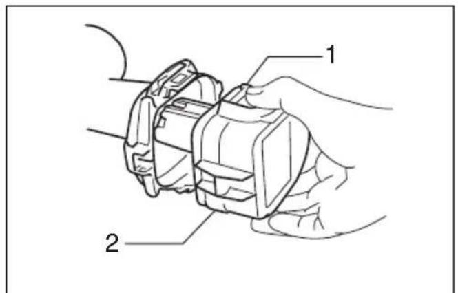
1
2
3
4
5
6
7
8
9
10
natural_image
Line drawing of a screwdriver tip falling into water (no text or symbols)11 12
natural_image
Illustration of a hand holding a tool with arrows indicating motion or force (no text or symbols)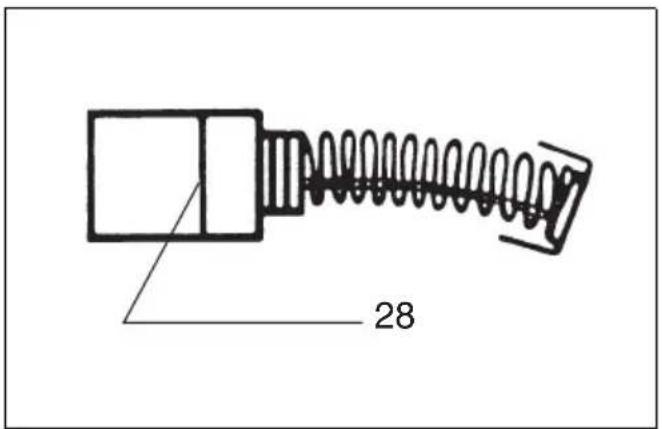
13 14
15
ENGLISH
| Explanation of general view | ||
| 1 Push button | 11 Speed change lever | 21 Teeth |
| 2 Battery cartridge | 12 Action mode changing ring | 22 Side grip |
| 3 Switch trigger | 13 Arrow | 23 Loosen |
| 4 Reversing switch lever | 14 Adjusting ring | 24 Depth rod |
| 5 A side | 15 Graduations | 25 Thumb screw |
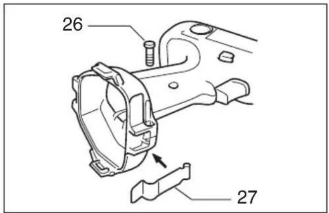
| 6 B side | 16 Tighten | 26 Screw |
| 7 Clockwise | 17 Sleeve | 27 Set plate |
| 8 Counterclockwise | 18 Bit | 28 Limit mark |
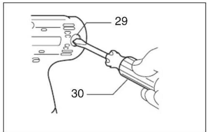
| 9 Low speed | 19 Bit holder | 29 Brush holder cap |
| 10 High speed | 20 Grip base | 30 Screwdriver |
SPECIFICATIONS
Model 8413D 8433D 8443D
| Capacities | |||
| Concrete | 13 mm 14mm 16 mm | ||
| Steel | 13 mm 13 mm 13 mm | ||
| Wood | 30 mm 36 mm 38 mm | ||
| Wood screw | 6 mm x 75 mm 6 mm x 75 mm 10 mm x 90 mm | ||
| Machine screw | 6 mm 6 mm 6 mm | ||
| No load speed (min ^-1 ) | |||
| High | 0-1,300 | 0-1,300 | 0-1,400 |
| Low | 0-400 | 0-400 | 0-450 |
| Blows per minute | |||
| High | 0-19,500 | 0-19,500 | 0-21,000 |
| Low | 0-6,000 | 0-6,000 | 0-6,750 |
| Overall length | 267 mm | 267 mm | 267 mm |
| Net weight (with battery cartridge) | 2.3 kg | 2.4 kg | 2.6 kg |
| Rated voltage | D.C. 12 V | D.C. 14.4 V | D.C. 18 V |
- Due to our continuing program of research and development, the specifications herein are subject to change without notice.
- Note: Specifications may differ from country to country.
Safety hints
For your own safety, please refer to the enclosed safety instructions.
IMPORTANT SAFETY INSTRUCTIONS FOR CHARGER & BATTERY CARTRIDGE
- SAVE THESE INSTRUCTIONS — This manual contains important safety and operating instructions for battery charger.
- Before using battery charger, read all instructions and cautionary markings on (1) battery charger, (2) battery, and (3) product using battery.
- CAUTION — To reduce risk of injury, charge only MAKITA type rechargeable batteries. Other types of batteries may burst causing personal injury and damage.
- Do not expose charger to rain or snow.
- Use of an attachment not recommended or sold by the battery charger manufacturer may result in a risk of fire, electric shock, or injury to persons.
-
To reduce risk of damage to electric plug and cord, pull by plug rather than cord when disconnecting charger.
-
Make sure cord is located so that it will not be stepped on, tripped over, or otherwise subjected to damage or stress.
- Do not operate charger with damaged cord or plug — replace them immediately.
- Do not operate charger if it has received a sharp blow, been dropped, or otherwise damaged in any way; take it to a qualified serviceman.
- Do not disassemble charger or battery cartridge; take it to a qualified serviceman when service or repair is required. Incorrect reassembly may result in a risk of electric shock or fire.
- To reduce risk of electric shock, unplug charger from outlet before attempting any maintenance or cleaning. Turning off controls will not reduce this risk.
- The battery charger is not intended for use by young children or infirm persons without supervision.
- Young children should be supervised to ensure that they do not play with the battery charger.
ADDITIONAL SAFETY RULES FOR CHARGER & BATTERY CARTRIDGE
-
Do not charge battery cartridge when temperature is BELOW 10^ C ( 50^ F) or ABOVE 40^ C ( 104^ F).
-
Do not attempt to use a step-up transformer, an engine generator or DC power receptacle.
-
Do not allow anything to cover or clog the charger vents.
-
Always cover the battery terminals with the battery cover when the battery cartridge is not used.
-
Do not short the battery cartridge:
(1) Do not touch the terminals with any conductive material.
(2) Avoid storing battery cartridge in a container with other metal objects such as nails, coins, etc.
(3) Do not expose battery cartridge to water or rain.
A battery short can cause a large current flow, overheating, possible burns and even a breakdown.
-
Do not store the tool and battery cartridge in locations where the temperature may reach or exceed 50^ C ( 122^ F).
-
Do not incinerate the battery cartridge even if it is severely damaged or is completely worn out. The battery cartridge can explode in a fire.
-
Be careful not to drop, shake or strike battery.
-
Do not charge inside a box or container of any kind. The battery must be placed in a well ventilated area during charging.
ADDITIONAL SAFETY RULES FOR TOOL
- Be aware that this tool is always in an operating condition, because it does not have to be plugged into an electrical outlet.
- Always be sure you have a firm footing. Be sure no one is below when using the tool in high locations.
- Hold the tool firmly.
- Keep hands away from rotating parts.
- When drilling into walls, floors or wherever "live" electrical wires may be encountered, DO NOT TOUCH ANY METAL PARTS OF THE TOOL! Hold the tool only by the insulated grasping surfaces to prevent electric shock if you drill into a "live" wire.
- Do not leave the tool running. Operate the tool only when hand-held.
- Do not touch the drill bit or the workpiece immediately after operation; they may be extremely hot and could burn your skin.
SAVE THESE INSTRUCTIONS.
OPERATING INSTRUCTIONS
Installing or removing battery cartridge (Fig. 1)
- Always switch off the tool before insertion or removal of the battery cartridge.
- To remove the battery cartridge, withdraw it from the tool while pressing the buttons on both sides of the cartridge.
- To insert the battery cartridge, align the tongue on the battery cartridge with the groove in the housing and slip it into place. Always insert it all the way until it locks in place with a little click. If not, it may accidentally fall out of the tool, causing injury to you or someone around you.
- Do not use force when inserting the battery cartridge. If the cartridge does not slide in easily, it is not being inserted correctly.
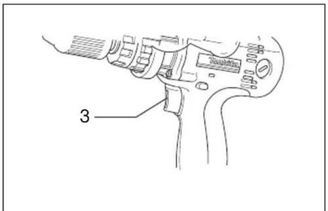
Switch action (Fig. 2)
CAUTION:
Before inserting the battery cartridge into the tool, always check to see that the switch trigger actuates properly and returns to the "OFF" position when released.
To start the tool, simply pull the trigger. tool speed is increased by increasing pressure on the trigger. Release the trigger to stop.
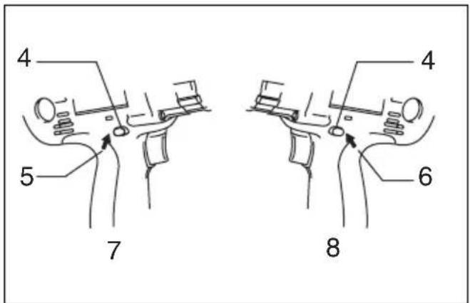
Reversing switch action (Fig. 3)
CAUTION:
- Always check the direction of rotation before operation.
- Use the reversing switch only after the tool comes to a complete stop. Changing the direction of rotation before the tool stops may damage the tool.
- When not operating the tool, always set the reversing switch lever to the neutral position.
This tool has a reversing switch to change the direction of rotation. Depress the reversing switch lever from the A side for clockwise rotation or from the B side for counterclockwise rotation. When the switch lever is in the neutral position, the switch trigger cannot be pulled.
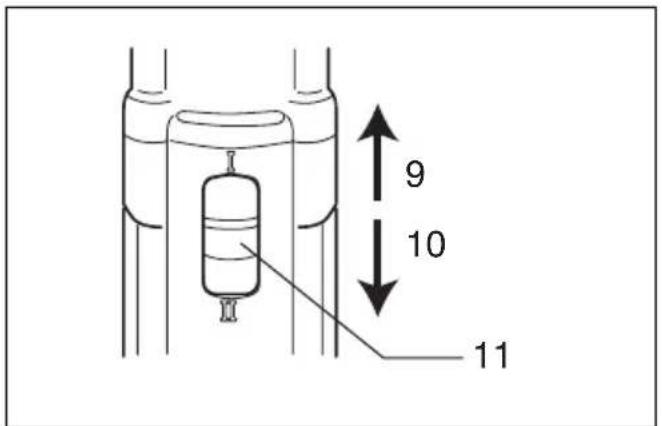
Speed change (Fig. 4)
To change the speed, first switch off the tool and then slide the speed change lever to the “II” side for high speed or “I” side for low speed. Be sure that the speed change lever is set to the correct position before operation. Use the right speed for your job.
CAUTION:
- Always set the speed change lever fully to the correct position. If you operate the tool with the speed change lever positioned half-way between the “I” side and “II” side, the tool may be damaged.
- Do not use the speed change lever while the tool is running. The tool may be damaged.
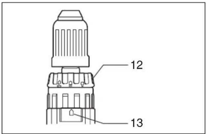
Selecting the action mode (Fig. 5)
This tool employs an action mode changing ring. Select one of the three modes suitable for your work needs by using this ring. For rotation only, turn the ring so that the arrow on the tool body points toward the mark on the ring. For rotation with hammering, turn the ring so that the arrow points toward the on the ring. For rotation with clutch, turn the ring so that the arrow points toward the mark on the ring.
CAUTION:
Always set the ring correctly to your desired mode mark. If you operate the tool with the ring positioned half-way between the mode marks, the tool may be damaged.
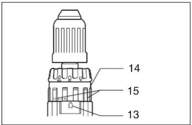
Adjusting the fastening torque (Fig. 6)
The fastening torque can be adjusted in 16 steps by turning the adjusting ring so that its graduations are aligned with the arrow on the tool body. The fastening torque is minimum when the number 1 is aligned with the arrow, and maximum when thenumber 16 is aligned with the arrow.
Before actual operation, drive a trial screw into your material or a piece of duplicate material to determine which torque level is required for a particular application.
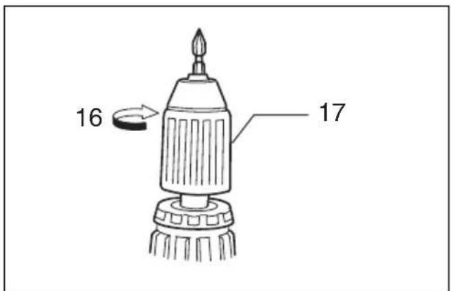
Installing or removing driver bit or drill bit (Fig. 7 & 8)
Important:
Always be sure that the tool is switched off and the battery cartridge is removed before installing or removing the bit.
Turn the sleeve counterclockwise to open the chuck jaws. Place the bit in the chuck as far as it will go. Turn the sleeve clockwise to tighten the chuck. To remove the bit, turn the sleeve counterclockwise.
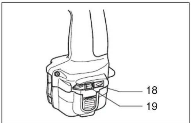
When not using the driver bit, keep it in the bit holders. Bits 45 mm long can be kept there.
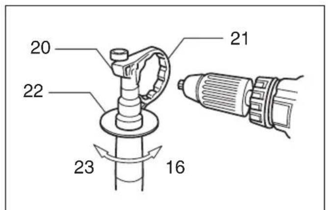
Side grip (auxiliary handle) (Fig. 9)
Always use the side grip to ensure operating safety. Install the side grip so that the teeth on the grip fit in between the protrusions on the tool barrel. Then tighten the grip by turning clockwise at the desired position. It may be swung 360° so as to be secured at any position.
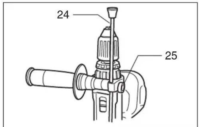
Adjustable depth rod (Fig. 10)
The adjustable depth rod is used to drill holes of uniform depth. Loosen the thumb screw, set to desired position, then tighten the thumb screw.
Screwdriving operation (Fig. 11)
First, turn the action mode changing ring so that the arrow on the tool body points to the marking. Adjust the adjusting ring to the proper torque level for your work. Then proceed as follows.
Place the point of the driver bit in the screw head and apply pressure to the tool. Start the tool slowly and then increase the speed gradually. Release the trigger as soon as the clutch cuts in.
NOTE:
- Make sure that the driver bit is inserted straight in the screw head, or the screw and/or bit may be damaged.
- When driving wood screws, predrill pilot holes to make driving easier and to prevent splitting of the workpiece. See the chart below.
| Nominal diameter of wood screw (mm) | Recommended size of pilot hole (mm) |
| 3.1 2.0 – 2.2 | |
| 3.5 2.2 – 2.5 | |
| 3.8 2.5 – 2.8 | |
| 4.5 2.9 – 3.2 | |
| 4.8 3.1 – 3.4 | |
| 5.1 3.3 – 3.6 | |
| 5.5 3.6 – 3.9 | |
| 5.8 4.0 – 4.2 | |
| 6.1 4.2 – 4.4 |
- If the tool is operated continuously until the battery cartridge has discharged, allow the tool to rest for 15 minutes before proceeding with a fresh battery.
Drilling operation
First, turn the action mode changing ring so that the arrow on the tool body points to the ≈marking. The adjusting ring can be aligned in any torque levels for this operation. Then proceed as follows.
- Drilling in wood
When drilling in wood, best results are obtained with wood drills equipped with a guide screw. The guide screw makes drilling easier by pulling the bit into the workpiece.
- Drilling in metal
To prevent the bit from slipping when starting a hole, make an indentation with a centerpunch and hammer at the point to be drilled. Place the point of the bit in the indentation and start drilling. Use a cutting lubricant when drilling metals. The exceptions are iron and brass which should be drilled dry.
CAUTION:
- Pressing excessively on the tool will not speed up the drilling. In fact, this excessive pressure will only serve to damage the tip of your bit, decrease the tool performance and shorten the service life of the tool.
- There is a tremendous force exerted on the tool/bit at the time of hole breakthrough. Hold the tool firmly and exert care when the bit begins to break through the workpiece.
- A stuck bit can be removed simply by setting the reversing switch to reverse rotation in order to back out. However, the tool may back out abruptly if you do not hold it firmly.
- Always secure small workpieces in a vise or similar hold-down device.
- If the tool is operated continuously until the battery cartridge has discharged, allow the tool to rest for 15 minutes before proceeding with a fresh battery.
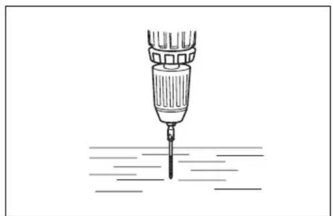
Hammer drilling operation
First, turn the action mode changing ring so that the arrow on the tool body points to the marking. The adjusting ring can be aligned in any torque levels for this operation. Position the bit at the desired location for the hole, then pull the trigger. Do not force the tool. Light pressure gives best results. Keep the tool in position and prevent it from slipping away from the hole. Do not apply more pressure when the hole becomes clogged with chips or particles. Instead, run the tool at an idle, then remove the bit partially from the hole. By repeating this several times, the hole will be cleaned out and normal drilling may be resumed.
CAUTION:
There is a tremendous and sudden twisting force exerted on the tool/bit at the time of hole breakthrough, when the hole becomes clogged with chips and particles, or when striking reinforcing rods embedded in the concrete. Always use the side grip (auxiliary handle) and firmly hold the tool by both side grip and switch handle during operations. Failure to do so may result in the loss of control of the tool and potentially severe injury.
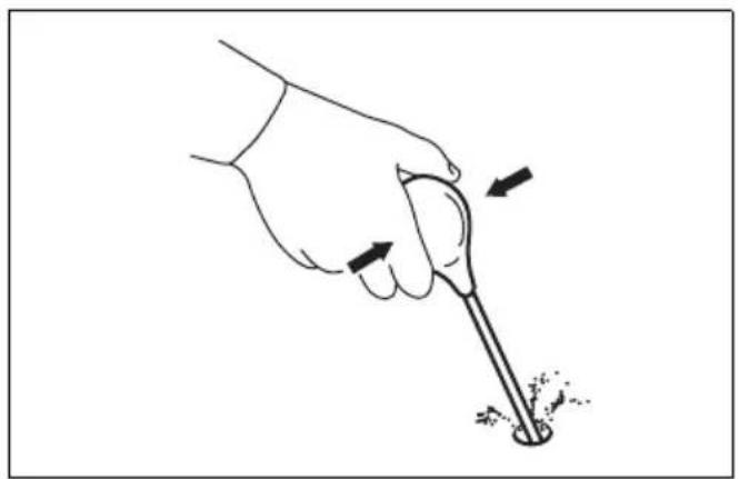
Blow-out bulb (Fig. 12)
Use the blow-out bulb to clean out the hole.
Installing set plate (Fig. 13)
For 8413D
Always install the set plate when using battery cartridges 1200, 1202 or 1202A. Install the set plate on the tool with the screw provided.
MAINTENANCE
CAUTION:
Always be sure that the tool is switched off and the battery cartridge is removed before carrying out any work on the tool.
Replacement of carbon brushes (Fig. 14 & 15)
Replace carbon brushes when they are worn down to the limit mark. Both identical carbon brushes should be replaced at the same time.
To maintain product safety and reliability, repairs, maintenance or adjustment should be carried out by Makita Authorized Service Center.
Descriptif
These accessories or attachments are recommended for use with your Makita tool specified in this manual. The use of any other accessories or attachments might present a risk of injury to persons. The accessories or attachments should be used only in the proper and intended manner.
F ACCESSOIRES
ATTENTION:
- Use bit No. 1 when fastening machine screws M3, or wood screws 2.1 ~mm - 2.7 ~mm .
- Use bit No. 2 when fastening machine screws M4 – M5, or wood screws 3.1 mm – 4.8 mm.
- Use bit No. 3 when fastening machine screws M6 – M8, or wood screws 5.1 mm – 6.4 mm.
Note :
The typical A-weighted sound pressure level is 83 dB (A). The noise level under working may exceed 85 dB (A).
- Wear ear protection. -
The typical weighted root mean square acceleration value is 8 m/s^2 .
FRANÇAISE
Bruit et vibrations
EC-DECLARATION OF CONFORMITY
The undersigned, Masahiro Yamaguchi, authorized by Makita Manufacturing Europe Ltd., Road 7, Hortonwood Industrial Estate, Telford, Shropshire TF1 4GP, United Kingdom declares that this product
(Serial No.: series production)
manufactured by Makita Corporation Europe Ltd is in compliance with the following standards or standardized documents.
EN50260, EN55014
in accordance with Council Directives, 89/336/EEC and 98/37/EC.
FRANÇAISE
DÉCLARATION DE CONFORMITÉ CE
Michigan Drive, Tongwell, Milton Keynes,
Bucks MK15 8JD, ENGLAND
PORTUGUÊS
EU-DEKLARATION OM KONFORMITET
Undertegnede, Masahiro Yamaguchi, med fuldmagt fra Makita Manufacturing Europe Ltd., Road 7, Hortonwood Industrial Estate, Telford, Shropshire TF1 4GP, United Kingdom, erklærer hermed, at dette produkt
(Løbenummer: serieproduktion)
Michigan Drive, Tongwell, Milton Keynes, Bucks MK15 8JD, ENGLAND
ENGLISH
EC-DECLARATION OF CONFORMITY
The undersigned, Yasuhiko Kanzaki, authorized by Kao Lung Tamura Electronics Co., Ltd. No. 4 Industry 1st Street, Ping Tung Industry District Chiao Nan Li, Ping Tung City, Taiwan declares that this battery charger
(Serial No.: series production)
manufactured by Kao Lung Tamura Electronics Co., Ltd. in Taiwan is in compliance with the following standards or standardized documents,
in accordance with Council Directives, 73/23/EEC and 89/336/EEC.
FRANÇAISE
DÉCLARATION DE CONFORMITÉ CE
EU-DEKLARATION OM KONFORMITET
Undertegnede, Yasuhiko Kanzaki, med fuldmagt fra Kao Lung Tamura Electronics Co., Ltd. No. 4 Industry 1st Street, Ping Tung Industry District Chiao Nan Li, Ping Tung City, Taiwan, erklærer hermed, at dette batteriopladeren
(Løbenummer: serieproduktion)
Michigan Drive, Tongwell, Milton Keynes,
Bucks MK15 8JD, ENGLAND