
DJS161 - Scissors MAKITA - Free user manual and instructions
Find the device manual for free DJS161 MAKITA in PDF.

| Product Type | Cordless Scissors |
| Brand | Makita |
| Model | DJS161 |
| Total Length | 362 mm |
| Net Weight (with battery) | 1.8 kg (BL1815N/BL1820) or 2.0 kg (BL1830/BL1840/BL1850) |
| Power Source | 18V lithium-ion battery, compatible with Makita 18V series batteries |
| Max. cutting capacity (steel up to 400 N/mm²) | 1.6 mm |
| Max. cutting capacity (steel up to 600 N/mm²) | 1.2 mm |
| Max. cutting capacity (aluminum up to 200 N/mm²) | 2.5 mm |
| Min. cutting radius | 250 mm |
| Number of impacts per minute | 4,300 /min |
| Rated voltage | DC 18V |
| Standard battery | BL1815N / BL1820 / BL1830 / BL1840 / BL1850 |
| Blade clearance adjustment | Yes, using a hex key and a thickness gauge |
| Lubrication | Required before and during use |
| Lockable switch | Yes, for continuous operation |
| Battery protection system | Overload, overheat, and deep discharge protection |
| Accidental restart prevention | Yes, with indicator light |
| Brush replacement | Yes, with wear limit mark |
| Blade life (mild steel 1.6 mm) | Approximately 200 meters |
| Warranty | 1 year limited |
| Included accessories | Hex key, thickness gauge, center blade, and side blades |
| Recommended use | Cutting sheet metal, steel, aluminum, sheet materials |
Frequently Asked Questions - DJS161 MAKITA
User questions about DJS161 MAKITA
0 question about this device. Answer the ones you know or ask your own.
Ask a new question about this device
Download the instructions for your Scissors in PDF format for free! Find your manual DJS161 - MAKITA and take your electronic device back in hand. On this page are published all the documents necessary for the use of your device. DJS161 by MAKITA.
USER MANUAL DJS161 MAKITA
MANUEL D'INSTRUCTION
Cordless Metal Shear
Cisaille sans Fil
natural_image
Technical line drawing of a mechanical component with no visible text or symbols010096
ENGLISH (Original instructions)
SPECIFICATIONS
| Model | DJS161 | DJS101 | |
| Max. cutting capacities | Steel up to 400 N/mm2 1.6 mm (16 ga) 1.0 mm (20 ga) | ||
| Steel up to 600 N/mm2 1.2 mm (18 ga) 0.7 mm (23 ga) | |||
| Aluminum up to 200 N/mm2 2.5 mm (13 ga) 2.5 mm (12 ga) | |||
| Min. cutting radius 250 mm (9 - 7/8") 30 mm (1 - 3/16") | |||
| Strokes per minute 4,300 /min | |||
| Overall length 362 mm (14 - 1/4") 364 mm (14 - 3/8") | |||
| Net weight | BL1815N / BL1820 1.8 kg (4.0 lbs) | ||
| BL1830 / BL1840 / BL1850 2.0 kg (4.4 lbs) | |||
| Rated voltage D.C. 18 V | |||
| Standard battery cartridge BL1815N / BL1820 / BL1830 / BL1840 / BL1850 | |||
- Due to our continuing program of research and development, the specifications herein are subject to change without notice.
- Specifications and battery cartridge may differ from country to country.
- Weight, with battery cartridge, according to EPTA-Procedure 01/2003
GEA006-2
General Power Tool Safety Warnings
⚠ WARNING Read all safety warnings and all instructions. Failure to follow the warnings and instructions may result in electric shock, fire and/or serious injury.
Save all warnings and instructions for future reference.
The term "power tool" in the warnings refers to your mains-operated (corded) power tool or battery-operated (cordless) power tool.
Work area safety
- Keep work area clean and well lit. Cluttered or dark areas invite accidents.
- Do not operate power tools in explosive atmospheres, such as in the presence of flammable liquids, gases or dust. Power tools create sparks which may ignite the dust or fumes.
- Keep children and bystanders away while operating a power tool. Distractions can cause you to lose control.
Electrical safety
- Power tool plugs must match the outlet. Never modify the plug in any way. Do not use any adapter plugs with earthed (grounded) power tools. Unmodified plugs and matching outlets will reduce risk of electric shock.
- Avoid body contact with earthed or grounded surfaces such as pipes, radiators, ranges and refrigerators. There is an increased risk of electric shock if your body is earthed or grounded.
-
Do not expose power tools to rain or wet conditions. Water entering a power tool will increase the risk of electric shock.
-
Do not abuse the cord. Never use the cord for carrying, pulling or unplugging the power tool. Keep cord away from heat, oil, sharp edges or moving parts. Damaged or entangled cords increase the risk of electric shock.
- When operating a power tool outdoors, use an extension cord suitable for outdoor use. Use of a cord suitable for outdoor use reduces the risk of electric shock.
- If operating a power tool in a damp location is unavoidable, use a ground fault circuit interrupter (GFCI) protected supply. Use of an GFCI reduces the risk of electric shock.
Personal safety
- Stay alert, watch what you are doing and use common sense when operating a power tool. Do not use a power tool while you are tired or under the influence of drugs, alcohol or medication. A moment of inattention while operating power tools may result in serious personal injury.
- Use personal protective equipment. Always wear eye protection. Protective equipment such as dust mask, non-skid safety shoes, hard hat, or hearing protection used for appropriate conditions will reduce personal injuries.
- Prevent unintentional starting. Ensure the switch is in the off-position before connecting to power source and/or battery pack, picking up or carrying the tool. Carrying power tools with your finger on the switch or energising power tools that have the switch on invites accidents.
-
Remove any adjusting key or wrench before turning the power tool on. A wrench or a key left attached to a rotating part of the power tool may result in personal injury.
-
Do not overreach. Keep proper footing and balance at all times. This enables better control of the power tool in unexpected situations.
- Dress properly. Do not wear loose clothing or jewellery. Keep your hair, clothing, and gloves away from moving parts. Loose clothes, jewellery or long hair can be caught in moving parts.
- If devices are provided for the connection of dust extraction and collection facilities, ensure these are connected and properly used. Use of dust collection can reduce dust-related hazards.
Power tool use and care
- Do not force the power tool. Use the correct power tool for your application. The correct power tool will do the job better and safer at the rate for which it was designed.
- Do not use the power tool if the switch does not turn it on and off. Any power tool that cannot be controlled with the switch is dangerous and must be repaired.
- Disconnect the plug from the power source and/or the battery pack from the power tool before making any adjustments, changing accessories, or storing power tools. Such preventive safety measures reduce the risk of starting the power tool accidentally.
- Store idle power tools out of the reach of children and do not allow persons unfamiliar with the power tool or these instructions to operate the power tool. Power tools are dangerous in the hands of untrained users.
- Maintain power tools. Check for misalignment or binding of moving parts, breakage of parts and any other condition that may affect the power tool's operation. If damaged, have the power tool repaired before use. Many accidents are caused by poorly maintained power tools.
- Keep cutting tools sharp and clean. Properly maintained cutting tools with sharp cutting edges are less likely to bind and are easier to control.
- Use the power tool, accessories and tool bits etc. in accordance with these instructions, taking into account the working conditions and the work to be performed. Use of the power tool for operations different from those intended could result in a hazardous situation.
Battery tool use and care
- Recharge only with the charger specified by the manufacturer. A charger that is suitable for one type of battery pack may create a risk of fire when used with another battery pack.
-
Use power tools only with specifically designated battery packs. Use of any other battery packs may create a risk of injury and fire.
-
When battery pack is not in use, keep it away from other metal objects, like paper clips, coins, keys, nails, screws or other small metal objects, that can make a connection from one terminal to another. Shorting the battery terminals together may cause burns or a fire.
- Under abusive conditions, liquid may be ejected from the battery; avoid contact. If contact accidentally occurs, flush with water. If liquid contacts eyes, additionally seek medical help. Liquid ejected from the battery may cause irritation or burns.
Service
- Have your power tool serviced by a qualified repair person using only identical replacement parts. This will ensure that the safety of the power tool is maintained.
- Follow instruction for lubricating and changing accessories.
- Keep handles dry, clean and free from oil and grease.
GEB067-1
CORDLESS SHEAR SAFETY WARNINGS
- Hold the tool firmly.
- Secure the workpiece firmly.
- Keep hands away from moving parts.
- Edges and chips of the workpiece are sharp. Wear gloves. It is also recommended that you put on thickly bottomed shoes to prevent injury.
- Do not put the tool on the chips of the workpiece. Otherwise it can cause damage and trouble on the tool.
- Do not leave the tool running. Operate the tool only when hand-held.
- Always be sure you have a firm footing. Be sure no one is below when using the tool in high locations.
- Do not touch the blade or the workpiece immediately after operation; they may be extremely hot and could burn your skin.
- Avoid cutting electrical wires. It can cause serious accident by electric shock.
SAVE THESE INSTRUCTIONS.
WARNING:
DO NOT let comfort or familiarity with product (gained from repeated use) replace strict adherence to safety rules for the subject product. MISUSE or failure to follow the safety rules stated in this instruction manual may cause serious personal injury.
USD301-1
Symbols
The followings show the symbols used for tool.
| v | · volts |
| ... | · direct current |
| no | · no load speed |
| .../minr/min | · revolutions or reciprocation per minute |
ENC007-8
IMPORTANT SAFETY INSTRUCTIONS
FOR BATTERY CARTRIDGE
- Before using battery cartridge, read all instructions and cautionary markings on (1) battery charger, (2) battery, and (3) product using battery.
- Do not disassemble battery cartridge.
- If operating time has become excessively shorter, stop operating immediately. It may result in a risk of overheating, possible burns and even an explosion.
- If electrolyte gets into your eyes, rinse them out with clear water and seek medical attention right away. It may result in loss of your eyesight.
- Do not short the battery cartridge:
(1) Do not touch the terminals with any conductive material.
(2) Avoid storing battery cartridge in a container with other metal objects such as nails, coins, etc.
(3) Do not expose battery cartridge to water or rain.
A battery short can cause a large current flow, overheating, possible burns and even a breakdown.
- Do not store the tool and battery cartridge in locations where the temperature may reach or exceed 50^ C ( 122^ F).
- Do not incinerate the battery cartridge even if it is severely damaged or is completely worn out. The battery cartridge can explode in a fire.
- Be careful not to drop or strike battery.
- Do not use a damaged battery.
- Follow your local regulations relating to disposal of battery.
SAVE THESE INSTRUCTIONS.
Tips for maintaining maximum battery life
- Charge the battery cartridge before completely discharged. Always stop tool operation and charge the battery cartridge when you notice less tool power.
- Never recharge a fully charged battery cartridge. Overcharging shortens the battery service life.
- Charge the battery cartridge with room temperature at 10^ C - 40^ C ( 50^ F - 104^ F). Let a hot battery cartridge cool down before charging it.
- Charge the battery cartridge once in every six months if you do not use it for a long period of time.
FUNCTIONAL DESCRIPTION
CAUTION:
• Always be sure that the tool is switched off and the battery cartridge is removed before adjusting or checking function on the tool.
Installing or removing battery cartridge
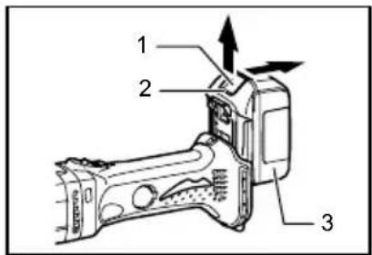
- Button
- Red indicator
- Battery cartridge
014129
CAUTION:
- Always switch off the tool before installing or removing of the battery cartridge.
- Hold the tool and the battery cartridge firmly when installing or removing battery cartridge. Failure to hold the tool and the battery cartridge firmly may cause them to slip off your hands and result in damage to the tool and battery cartridge and a personal injury.
To remove the battery cartridge, slide it from the tool while sliding the button on the front of the cartridge.
To install the battery cartridge, align the tongue on the battery cartridge with the groove in the housing and slip it into place. Insert it all the way until it locks in place with a little click. If you can see the red indicator on the upper side of the button, it is not locked completely.
CAUTION:
• Always install the battery cartridge fully until the red indicator cannot be seen. If not, it may accidentally fall out of the tool, causing injury to you or someone around you.
- Do not install the battery cartridge forcibly. If the cartridge does not slide in easily, it is not being inserted correctly.
Battery protection system
The tool is equipped with a battery protection system. This system automatically cuts off power to the motor to extend battery life.
The tool will automatically stop during operation if the tool and/or battery are placed under one of the following conditions:
• Overloaded:
The tool is operated in a manner that causes it to draw an abnormally high current.
In this situation, turn the tool off and stop the application that caused the tool to become
overloaded. Then turn the tool on to restart. If the tool does not start, the battery is overheated. In this situation, let the battery cool before turning the tool on again.
- Low battery voltage:
The remaining battery capacity is too low and the tool will not operate. In this situation, remove and recharge the battery.
NOTE:
The overheat protection works only with a battery cartridge with a star mark.
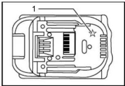
- Star marking
012128
Switch action
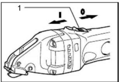
- Switch lever
010088
CAUTION:
- Before inserting the battery cartridge into the tool, always check to see that the switch lever actuates properly and returns to the "OFF" position when the rear of the switch lever is depressed.
- Switch can be locked in "ON" position for ease of operator comfort during extend use. Apply caution when locking tool in "OFF" position and maintain firm grasp on tool.
To start the tool, slide the switch lever toward the "I (ON)" position. For continuous operation, press the front of the switch lever to lock it.
To stop the tool, press the rear of the switch lever, then slide it toward the "O (OFF)" position.
Indication lamp with multi function
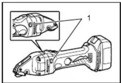
natural_image
Technical line drawing of a mechanical component with an inset showing a close-up detail (no text or symbols present)- Indicating lamp
010100
Indication lamps are located in two positions.
- Battery cartridge replacing signal
- When the battery power is almost used up during operation, the red lamp lights up and the tool stops immediately. Replace the battery with fully charged one when the red lamp lights up.
- Accidental re-start preventive function
- Even if the battery cartridge is inserted on the tool with the slide switch in the "I (ON)" position, the tool does not start. At this time, the lamp flickers slowly and this shows that the accidental re-start preventive function is at work.
- To start the tool, first slide the slide switch toward the "O (OFF)" position and then slide it toward the "I (ON)" position.
ASSEMBLY
CAUTION:
• Always be sure that the tool is switched off and the battery cartridge is removed before carrying out any work on the tool.
Adjusting the blade clearance
For DJS161 only
Adjust the clearance between the side blade and the center blade according to the thickness of the workpiece.
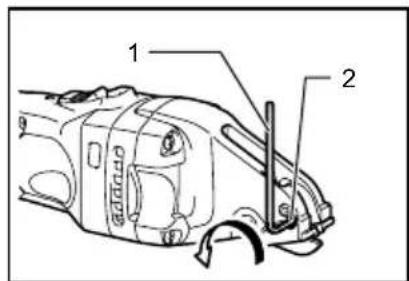
- Hex wrench
- Screw
010085
First use a hex wrench to loosen the screw.
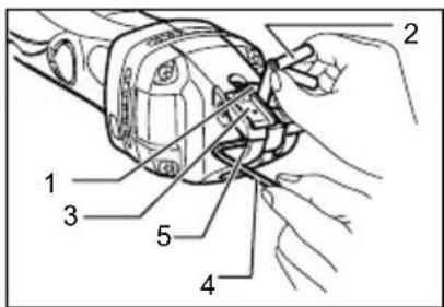
-
Center blade
-
Thickness gauge
-
Side blade
-
Hex wrench
-
Hex socket head bolt
010086
Then use the hex wrench to adjust the clearance by tightening or loosening the bolt. There may be a slight difference between clearance of both sides of the center blade.
Check the smaller clearance with the thickness gauge and adjust it.
When using the thickness gauge to adjust the blade clearance, refer to the table.
| Workpiece thickness (mm) Marking on thickness gauge | |
| Less than 0.8 0.5 | |
| 0.8 - 1.3 1.0 | |
| More than 1.3 | 1.5 |
006428
After adjusting the clearance, tighten the screw securely.
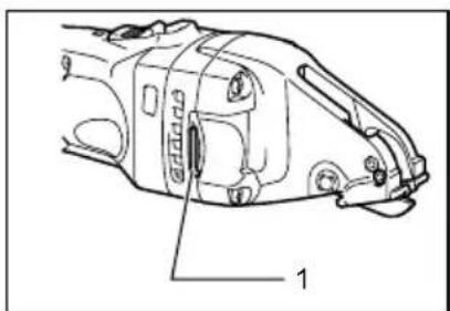
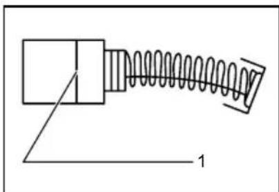
Storing hex wrench
natural_image
Technical line drawing of a mechanical component with labeled parts (no text or symbols present)- Hex wrench
010087
Store the hex wrench as shown in the figure when not in use.
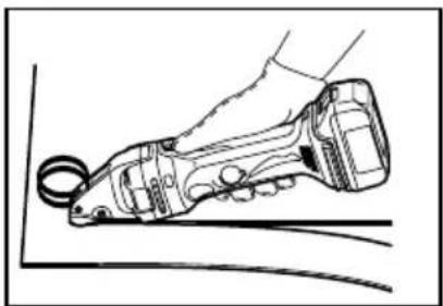
OPERATION
Lubrication
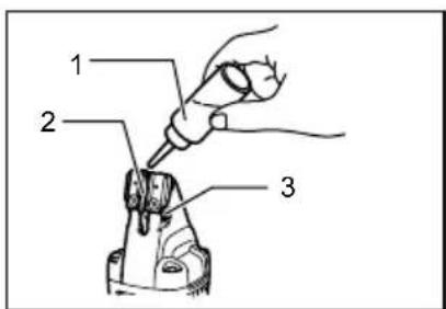
- Oil supply
- Center blade
- Pin
010084
Before operation, lubricate the contact point of the center blade and the pin. To keep good cutting performance, also use a cutting lubricant from time to time during operation.
OPERATION
natural_image
Line drawing of a hand using a power tool to grip a curved surface (no text or symbols)010098
Turn the tool on and set front ends of the side blades on the workpiece. Now simply move the tool forward, keeping the side blades flush with the workpiece surface.
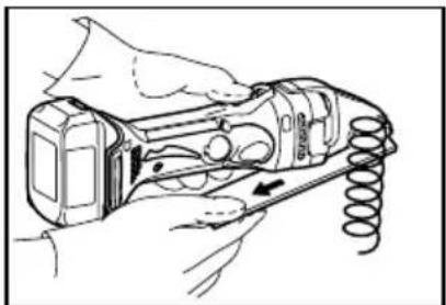
natural_image
Technical line drawing of a mechanical device with internal components and a coiled spring (no text or symbols)010099
CAUTION:
- When cutting a small portion of the workpiece, you may have difficulty completing the end of the cut. In that case, try to cut it again, pulling the workpiece back slightly.
MAINTENANCE
CAUTION:
• Always be sure that the tool is switched off and the battery cartridge is removed before attempting to perform inspection or maintenance.
NOTICE:
- Never use gasoline, benzine, thinner, alcohol or the like. Discoloration, deformation or cracks may result.
The tool and its air vents have to be kept clean. Regularly clean the tool's air vents or whenever the vents start to become obstructed.
Replacing carbon brushes
natural_image
Pure mechanical diagram of a spring-loaded component with no text or symbols- Limit mark
001145
Remove and check the carbon brushes regularly. Replace when they wear down to the limit mark. Keep the carbon brushes clean and free to slip in the holders. Both carbon brushes should be replaced at the same time. Use only identical carbon brushes.
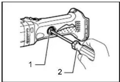
Insert the top end of slotted bit screwdriver into the notch in the tool and remove the holder cap cover by lifting it up.
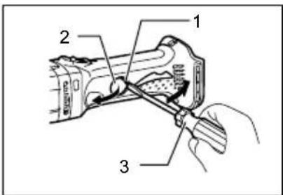
010092
- Brush holder cover
- Notch
- Screwdriver
Use a screwdriver to remove the brush holder caps. Take out the worn carbon brushes, insert the new ones and secure the brush holder caps.
010093
- Brush holder cap
- Screwdriver
Reinstall the holder cap cover on the tool.
Replacing blades
The service life of the blades varies in terms of the workpiece to be cut. The following reference tables indicate the approximate service life of the blades. When the blades become dull, ask Makita Authorized Service Centers to replace the blades.
For DJS161
| Material | Cutting thickness (mm) | Life of blades (m) |
| Mild steel plate (SPCC) | 2001.6 | |
| Stainless steel plate (SUS304) | 1.2 | 150 |
| Aluminum plate (A-5052) | 4002.5 |
010094
For DJS101
| Material | Cutting thickness (mm) | Life of blades (m) |
| Mild steel plate (SPCC) | 1201.0 | |
| Stainless steel plate (SUS304) | 0.7 | 50 |
010739
To maintain product SAFETY and RELIABILITY, repairs, any other maintenance or adjustment should be performed by Makita Authorized or Factory Service Centers, always using Makita replacement parts.
OPTIONAL ACCESSORIES
CAUTION:
• These accessories or attachments are recommended for use with your Makita tool specified in this manual. The use of any other accessories or attachments might present a risk of injury to persons. Only use accessory or attachment for its stated purpose.
If you need any assistance for more details regarding these accessories, ask your local Makita Service Center.
- Thickness gauge
- Center blade
- Side blade R
- Side blade L
- Hex wrench
- Makita genuine battery and charger
NOTE:
- Some items in the list may be included in the tool package as standard accessories. They may differ from country to country.
MAKITA LIMITED ONE YEAR WARRANTY
Warranty Policy
Every Makita tool is thoroughly inspected and tested before leaving the factory. It is warranted to be free of defects from workmanship and materials for the period of ONE YEAR from the date of original purchase. Should any trouble develop during this one year period, return the COMPLETE tool, freight prepaid, to one of Makita's Factory or Authorized Service Centers. If inspection shows the trouble is caused by defective workmanship or material, Makita will repair (or at our option, replace) without charge.
This Warranty does not apply where:
• repairs have been made or attempted by others:
• repairs are required because of normal wear and tear:
• the tool has been abused, misused or improperly maintained:
• alterations have been made to the tool.
IN NO EVENT SHALL MAKITA BE LIABLE FOR ANY INDIRECT, INCIDENTAL OR CONSEQUENTIAL DAMAGES FROM THE SALE OR USE OF THE PRODUCT. THIS DISCLAIMER APPLIES BOTH DURING AND AFTER THE TERM OF THIS WARRANTY.
MAKITA DISCLAIMS LIABILITY FOR ANY IMPLIED WARRANTIES, INCLUDING IMPLIED WARRANTIES OF "MERCHANTABILITY" AND "FITNESS FOR A SPECIFIC PURPOSE," AFTER THE ONE YEAR TERM OF THIS WARRANTY.
This Warranty gives you specific legal rights, and you may also have other rights which vary from state to state. Some states do not allow the exclusion or limitation of incidental or consequential damages, so the above limitation or exclusion may not apply to you. Some states do not allow limitation on how long an implied warranty lasts, so the above limitation may not apply to you.
EN0006-1
natural_image
Technical line drawing of a mechanical component with an inset showing a close-up detail (no text or symbols)- Lampe indicatrice
010100
- Clé hexagonale
- Vis
010085
natural_image
Technical line drawing of a mechanical component with labeled parts (no readable text or symbols)- Clé hexagonale
010087
natural_image
Line drawing of a hand using a power tool to grip a curved surface (no text or symbols)010098
natural_image
Technical line drawing of a handheld device with internal components and a coiled spring (no text or symbols)010099
ATTENTION:
natural_image
Pure mechanical diagram showing a spring-loaded component with no text or symbols- Bouchon de porte-charbon
- Tournevis
010093
natural_image
Technical line drawing of a mechanical component with an inset showing a close-up view of internal parts (no text or symbols present)- Llave hexagonal
- Tornillo
010085
natural_image
Technical line drawing of a mechanical component with labeled parts (no readable text or symbols)- Llave hexagonal
010087
natural_image
Line drawing of a hand holding a tool with a circular grip, resting on a surface (no text or symbols)010098
natural_image
Line drawing of a handheld device with coiled spring and hand holding it (no text or symbols)010099
⚠PRECAUCIÓN:
natural_image
Pure mechanical diagram of a spring-loaded component with no text or symbols- Marca límite
001145
010092
010093
Some dust created by power sanding, sawing, grinding, drilling, and other construction activities contains chemicals known to the State of California to cause cancer, birth defects or other reproductive harm. Some examples of these chemicals are:
- lead from lead-based paints,
• crystalline silica from bricks and cement and other masonry products, and
• arsenic and chromium from chemically-treated lumber.
Your risk from these exposures varies, depending on how often you do this type of work. To reduce your exposure to these chemicals: work in a well ventilated area, and work with approved safety equipment, such as those dust masks that are specially designed to filter out microscopic particles.
3-11-8, Sumiyoshi-cho,
Anjo, Aichi 446-8502 Japan

- Cordless Metal Shear
- Cisaille sans Fil
- ENGLISH (Original instructions)
- General Power Tool Safety Warnings
- Save all warnings and instructions for future reference.
- Work area safety
- Electrical safety
- Personal safety
- Power tool use and care
- Battery tool use and care
- Service
- CORDLESS SHEAR SAFETY WARNINGS
- SAVE THESE INSTRUCTIONS.
- WARNING:
- Symbols
- IMPORTANT SAFETY INSTRUCTIONS
- FOR BATTERY CARTRIDGE
- Tips for maintaining maximum battery life
- FUNCTIONAL DESCRIPTION
- CAUTION:
- Installing or removing battery cartridge
- Battery protection system
- NOTE:
- Switch action
- Indication lamp with multi function
- - Battery cartridge replacing signal
- - Accidental re-start preventive function
- ASSEMBLY
- Adjusting the blade clearance
- For DJS161 only
- Storing hex wrench
- OPERATION
- Lubrication
- MAINTENANCE
- NOTICE:
- Replacing carbon brushes
- Replacing blades
- OPTIONAL ACCESSORIES
- MAKITA LIMITED ONE YEAR WARRANTY
- Warranty Policy
- ATTENTION:
- ⚠PRECAUCIÓN:
Brand : MAKITA
Model : DJS161
Category : Scissors