LIFT50 - Wall mount OmniMount - Free user manual and instructions
Find the device manual for free LIFT50 OmniMount in PDF.
| Product Type | Wall mount for flat screen |
| Brand | OmniMount |
| Model | LIFT50 |
| Category | Wall mount |
| Maximum weight capacity | 22.7 kg (50 lb) |
| VESA compatibility | Up to 400 x 400 mm |
| Height adjustment | Yes, continuously adjustable |
| Tilt | Forward and backward |
| Rotation | Not specified |
| Materials | Sturdy steel |
| Color | Black |
| Warranty | 5 years against material and workmanship defects |
| Dimensions (approx.) | 60 x 30 x 5 cm (W x H x D) |
| Mount weight | 4 kg (approx.) |
| Main features | Height adjustment, tilt, integrated cable management |
| Care and cleaning | Clean with a soft, dry cloth. Do not use abrasive products. |
| Safety | Installation on wood stud or solid concrete wall. Load capacity multiplied by 4 for safety. |
| Spare parts and repairability | Contact customer service for spare parts. 5-year warranty. |
| General information | Wall mount designed for flat screens. Easy installation with included hardware. |
Frequently Asked Questions - LIFT50 OmniMount
User questions about LIFT50 OmniMount
0 question about this device. Answer the ones you know or ask your own.
Ask a new question about this device
Download the instructions for your Wall mount in PDF format for free! Find your manual LIFT50 - OmniMount and take your electronic device back in hand. On this page are published all the documents necessary for the use of your device. LIFT50 by OmniMount.
USER MANUAL LIFT50 OmniMount
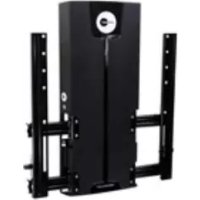
natural_image
Exterior view of a black ergonomic device with mounting brackets and a circular dial (no readable text or symbols)INSTRUCTION MANUAL
MANUEL D'INSTRUCTIONS
BENUTZERHANDBUCH
INSTRUCTIEHANDLEIDING
MANUAL DE INSTRUÇÕES
BRUGERVEJLEDNING
ASENNUSOPAS
MONTERINGSANVISNING
MANUAL CU
NAVODILA
Max screen size: 50"
Max weight 50 lbs - 22.7 kg
CAUTION: DO NOT EXCEED
OR PROPERTY DAMAGE MAY
OCCUR!

Reduce.Reuse.Recycle
NEED HELP? PLEASE CALL
REIKIA PAGALBOS? SKAMBINKITE
POTREBUJETE POMOC? PROSÍM, VOLAJTE
НУЖНА ПОМОЩЬ? ЗВОНИТЕ
YARDIM MI LAZIM? LÜTFEN BIZI ARAYIN
TRENGER DU HJELP? RING OSS
您需要帮助吗?请致电
ご質問がある場合は、お電話ください
1-800-MOUNT-IT (USA ONLY)

text_image
M ÁLJON! KAA'ESTE STE (SEE/ONE)DISCLAIMER - WARNING INFORMATION
Disclaimer – OmniMount Systems, Inc. has extended every effort to ensure to accuracy and completeness of this manual. However, OmniMount Systems, Inc. does not claim that the information covers all installation or operational variables. The information contained in this document is subject to change without notice or obligation of any kind. Regarding the information contained herein, OmniMount Systems, Inc. makes no representation of warranty, expressed or implied, and assumes no responsibility for accuracy, sufficiency, or completeness of the information contained in this document.
Wall Mounts
WARNING: FAILURE TO READ, THOROUGHLY UNDERSTAND, AND FOLLOW ALL INSTRUCTIONS CAN RESULT IN SERIOUS PERSONAL INJURY, DAMAGE TO PERSONAL PROPERTY, OR VOIDING OF FACTORY WARRANTY!
It is the responsibility of the installer to ensure all components are properly assembled and installed using the instructions provided. If you do not understand these instructions or have any questions or concerns, please contact customer service at 1-800-668-6848 or info@omnimount.com.
Do not attempt to install or assemble this product if the product or hardware is damaged or missing. In the event that replacement parts or hardware are needed, please contact Customer Service at 1-800-668-6848 or info@omnimount.com. International customers needing assistance should contact the Dealer from which they purchased the product.
The included hardware is designed for use on vertical walls constructed of wood studs or solid concrete. A wood stud wall is defined as consisting of a minimum of 2x4 wooden studs (2" wide by 4" deep) with a maximum of 5/8" drywall. The included hardware is not designed for use with metal studs or cinderblock walls. If you're uncertain about the construction of your wall, then please consult a qualified contractor or installer for assistance. For a safe installation, the wall you are mounting to must support 4 times the weight of the total load. If not, then the surface must be reinforced to meet this standard. The installer is responsible for verifying that the wall structure and hardware used in any installation method will safely support the total load.
ESPAÑOL
text_image
30-50 LBS 13.6 - 22.7 KGCAUTION!
MAXIMUM SCREEN SIZE

text_image
40-50"USE WITH FLAT PANELS EXCEEDING THE MAXIMUM WEIGHT CAPACITY OF THIS PRODUCT MAY RESULT IN PRODUCT FAILURE CAUSING POSSIBLE INJURY AND OR PROPERTY DAMAGE.
EL USO CON TELEVISORES DE PANTALLA PLANA CUYO PESO EXCEDA LA CAPACIDAD MÁXIMA DEL PRODUCTO PUEDE OCASIONAR FALLAS EN ÉSTE Y CAUSAR LESIONES O DAÑOS MATERIALES.
SI VOUS UTILISEZ CE PRODUIT AVEC DES ÉCRANS PLATS DÉPASSANT LA CHARGE MAXIMALE AUTORISÉE, LE PRODUIT POURRAIT MAL FONCTIONNER, ENTRAÎNANT BLESSURES ET ENDOMMAGEMENT DE MATÉRIEL.
natural_image
Isometric illustration of a wooden block with visible grain texture and a diagonal line (no text or symbols)
natural_image
Simple diagonal line drawn on a plain background (no text or symbols)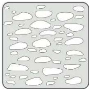
natural_image
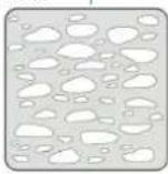
Abstract pattern of irregular white shapes on a gray background, no text or symbols present.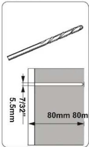
text_image
7/32" 5.5mm 80mm 80m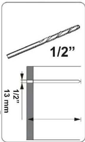
text_image
1/2" 1/2" 13 mm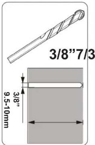
text_image
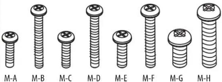
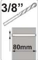
3/8"7/3 3/8" 9.5-10mmScrews / Hardware for Flat Panel
| Part # | Qty | Description |
| M-A 4 | Philips screws M4 x 15mm | |
| M-B 4 | Philips screws M4 x 30mm | |
| M-C 4 | Philips screws M5 x 15mm | |
| M-D 4 | Philips screws M5 x 30mm | |
| M-E 4 | Philips screws M6 x 15mm | |
| M-F 4 | Philips screws M6 x 30mm | |
| M-G 4 | Philips screws M8 x 15mm | |
| M-H 4 | Philips screws M8 x 30mm | |
| M-I 4 | Round Spacers: M6-M8 x 5mm | |
| M-J 4 | Round Spacers: M6-M8 x 10mm | |
| M-K 4 | Round Washers: M4-M5 | |
| M-L 4 | Round Washers: M6-M8 | |
Wall Kit
| Part # | Qty | Description |
| W-A 4 | Lag | Bolts (8mm x 80mm) |
| W-B 4 | Wall | Anchor (10mm OD x 8mm ID) |
Specialty Hardware
| Part # | Qty | Description |
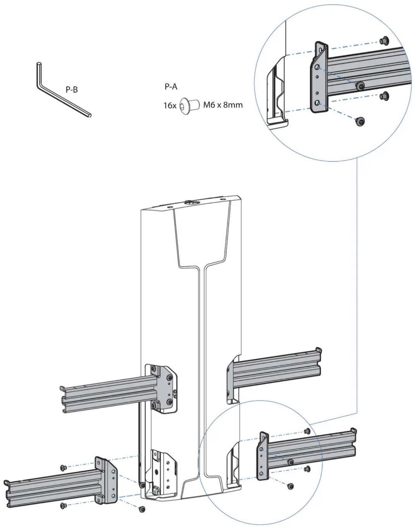
| P-A | 16 | Button Head Screw M6X8mm |
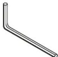
| P-B | 1 | 4mm Allen Wrench |
| P-C | 2 | Knob Screws M4x0.7" |
| M-M 4 | Pan | Head Screws M8x15mm |
| M-N | 4 | M8 Nylock Nut |
Cable Management/Hollow Wall
| Part # | Qty | Description |
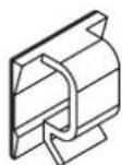
| 2 | Cable Clips | |
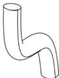
| 1 | Cable Tubing | |
| 4 | Cable Ties | |
| 2 | Snap Toggle Anchors | |
| W-C | 2 | 1/4-20 x 24mm Philips Screws |
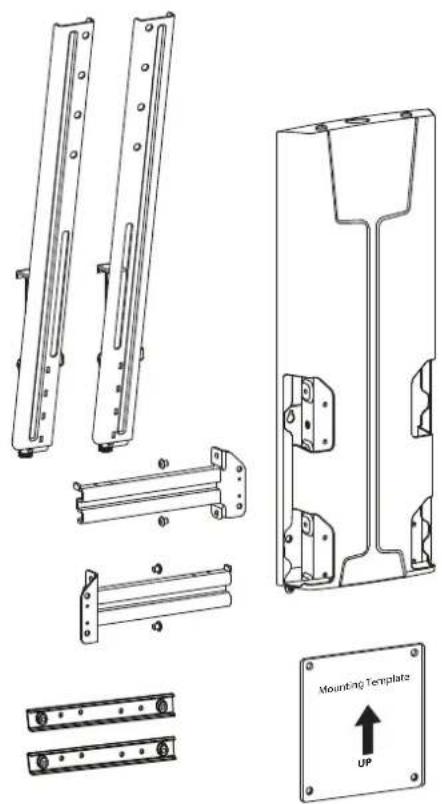
Contents
| Part # | Qty | Description |
| 1 | 2 | Vertical Rails |
| 2 | 2 | Left Horizontal Rails |
| 3 | 2 | Right Horizontal Rails |
| 4 | 2 | Tilt Tension Knob |
| 5 | 1 | Lift Assembly |
| 6 | 1 | Wall Template |
| 7 | 2 | 200mm x 200mm Adapter |
natural_image
Technical line drawings of mechanical components including brackets, mounting plate, and mounting bracket (no text or symbols)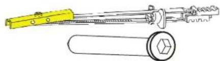
natural_image
Technical line drawing of a yellow tool and a cylindrical mechanical component (no text or symbols)W-C
text_image
M-A M-B M-C M-D M-E M-F M-G M-H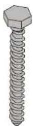
W-A
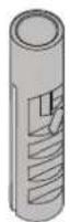
W-B
natural_image
Simple line drawing of a bent pipe or elbow joint (no text or symbols)P-B

M-1

M-J

M-K

M-M

M-N
16x

M6 x 8mm
2x

P-C
natural_image
Simple line drawing of a bent pipe or elbow joint (no text or symbols)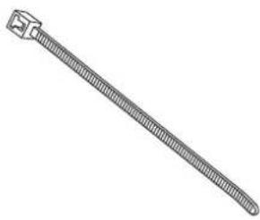
natural_image
Line drawing of a threaded cable or connector (no text or symbols)Attach monitor using monitor hardware, M-A, M-B, etc...
natural_image
Simple line drawing of a screwdriver inside a circle (no text or symbols)
text_image
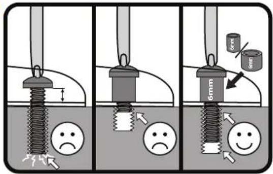
Diagram illustrating three stages of a mechanical or fluidic process with labeled components and visual indicators for stress or deformation.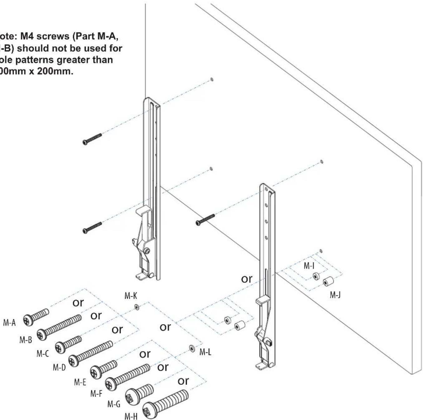
text_image
Note: M4 screws (Part M-A, -B) should not be used for ole patterns greater than 00mm x 200mm. or M-I M-J M-A M-B M-C M-D M-E M-F M-G M-HSTEP 1 - Option B (200mm x 200mm/Adapter Use)
Attach monitor using monitor hardware, M-A, M-B, etc...
text_image
Safety warning illustration showing a screwdriver detecting a negative symptom, with three scenarios of stress reduction and safety change.B.Attach Monitor
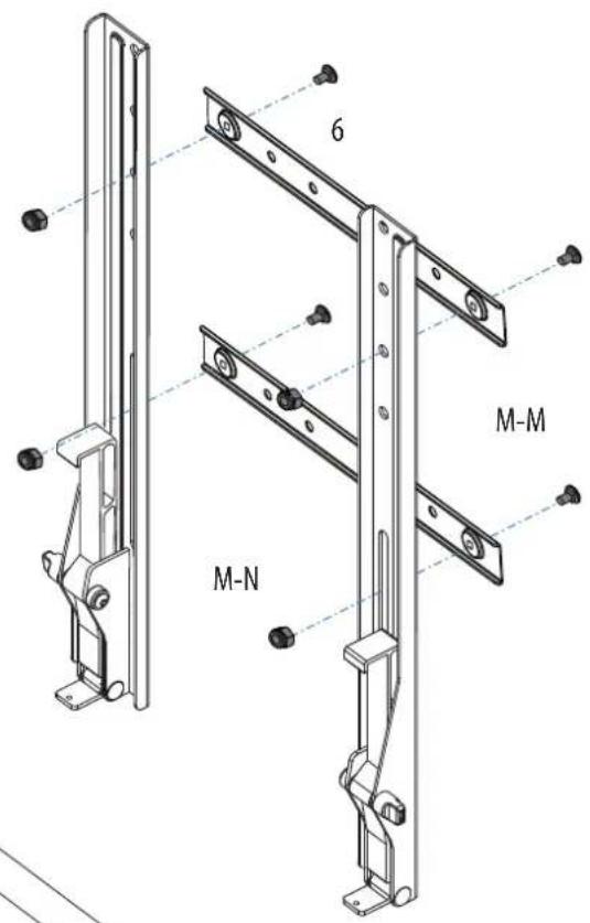
A. Attach Adapters to Vertical Rails
text_image
6 M-M M-N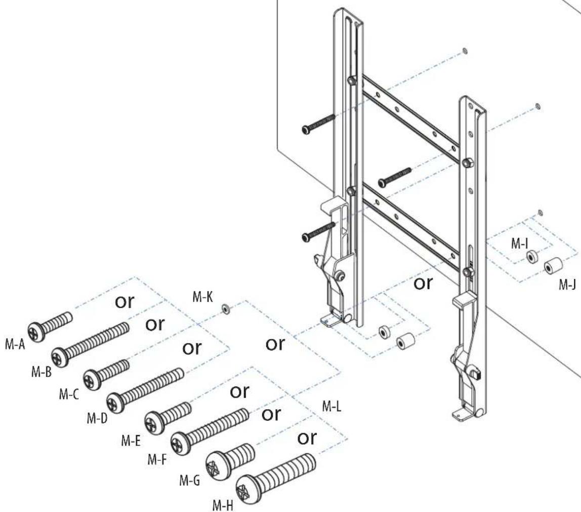
text_image
M-A M-B M-C M-D M-E M-F M-G M-H M-K or or or or or or or M-L M-I M-JDetermine Mounting Height

CAUTION: Before proceeding with this installation consult your TV product guide for manufacturer recommendations on choosing a mounting location that will ensure optimum TV performance. Location considerations might include: TV height and viewing angle - based on height and distance of seating, room dimensions and size of TV; access to power outlets; cable connections for speakers and other devices; protection from glare and heat, (windows, lamps, fireplace, air ducts) and vibration.
Please take into account that this product is being installed in it's highest position. Your TV will only be able to be lowered from it's installed position.
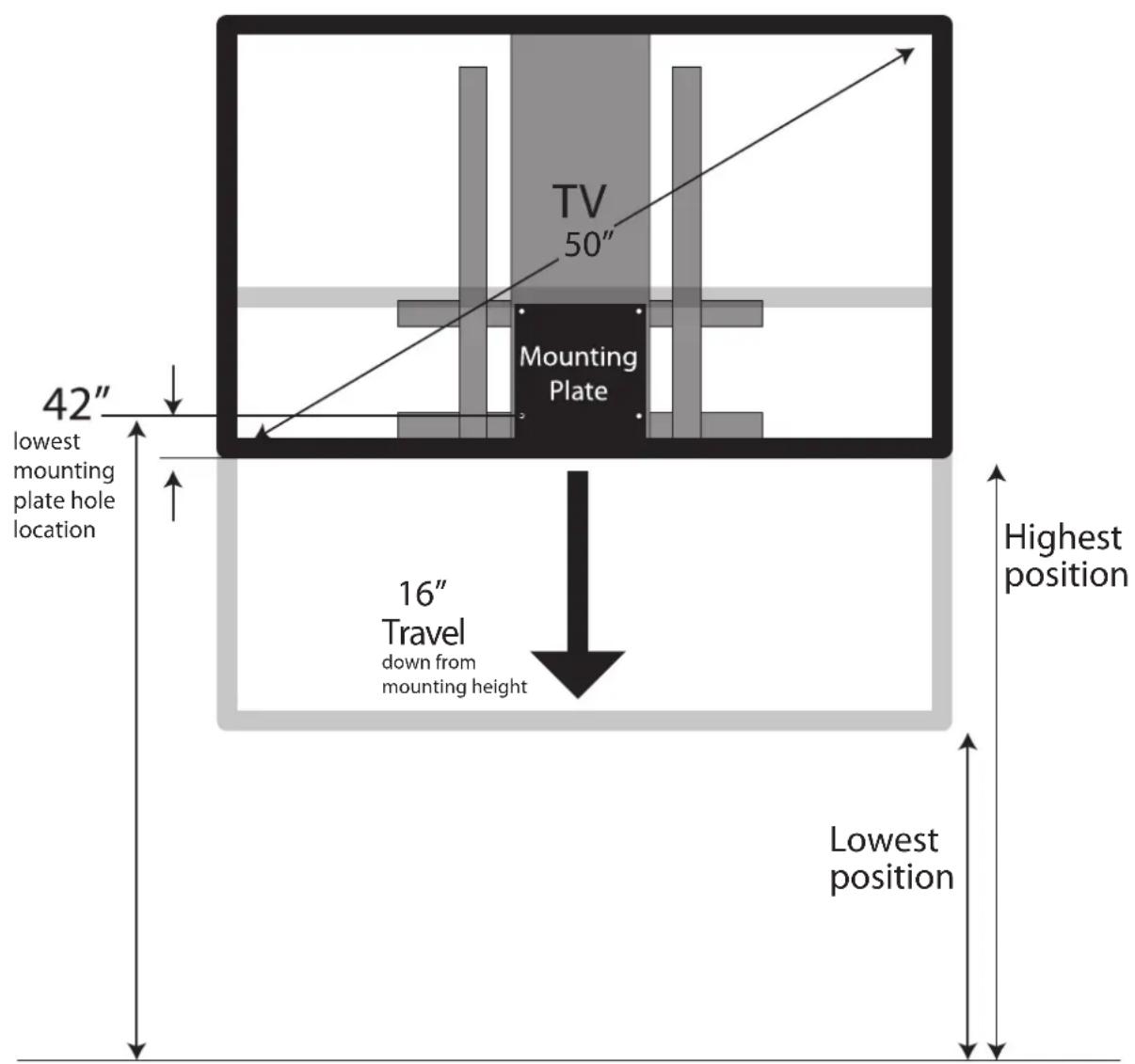
Due to the wide variety of flat screen televisions and interior design options, it is difficult to predict what your TV configuration will be. However, as a general guideline attach the mounting plate(bottom holes) 42" from floor for comfortable sit-stand viewing.
EXAMPLE: If mounting a 40" - 50" diagonal TV with centrally located VESA hole pattern, locate the lowest set of mounting plate holes 42" from floor.
You can modify the mounting height according to your TV size, VESA location and personal preference. For more information, please contact Ergotron Customer Care at 800-888-8458, www.ergotron.com
text_image
TV 50" Mounting Plate 42" lowest mounting plate hole location 16" Travel down from mounting height Highest position Lowest positionDetermine Mounting Height

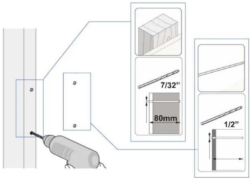
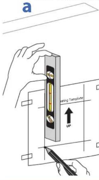
CAUTION: Before proceeding with this installation consult your TV product guide for manufacturer recommendations on choosing a mounting location that will ensure optimum TV performance. Location considerations might include: TV height and viewing angle - based on height and distance of seating, room dimensions and size of TV; access to power outlets; cable connections for speakers and other devices; protection from glare and heat, (windows, lamps, fireplace, air ducts) and vibration. Please take into account that this product is being installed in it's highest position. Your TV will only be able to be lowered from it's installed position. Drill 4 holes: 2 at stud and 2 at solid wall using appropriate bits.
a b
text_image
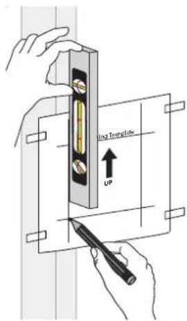
ing Template UPPlace template on wall so that it covers at least one wood stud and mark the mounting holes with a pencil.
text_image
7/32" 80mm 1/2"C
Insert wall anchors into wall (not wood stud).

natural_image
Simple vertical panel with two labeled points (① and ②) on the left side, no text or symbols inside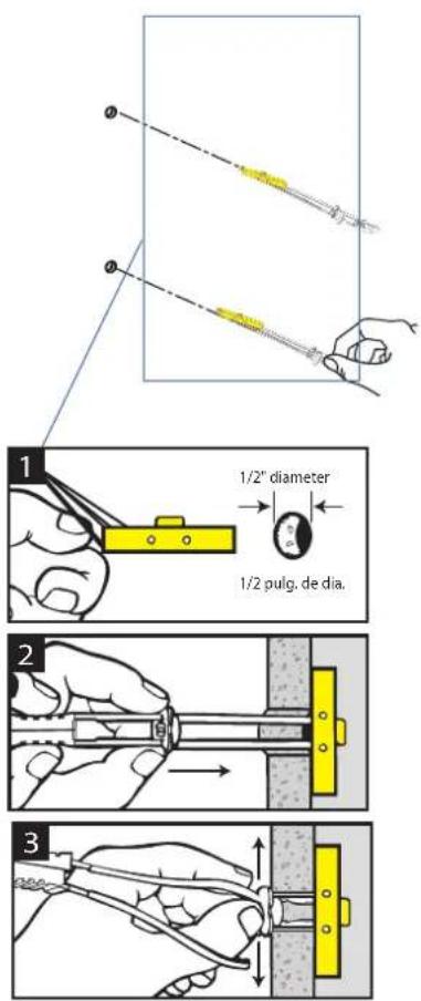
text_image
1/2" diameter 1/2 pulg. de dia.d
Install top two screws leaving about a 1/2" of room between the head of the screw and the wall.
text_image
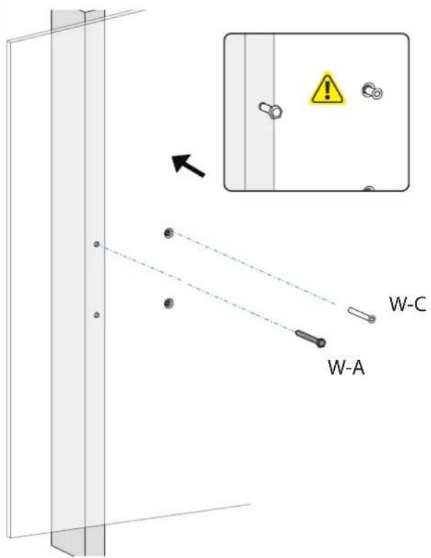
W-A W-C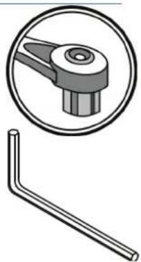
natural_image
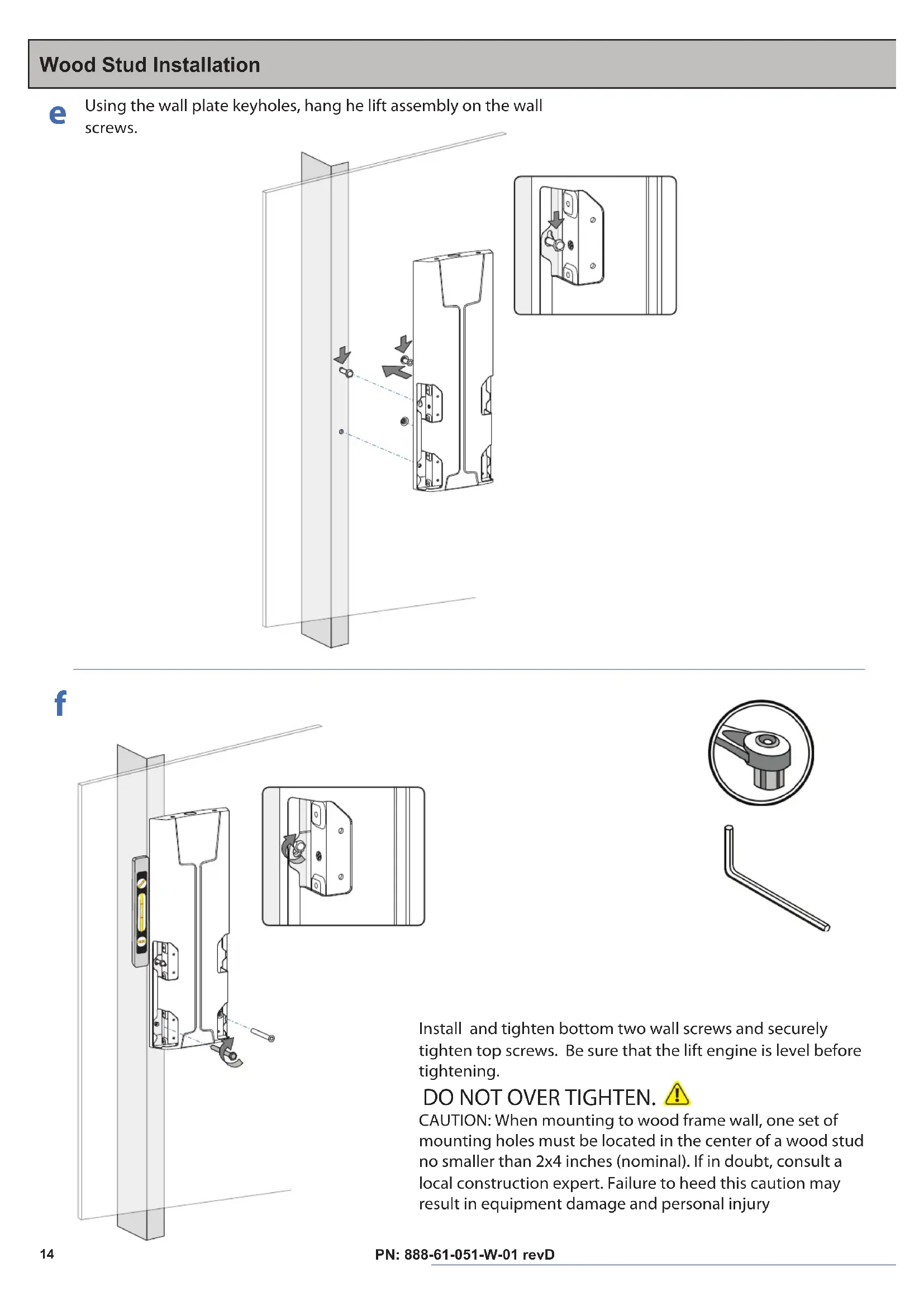
Technical illustration of a mechanical component with a circular inset showing a pin-like feature (no text or symbols)Wood Stud Installation

Using the wall plate keyholes, hang he lift assembly on the wall screws.
natural_image
Technical line drawing of a mechanical bracket assembly with mounting holes and internal components, showing alignment and adjustment arrows (no text or symbols)f
text_image
In ti ti D C m n lo re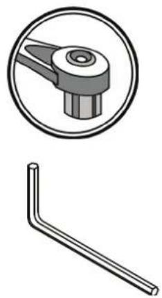
natural_image
Technical illustration of a mechanical component with a circular inset showing a pin-like feature and a separate L-shaped bracket (no text or symbols)Install and tighten bottom two wall screws and securely tighten top screws. Be sure that the lift engine is level before tightening.
DO NOT OVER TIGHTEN.
CAUTION: When mounting to wood frame wall, one set of mounting holes must be located in the center of a wood stud no smaller than 2x4 inches (nominal). If in doubt, consult a local construction expert. Failure to heed this caution may result in equipment damage and personal injury
Determine Mounting Height

CAUTION: Before proceeding with this installation consult your TV product guide for manufacturer recommendations on choosing a mounting location that will ensure optimum TV performance. Location considerations might include: TV height and viewing angle - based on height and distance of seating, room dimensions and size of TV; access to power outlets; cable connections for speakers and other devices; protection from glare and heat, (windows, lamps, fireplace, air ducts) and vibration. Please take into account that this product is being installed in it's highest position. Your TV will only be able to be lowered from it's installed position.
text_image
a Printing Template UPPlace template on wall and mark the mounting holes with a pencil.

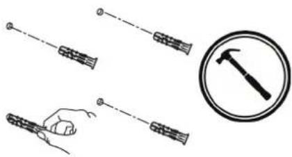
Drill 4 holes.
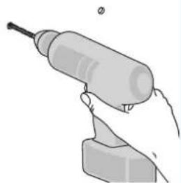
natural_image
Illustration of a hand holding a small electric drill bit with a screwdriver (no text or symbols)
Insert wall anchors into wall.
natural_image
Illustration of four hand tools: a string, a hammer, and a circle (no text or symbols)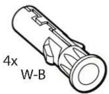
text_image
4x W-B
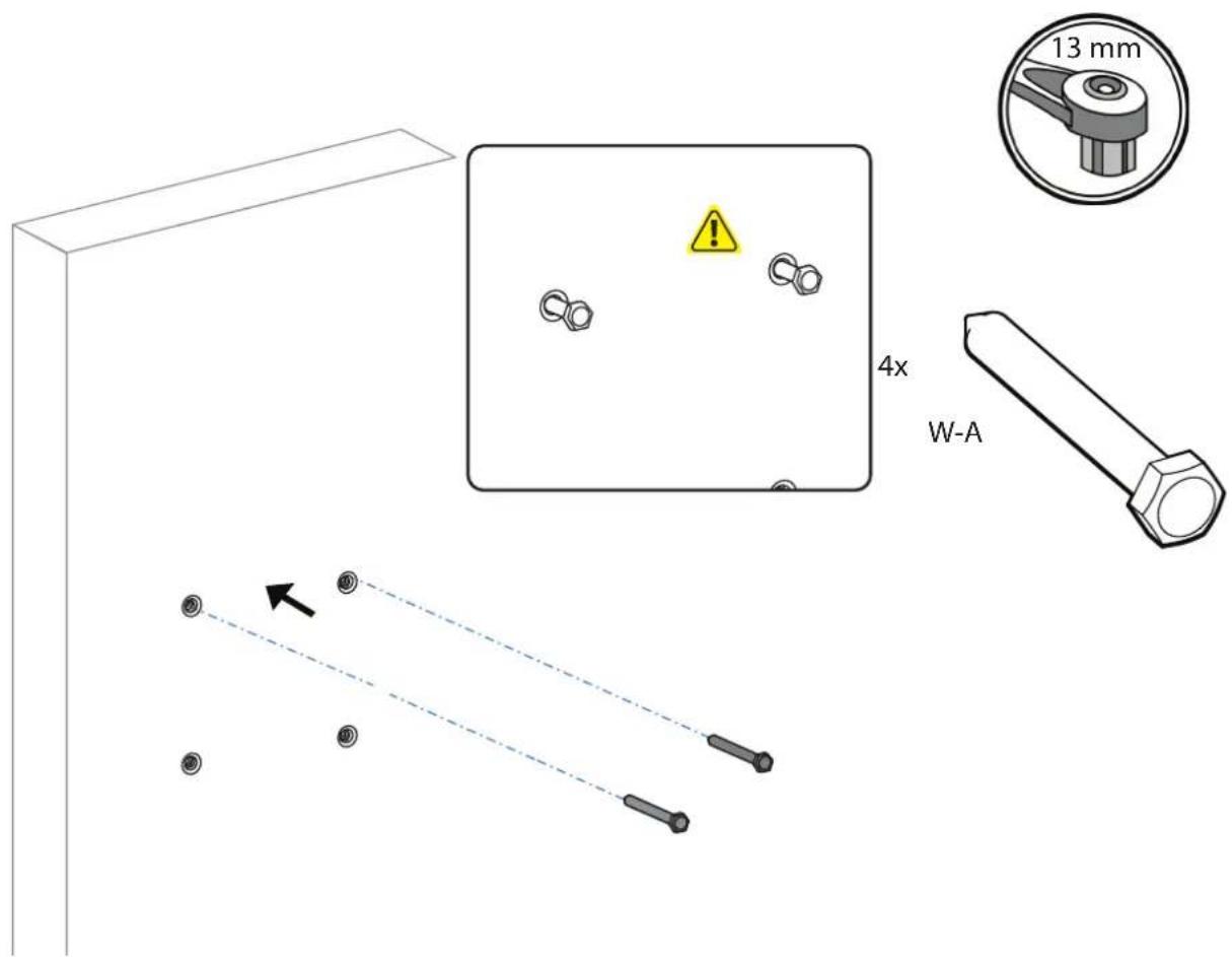
Install top two screws leaving about a 1/2" of room between the head of the screw and the wall.
text_image
13 mm 4x W-ASolid Wall Installation
e
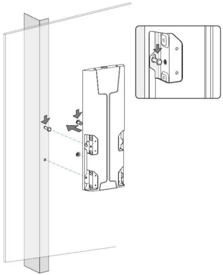
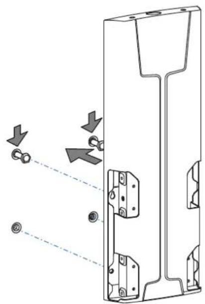
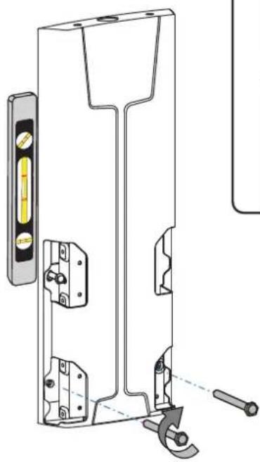
Using the wall plate keyholes, hang he lift assembly on the wall screws.
natural_image
Technical diagram of a mechanical component with arrows indicating assembly or movement (no text or symbols present)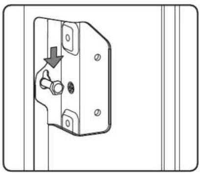
natural_image
Technical line drawing of a door handle with a valve and screw, showing mounting holes and a downward arrow (no text or symbols)f
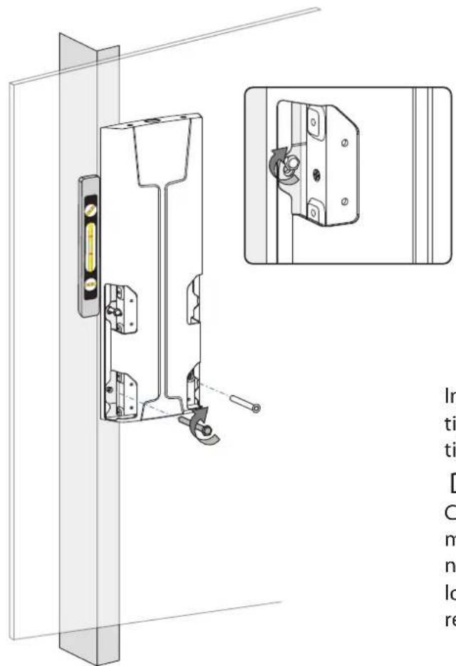
natural_image
Technical line drawing of a door frame with mounting hardware and a tool, no text or symbols present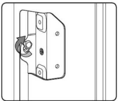
natural_image
Diagram of a door lock mechanism with a rotary knob and mounting holes (no text or symbols)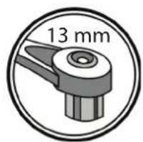
text_image
13 mmInstall and tighten bottom two wall screws and securely tighten top screws. Be sure that the lift engine is level before tightening.
DO NOT OVER TIGHTEN.
CAUTION: When mounting to wood frame wall, one set of mounting holes must be located in the center of a wood stud no smaller than 2x4 inches (nominal). If in doubt, consult a local construction expert. Failure to heed this caution may result in equipment damage and personal injury
text_image
P-B P-A 16x M6 x 8mmHang TV on the Lift Assembly
Hang with monitor attached
natural_image
Symbolic icon of two people sitting at a table with arrows indicating movement or force (no text or symbols)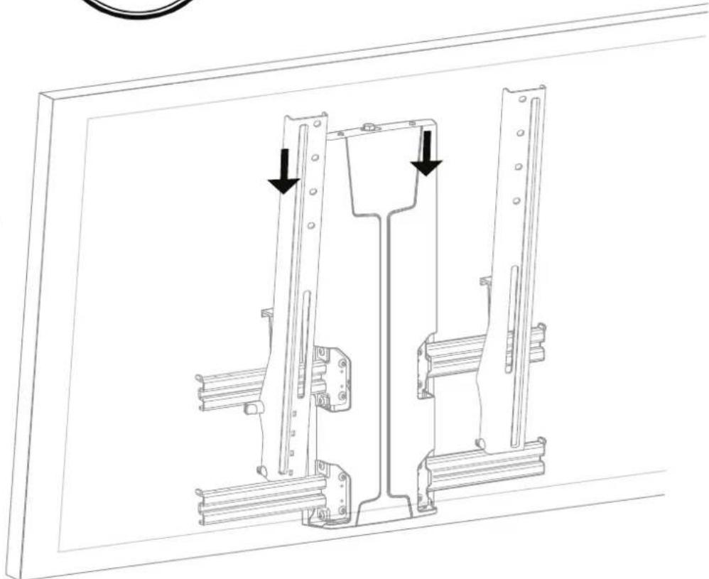
natural_image
Technical line drawing of a mechanical bracket assembly with two mounting holes and directional arrows indicating movement (no text or symbols)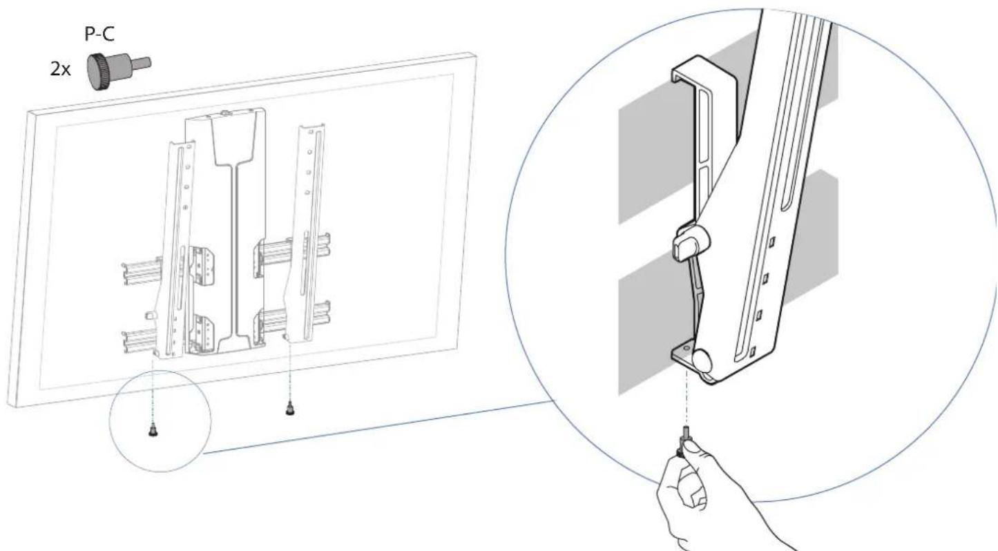
text_image
P-C 2xNOTE: For safe and proper installation be sure to install the locking screw as shown.
Route Cables
Route Cables
Tienda los cables
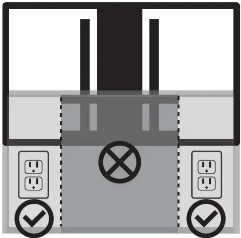
CAUTION: Risk of electrical shock. To ensure safe use of this product, install power outlets or supplies outside of the horizontal rails. Do not route electrical cords within the path of the horizontal rails. Use the below items to appropriately route your power, hdmi, and AV cables. Be aware of pinch points when routing cables. Failure to heed this caution may result in equipment damage or personal injury.
natural_image
Diagram of a device with circuit breakers and switches, no text or symbols present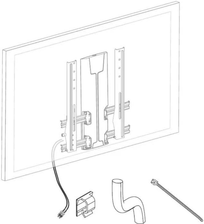
natural_image
Technical line drawing of a wall-mounted electrical panel with attached components including a pipe fitting and a tool (no text or symbols)PN: 888-61-051-W-01 revD

It is important that you adjust this product according to the weight of the mounted equipment as described in the following steps. Any time equipment is added or removed from this product, resulting in a change in the weight of the mounted load, you should repeat these adjustment steps to ensure safe and optimum operation. • Adjustments should move smoothly and easily through the full range of motion and stay where you set it. If adjustments are difficult and do not stay in the desired position, follow the instructions to loosen or tighten the tension to create a smooth, easy adjustment motion. Depending on your product and the adjustment, it may take several turns to notice a difference.
Tilt - Forward and Backward
natural_image
Illustration of a hand holding a tool interacting with a metal bracket (no text or symbols)Page Left Blank Intentionally
This warranty applies to US Residents who purchase from an authorized OmniMount Dealer. OmniMount products are covered against defects in materials and workmanship for 5 years. OmniMount will repair or replace the defective component or product, at its sole discretion. Failure to follow product care instructions from OmniMount will result in void of warranty. To obtain warranty service, contact OmniMount customer service at 800.MOUNT.IT (800.668.6848) or info@omnimount.com. You must supply a copy of your original receipt. If your product must be shipped to OmniMount for inspection, you will be responsible for the shipping charges. Replacement product shipped to you will be returned freight pre-paid. OmniMount disclaims any liability for modifications, improper installations, installations over the specified weight range, or failure to follow care instructions provided by OmniMount. To the maximum extent permitted by law, OmniMount disclaims any other warranties, expressed or implied, including warranties of fitness for a particular purpose and warranties of merchantability. OmniMount will not be liable for any damages arising out of the use of, or inability to use, OmniMount products. OmniMount bears no responsibility for incidental or consequential damages. This includes, but is not limited to, any labor charges for the repair of OmniMount products performed by anyone other than OmniMount. This warranty gives you specific legal rights, and you may also have other rights which vary from state to state. Specifications are subject to change without prior notice.
ESPAÑOL
Notice to customer outside the United States: Please contact the dealer where you purchased this product for details about how to obtain warranty service in your country.
Thank you for purchasing an OmniMount product
REIKIA PAGALBOS? SKAMBINKITE
POTREBUJETE POMOC? PROSÍM, VOLAJTE
НУЖНА ПОМОЩЬ? ЗВОНИТЕ
YARDIM MI LAZIM? LÜTFEN BIZI ARAYIN
TRENGER DU HJELP? RING OSS
您需要帮助吗?请致电
ご質問がある場合は、お電話ください
1-800-MOUNT-IT (USA ONLY)

text_image
OMNI MOUNTErgotron, Inc.
4409 E Baseline Road Ste.130
Phoenix, AZ 85042
1-800-MOUNT-IT (1-800-668-6848)
www.omnimount.com
Ergotron Europe
Beeldschermweg 3
3821 AH Amersfoort
The Netherlands
+31 334545600
www.omnimount.com