
DHH 125012 T - Log splitter Güde - Free user manual and instructions
Find the device manual for free DHH 125012 T Güde in PDF.
| Brand | Güde |
| Model | DHH 125012 T |
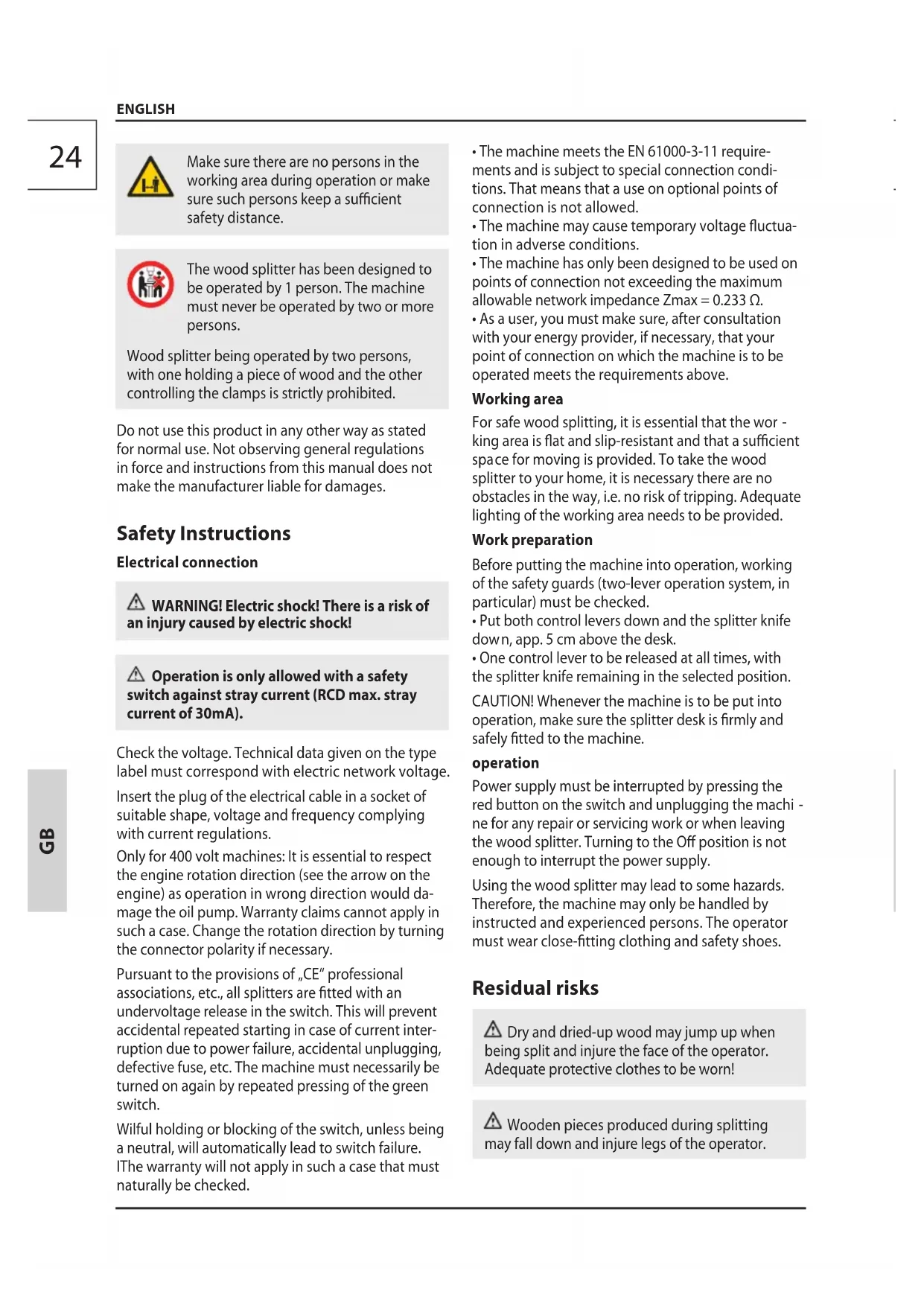
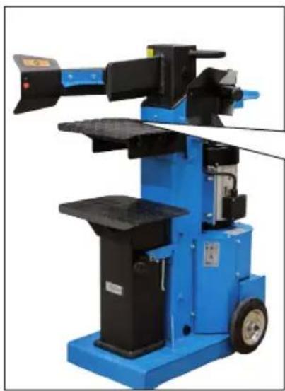
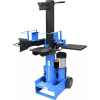
| Product type | Vertical hydraulic wood splitter |
| Power supply | 400 V ~ 50 Hz three-phase |
| Motor power (S6/40%) | 4 kW |
| Maximum splitting pressure | 12 tons |
| Maximum splitting stroke | 550 mm |
| Advance speed | 0.03 m/s |
| Return speed | 0.15 m/s |
| Net weight | 182 kg |
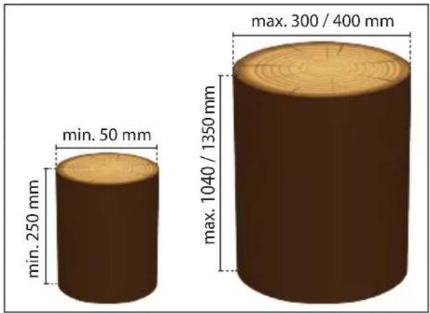
| Maximum log length | 1350 mm |
| Maximum splitting diameter | 400 mm |
| Splitting column section | 120 x 120 mm |
| Table dimensions | 380 x 300 mm |
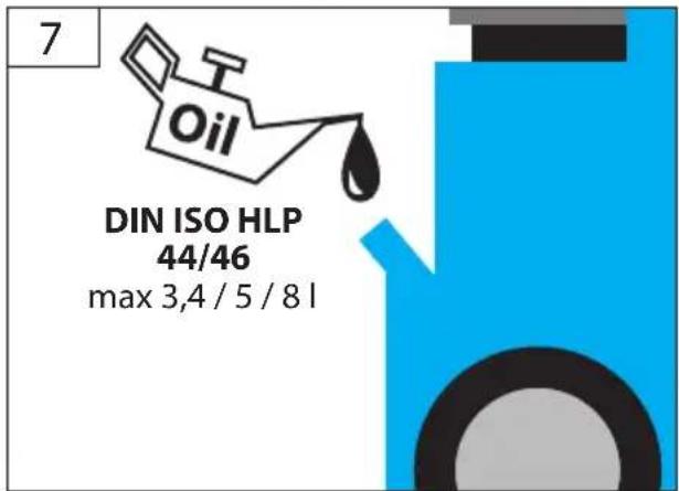
| Hydraulic oil tank capacity | 8 liters (HLP 46) |
| Maximum hydraulic pressure | 250 bar |
| Sound pressure level | 69.9 dB(A) |
| Sound power level | 85.2 dB(A) |
| Vibration emission value | 2.5 m/s² |
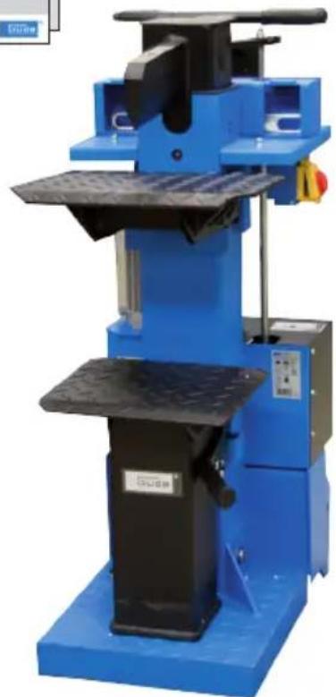
| Control | Double lever for safety (must be operated by both hands) |
| Protection | 30 mA residual current circuit breaker required |
| Usage | One person only, domestic use |
| Warranty | 24 months for the end consumer |
Frequently Asked Questions - DHH 125012 T Güde
User questions about DHH 125012 T Güde
0 question about this device. Answer the ones you know or ask your own.
Ask a new question about this device
Download the instructions for your Log splitter in PDF format for free! Find your manual DHH 125012 T - Güde and take your electronic device back in hand. On this page are published all the documents necessary for the use of your device. DHH 125012 T by Güde.
USER MANUAL DHH 125012 T Güde
natural_image
Blue industrial pallet jack with black handle and metal frame (no visible text or symbols)DHH 1250/12 T
01962
Basic 10T/DTS
020
DHH 1050/8 TC
01963
DHH 1050/10 TP
02004


ENGLISH Please read the instructions carefully before starting the machine.
1
natural_image
Blue industrial machine with black components and a yellow belt, no visible text or symbols4
natural_image
Two black metal mechanical components with blue and red labels (R and L), no visible text or symbols.5
natural_image
Simple line drawing of a pair of tools or tools with circular and triangular elements above two parallel bars (no text or symbols)2
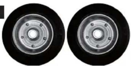
natural_image
Two identical circular mechanical components with central holes and concentric rings (no text or symbols visible)6
natural_image
Pure diagram of a stylized sword or dagger with no text, numbers, or symbols
natural_image
Simple line drawing of a pair of circular shapes and a wavy line on a gray background (no text or symbols)7
| DE | Montage | SI | Montaža |
| GB | Assembly | HR | Montaža |
| FR | Montage | BG | Монтаж |
| IT | Montaggio | RO | Montaj |
| NL | Montage | BA | Montaža |
| CZ | Montáž | ||
| SK | Montáž | ||
| HU | Szerelés |
1
2-4
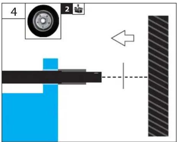
| DE | Inbetriebnahme | SI | Uvedba v pogon |
| GB | Starting-up the machine | HR | Puštanje u rad |
| FR | mise en service | BG | Пускане в действие |
| IT | Messa in funzione | RO | Punerea în funcțiune |
| NL | Inbedrijfstelling | BA | Puštanje u rad |
| CZ | Uvedení do provozu | ||
| SK | Uvedenie do prevádzky | ||
| HU | Üzembe helyezés |
2
5-10
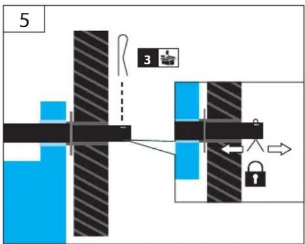
| DE | Betrieb | SI | Delovanje |
| GB | Operation | HR | Rad |
| FR | Fonctionnement | BG | Páboṭa |
| IT | Esercizio | RO | Functionare |
| NL | Gebruik | BA | Rad |
| CZ | Provoz | ||
| SK | Prevádzka | ||
| HU | Üzemeltetés |
3
11-15
| DE | Reinigung / Wartung | SI | Čiščenje / Vzdrževanje |
| GB | Cleaning / Maintenance | HR | Čišćenje / Održavanje |
| FR | Nettoyage / Entretien | BG | Чистене / Поддръжка |
| IT | Pulizia / Manutenzione | RO | Curățare / Întreținere |
| NL | Schoonmaken / Onderhoud | BA | Čišćenje / Održavanje |
| CZ | Čištění / Údržba | ||
| SK | Čistenie / Údrzba | ||
| HU | Tisztítás / Karbantartás |
4
16
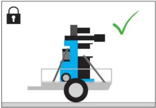
| DE | Transport / Lagerung | SI | Transport / Shranjevanje |
| GB | transport / storage | HR | Prijevoz / Uskladištenje |
| FR | Transport / Stockage | BG | Транспортиране / Съхранение |
| IT | Trasporto / Stoccaggio | RO | Transport / Depozitare |
| NL | Transport / Bewaring | BA | Prevoz / Uskladištenje |
| CZ | Přeprava / Uložení | ||
| SK | Transport / Uloženie | ||
| HU | Szállítás / Tárolás |
5
17
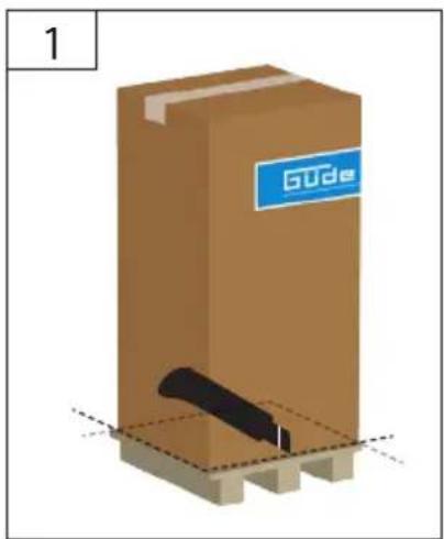
| 1 | DE Montage | SI Montaža |
| GB Assembly | HR Montaža | |
| FR Montage | BG Монтаж | |
| IT Montaggio | RO Montaj | |
| NL Montage | BA Montaža | |
| CZ Montáž | ||
| SK Montáž | ||
| HU Szerelés |


natural_image
3D illustration of a brown cardboard box with a black tool inserted, placed on a wooden base (no text or symbols)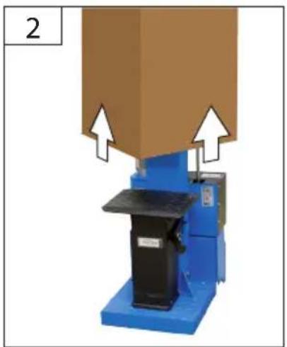
natural_image
Industrial machine with blue base and black component, no visible text or symbols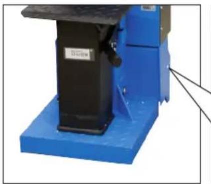
natural_image
Industrial machine component with blue base and black top, no visible text or symbols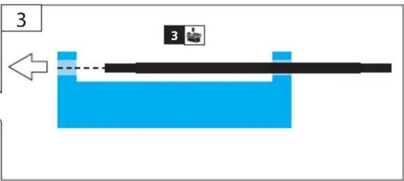
DE Montage
SI Montaža
GB Assembly
HR Montaža
FR Montage
BG Монтаж
IT Montaggio
RO Montaj
NL Montage
BA Montaža
CZ Montáž
SK Montáž
HU Szerelés

6
natural_image
Two identical mechanical components with blue and red components, no visible text or symbols
natural_image
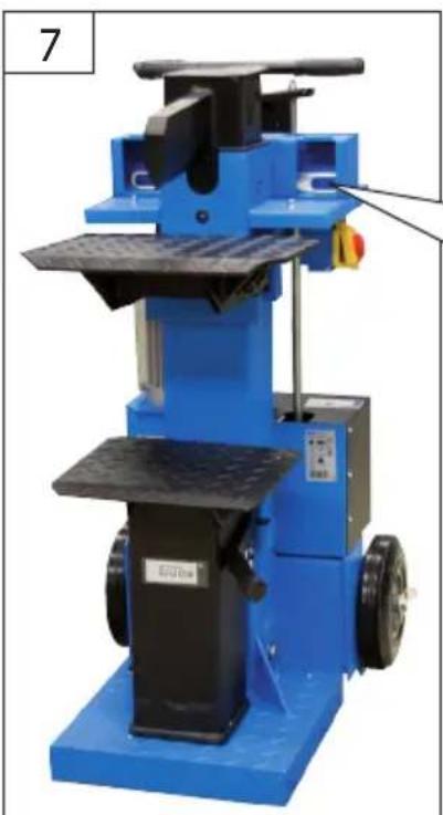
Blue industrial machine with mechanical components and a labeled part (7), no visible text or symbols on the device itself.5


natural_image
Pure mechanical diagram showing a lever mechanism with no text or symbols| 1 | DE | Montage | SI | Montaža |
| GB | Assembly | HR | Montaža | |
| FR | Montage | BG | Монтаж | |
| IT | Montaggio | RO | Montaj | |
| NL | Montage | BA | Montaža | |
| CZ | Montáž | |||
| SK | Montáž | |||
| HU | Szerelés |

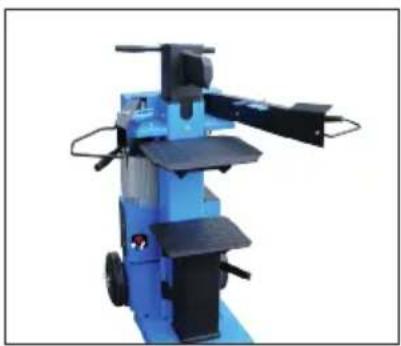
natural_image
Blue industrial machine with mechanical arms and wheels (no visible text or symbols)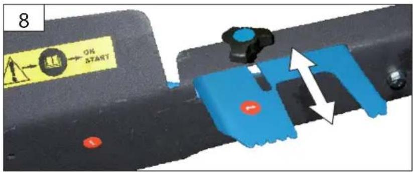
natural_image
Diagram of a mechanical or electrical setup with two hands operating a central circular component, no visible text or symbols.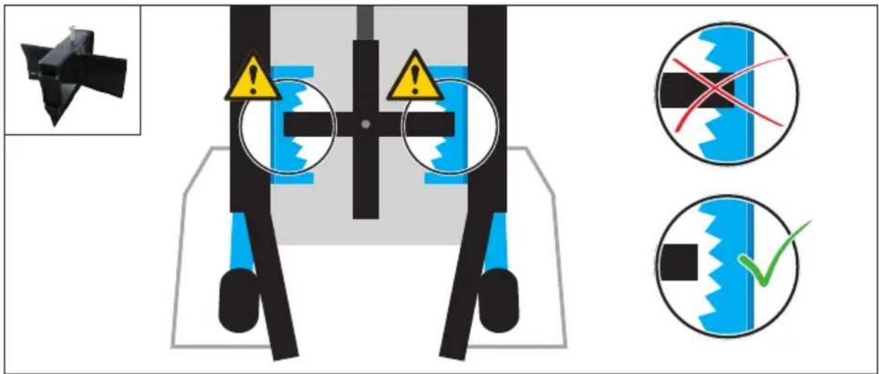
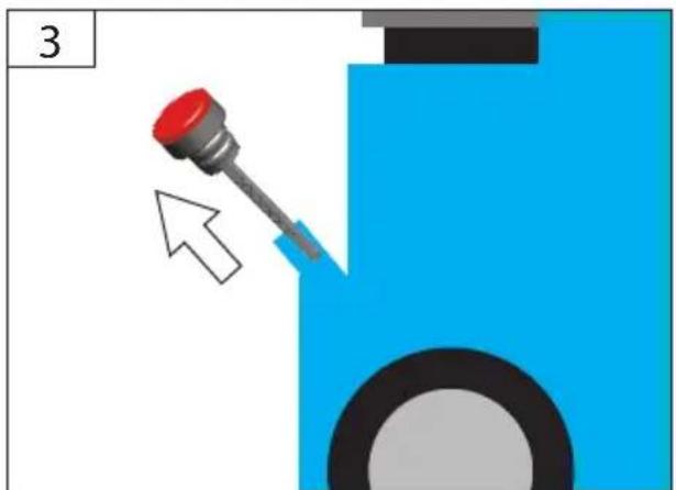
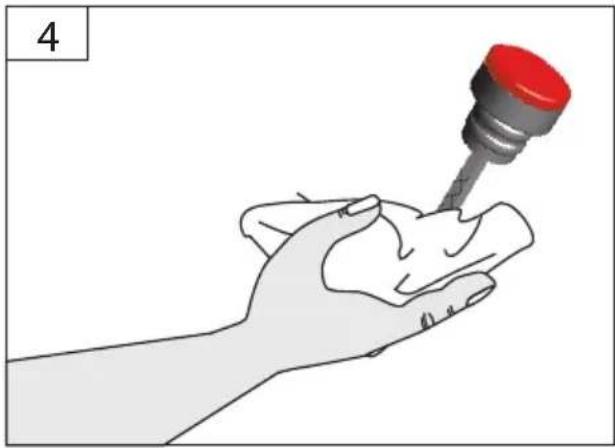
DE Ölstand kontrollieren
GB Oil level inspection
natural_image
Close-up of a blue industrial machine with a circular annotation highlighting a red component (no visible text or symbols)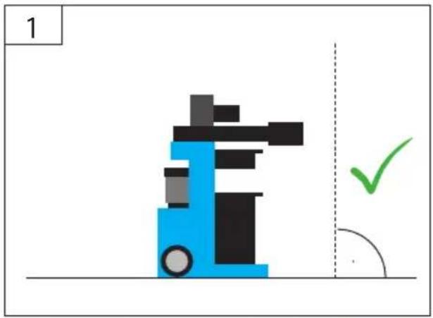
natural_image
Illustration of a blue forklift with black handle and green checkmark indicating alignment (no text or symbols)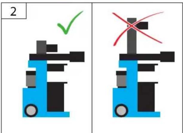
natural_image
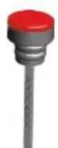
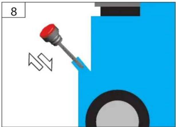
Diagram showing a red-capped screwdriver inserted into a blue container with a circular base, no text or symbols present| 2 | DE Ölstand kontrollierenGB Oil level inspectionFR Contrôle du niveau d'huileIT Controllo livello d'olioNL Oliepeil controlerenCZ Kontrola stavu olejeSK Kontrola stavu olejaHU Olajszint ellenőrzése | SI Kontrola stanja oljaHR Kontrola razine uljaBG Контрол на състоянието на маслотоRO Verificarea stării uleiuluiBA Kontrola nivoa ulja |

natural_image
Illustration of a hand holding a small object with a red cap, no text or symbols present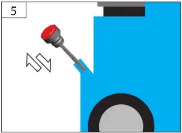
natural_image
Illustration of a screwdriver pressing down on a blue mechanical component with motion arrows (no text or symbols)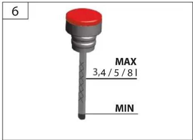
natural_image
Illustration of a mechanical component with a red knob and arrow, no visible text or symbols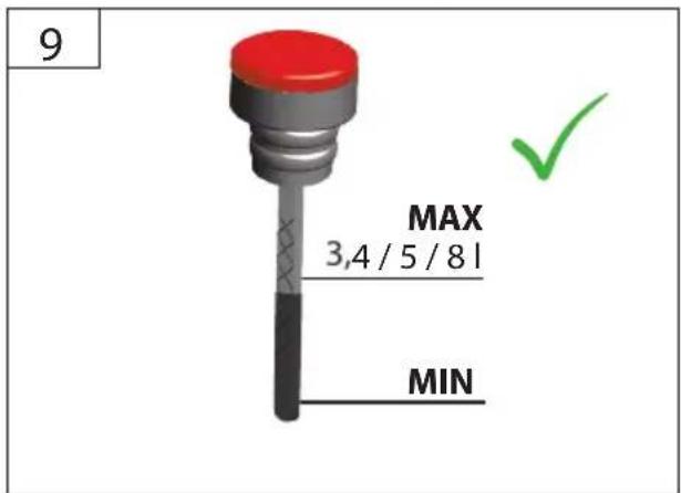
GB Gap length setting
natural_image
Abstract 3D mechanical assembly diagram with colored blocks and directional arrows (no text or symbols)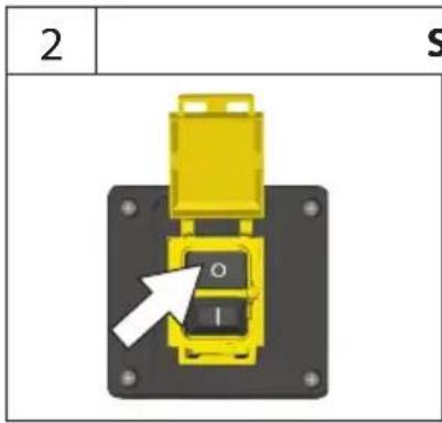

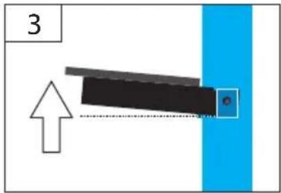
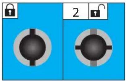
DE Zwischentisch / Schwenktisch
GB Intermediate table / Turntable
FR Table intermédiaire / Table orientable
IT Tavolo intermedio / Tavolo rotante
NL Tussentafel / Zwenktafel
CZ Mezilehlý stůl / Otočný stůl
SK Medzil'ahlý stôl / Otočný stôl
HU Köztes asztal / Forgóasztal
SI Vmesna miza / Vrtljiva miza
HR Međustol / Obrtni tol
BG Междинна маса / Въртяща се маса
RO Masă intermediară / Masă rotativă
BA Međustol / Obrtni stol

DHH 1250/12 T
Basic 10T/DTS
natural_image
Blue industrial machine with mechanical components and a circular base (no visible text or symbols)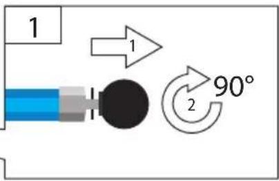
natural_image
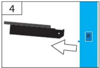
Diagram showing a mechanical component with an arrow pointing to a blue vertical panel (no text or symbols)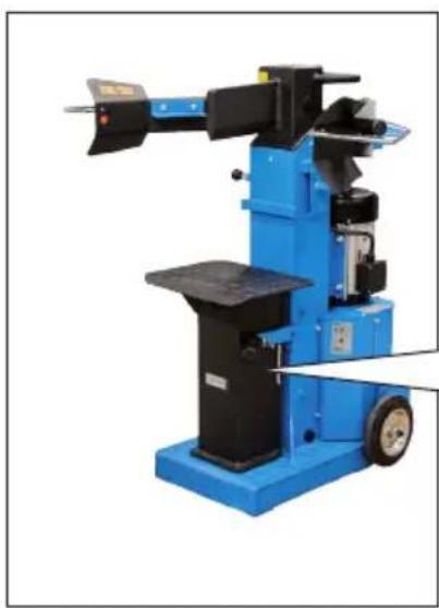
natural_image
Blue industrial machine with mechanical components and a tool, no visible text or symbols
natural_image
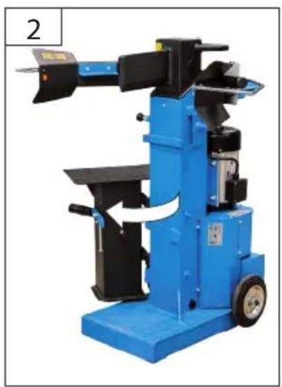
Blue industrial machine with mechanical arms and a directional arrow indicating rotation (no visible text or symbols)DE Zwischentisch
GB Intermediate table
| DE | Betrieb | SI | Delovanje |
| GB | Operation | HR | Rad |
| FR | Fonctionnement | BG | Pabota |
| IT | Esercizio | RO | Functionare |
| NL | Gebruik | BA | Rad |
| CZ | Provoz | ||
| SK | Prevádzka | ||
| HU | Üzemeltetés |


natural_image
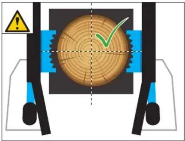
Two 3D diagrams showing a wooden log with a green checkmark and a cross-section of the same structure (no text or symbols)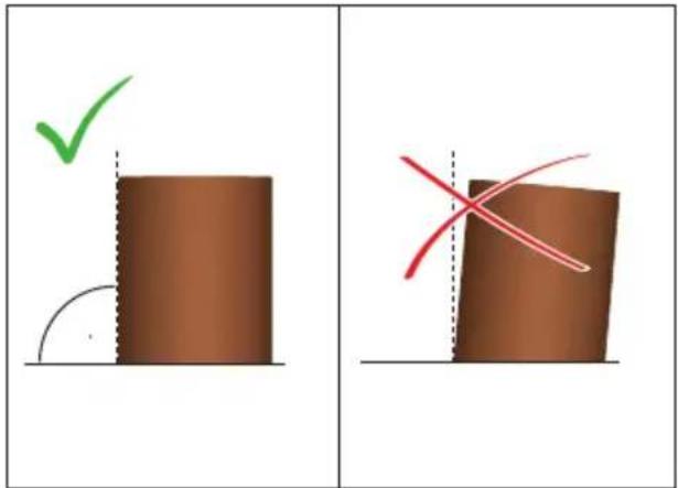
natural_image
Pixelated illustration of a blue forklift with black handle and green checkmark indicating alignment (no text or symbols)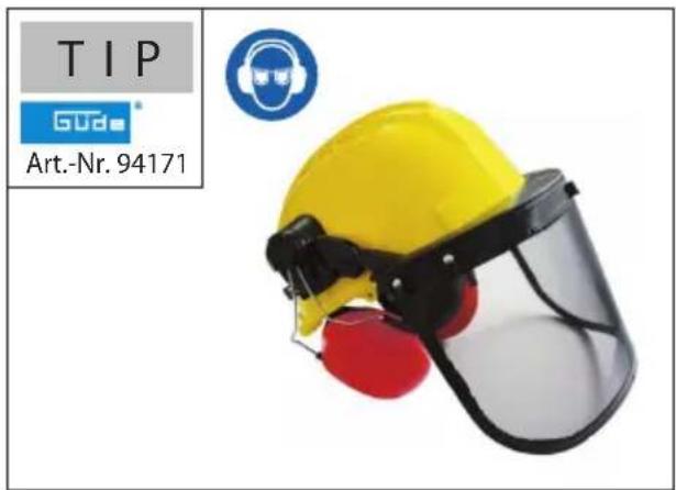
GB Operation - START
natural_image
Illustration of a blue forklift with a green checkmark indicating inspection or approval (no text or symbols present)STOP

natural_image
Blue and black industrial machine with red X-shaped warning symbol (no text or labels)400 V

180^
natural_image
Simple diagram of a circular object with internal symbols and curved arrows, no readable text or labelsSTART
natural_image
Mechanical assembly diagram showing a central shaft with two arms and a blue base, no text or symbols present.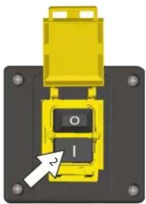
natural_image
Close-up of a yellow mechanical component with a black base and circular button, no visible text or symbols


1min
natural_image
Diagram of a robotic arm with blue base and control points, no text or symbols present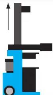
natural_image
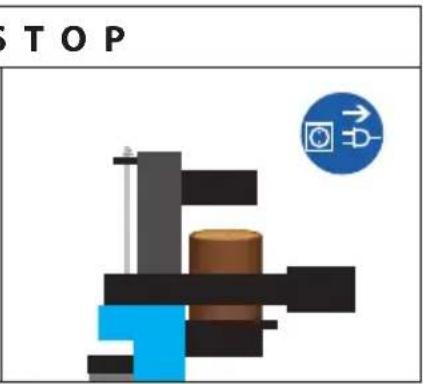
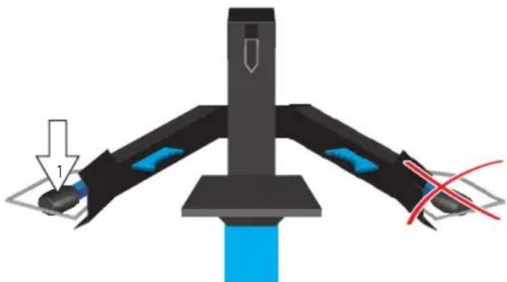
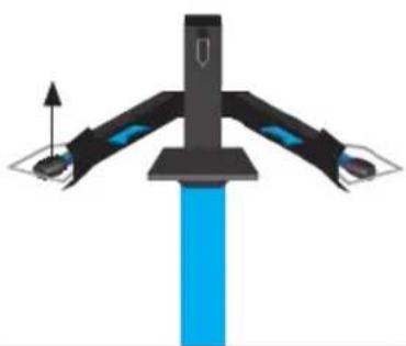
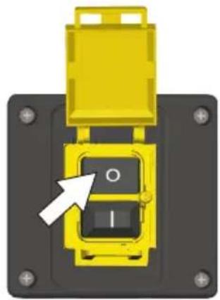
Illustration of a blue and black mechanical device with an upward arrow, no text or symbols present.DE Betrieb - STOP
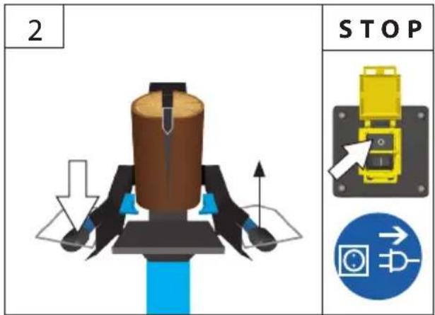
GB Operation - STOP


STOP 1
natural_image
Close-up of a yellow mechanical component with a black square button and arrow pointing to it (no text or symbols visible)STOP 2
natural_image
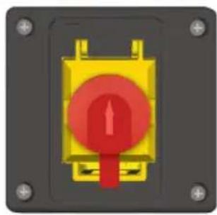
Close-up of a yellow and red electronic component with mounting holes (no text or symbols visible)1
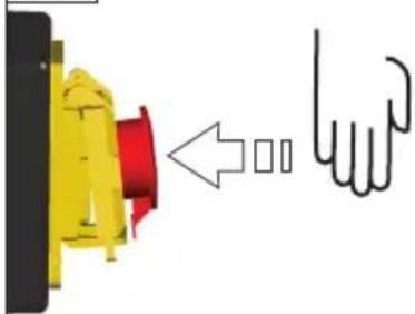
natural_image
Diagram showing a yellow component with red internal structure being pushed by a hand gesture (no text or symbols)2
natural_image
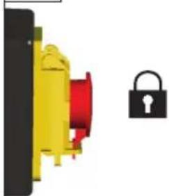
Close-up of a yellow and red electrical component next to a black padlock (no text or symbols visible)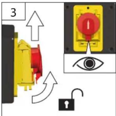
 | DE | Betrieb | SI | Delovanje |
| GB | Operation | HR | Rad | |
| FR | Fonctionnement | BG | Pábota | |
| IT | Esercizio | RO | Functionare | |
| NL | Gebruik | BA | Rad | |
| CZ | Provoz | |||
| SK | Prevádzka | |||
| HU | Üzemeltetés |


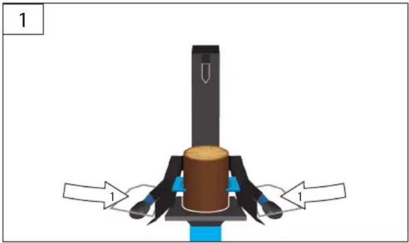
natural_image
Mechanical assembly diagram showing a cylindrical component mounted on a base with two labeled parts (no text or symbols present)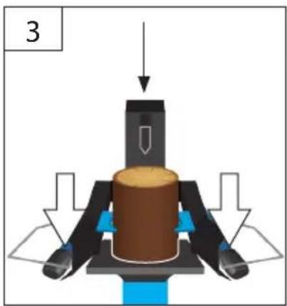
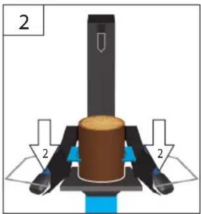
natural_image
Mechanical assembly diagram showing a cylindrical component with directional arrows and a labeled part '3' (no text or symbols on the diagram itself)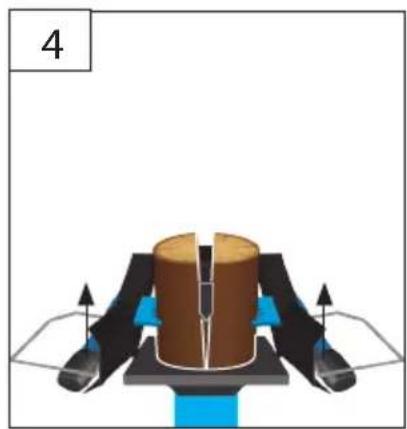
natural_image
Diagram of a mechanical assembly with a central cylindrical component and surrounding components (no text or symbols)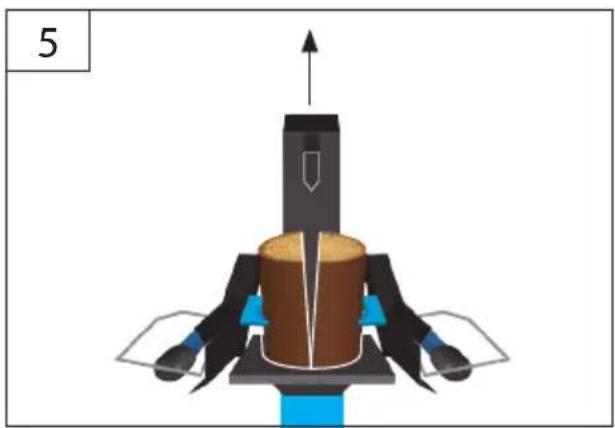
natural_image
3D mechanical assembly diagram showing a piston-like component with arrows indicating upward motion (no text or symbols)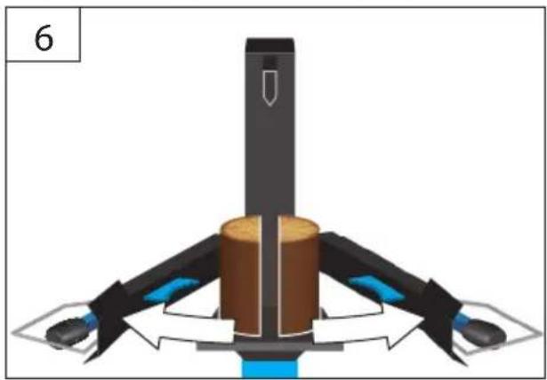
natural_image
Diagram of a mechanical device with four arms and central shaft, no visible text or symbols


natural_image
3D diagram of a mechanical device with labeled components and warning symbol (no readable text or labels)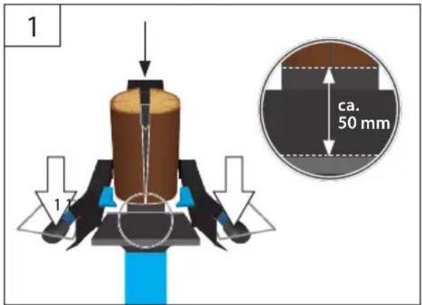
natural_image
Diagram of a mechanical assembly with cross-shaped components and red tool paths (no text or symbols)| 4 | DE Reinigung / Wartung | SI Čiščenje / Vzdrževanje |
| GB Cleaning / Maintenance | HR Čiščenje / Održavanje | |
| FR Nettoyage / Entretien | BG Чистене / Поддръжка | |
| IT Pulizia / Manutenzione | RO Curățare / Întreținere | |
| NL Schoonmaken / Onderhoud | BA Čiščenje / Održavanje | |
| CZ Čištění / Údržba | ||
| SK Čistenie / Údrzba | ||
| HU Tisztítás / Karbantartás |

GB transport / storage
FR Transport / Stockage
NL Transport / Bewaring
natural_image
Silhouette of a person pushing a blue forklift with an arrow indicating direction (no text or symbols)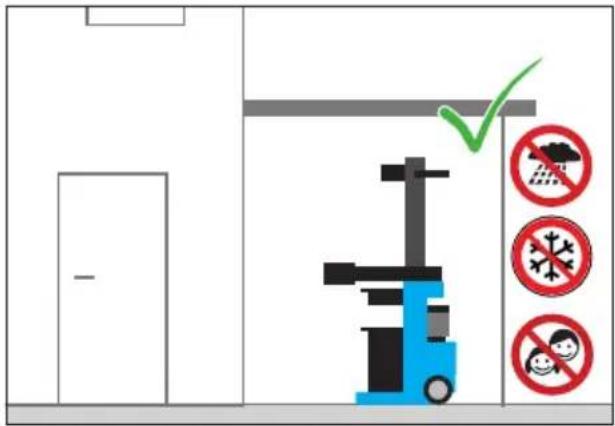
natural_image
Illustration of a blue forklift with a green checkmark indicating inspection or status (no text or symbols)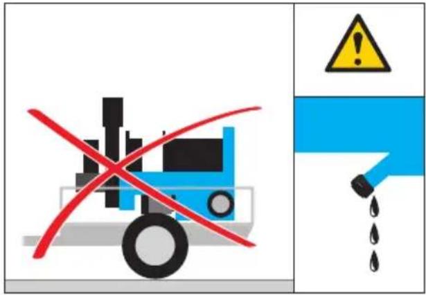
Technische Daten
Hydrauliktank (HLP 46)....3,41....51....81....81
max. Hydralikdruck....210 bar ....210 bar....210 bar....250 bar
Motor output, S6/40%....3,5 kW....3 kW....4,0 kW....4 kW

Engine speed....1400 min ^-1 ....2820 min ^-1 ....1400 min ^-1 ....1440 min ^-1
Max. splitting pressure....8 t....10 t....10 t....12 t

Max. splitting uplift....490 mm....490 mm....510 mm....550 mm

Forward speed....0,04 - 0,05 m/s....0,03 - 0,04 m/s....0,03 m/s....0,03 m/s
Reverse speed ....0,10 - 0,12 m/s ....0,16 m/s ....0,15 m/s ....0,15 m/s
Weight....108 kg....132 kg....177 kg....182 kg
max. Split material lengths....1040 mm....1050 mm....1350 mm....1350 mm
Max. splitting diameter....300 mm....400mm....400mm....400 mm
Splitting post....100 x 100 mm....120 x 120 mm....120 x 120 mm....120 x 120 mm
Table size....300 x 310 mm....380 x 300 mm....380 x 300 mm....380 x 300mm
Hydraulics tank (HLP 46)....3,41....51....81....81
Max. hydraulic pressure....210 bar ....210 bar ....210 bar ....250 bar
Noise and Vibration Information

Sound pressure level L_PA^1) .....69,9 dB (A) .....69,9 dB (A) .....69,9 dB (A) .....69,9 dB (A)
nd power level L _WA^1) 85,2 dB (A) 85,2 dB (A) 85,2 dB (A) 85,2 dB (A)
Vibration emission value a_h .....2,5 m/s ^2 .....2,5 m/s ^2 .....2,5 m/s ^2 .....2,5 m/s ^2
^1) Uncertainty K = 3 db (A)
WARNING The vibration emission level will vary because of the ways in which a power tool can be used and may increase above the level given in this information sheet.
The vibration emission level may be used to compare one tool with another.
It may be used for a preliminary assessment of exposure.
An accurate estimate of the vibratory load should also take into account the times when the tool is shut down or when it is running but not actually in use. This may significantly reduce the vibratory load over the total working period.
Identify additional safety measures to protect the operator from the effects of vibration such as: maintain the tool and the accessories, keep the hands warm, organisation of work patterns.


Read and understand the operating instructions before using the appliance. Abide by all
the safety measures stated in the service manual. Act responsibly toward third parties.
In case of any doubts about connection and operation refer please to our customer center
Specified Conditions Of Use
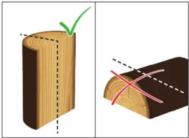
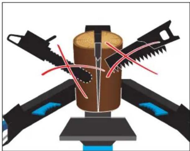
The wood splitter has only been designed to split wood in the fibre direction. Respecting technical data and safety precautions.
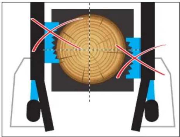
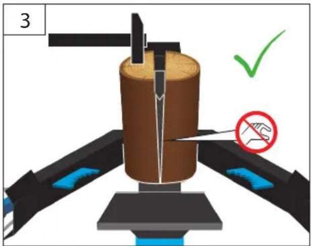
When splitting, it is essential to make sure the split wood only contacts the checkered sheet of the bottom plate or the checkered sheet of the splitting desk.
It is essential to follow instructions for installation, operation, repairs, etc. to prevent hazards and damage.
Please do not forget that this machine, as designed, is not intended for industrial use.

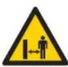
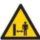
Make sure there are no persons in the working area during operation or make sure such persons keep a sufficient safety distance.

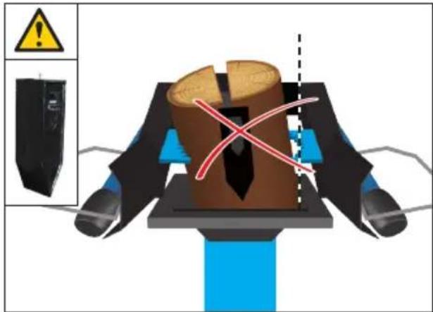
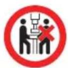
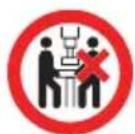
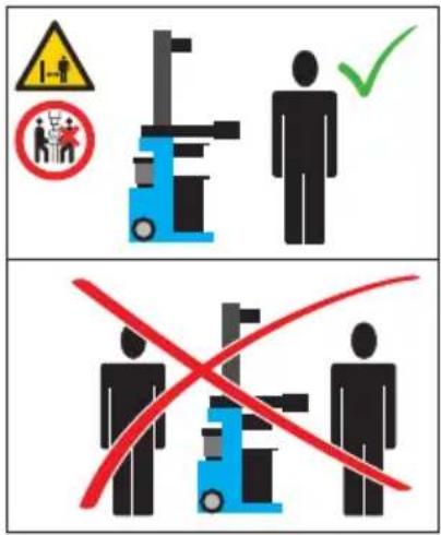
The wood splitter has been designed to be operated by 1 person. The machine must never be operated by two or more persons.
Wood splitter being operated by two persons, with one holding a piece of wood and the other controlling the clamps is strictly prohibited.
Do not use this product in any other way as stated for normal use. Not observing general regulations in force and instructions from this manual does not make the manufacturer liable for damages.
Safety Instructions
Electrical connection

WARNING! Electric shock! There is a risk of injury caused by electric shock!

Operation is only allowed with a safety tch against stray current (RCD max. stray rent of 30mA).
Check the voltage. Technical data given on the type label must correspond with electric network voltage.
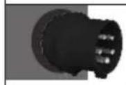
Insert the plug of the electrical cable in a socket of suitable shape, voltage and frequency complying with current regulations.
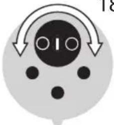
Only for 400 volt machines: It is essential to respect the engine rotation direction (see the arrow on the engine) as operation in wrong direction would damage the oil pump. Warranty claims cannot apply in such a case. Change the rotation direction by turning the connector polarity if necessary.
Pursuant to the provisions of „CE“ professional associations, etc., all splitters are fitted with an undervoltage release in the switch. This will prevent accidental repeated starting in case of current interruption due to power failure, accidental unplugging, defective fuse, etc. The machine must necessarily be turned on again by repeated pressing of the green switch.
Wilful holding or blocking of the switch, unless being a neutral, will automatically lead to switch failure. IThe warranty will not apply in such a case that must naturally be checked.
• The machine meets the EN 61000-3-11 requirements and is subject to special connection conditions. That means that a use on optional points of connection is not allowed.
- The machine may cause temporary voltage fluctuation in adverse conditions.
- The machine has only been designed to be used on points of connection not exceeding the maximum allowable network impedance Z_ = 0.233 .
- As a user, you must make sure, after consultation with your energy provider, if necessary, that your point of connection on which the machine is to be operated meets the requirements above.
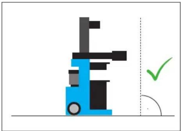
Working area
For safe wood splitting, it is essential that the working area is flat and slip-resistant and that a sufficient space for moving is provided. To take the wood splitter to your home, it is necessary there are no obstacles in the way, i.e. no risk of tripping. Adequate lighting of the working area needs to be provided.
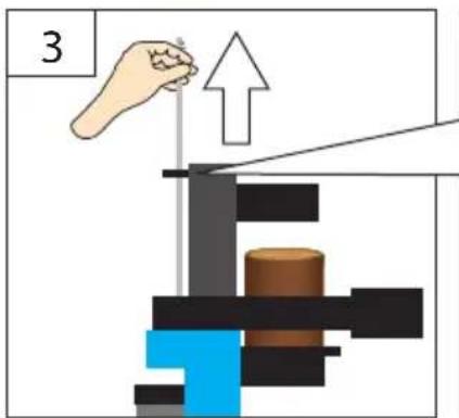
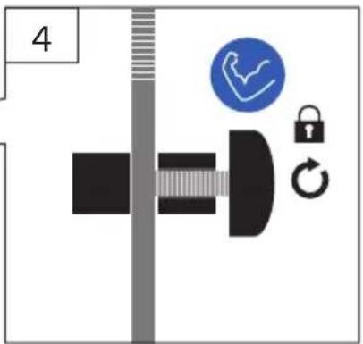
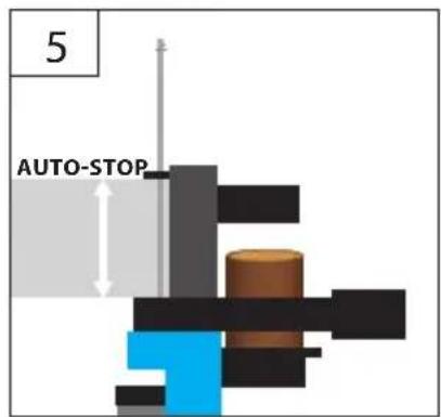
Work preparation
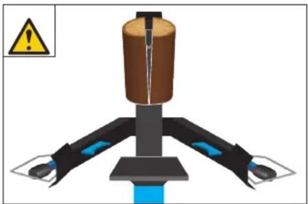
Before putting the machine into operation, working of the safety guards (two-lever operation system, in particular) must be checked.
- Put both control levers down and the splitter knife down, app. 5 cm above the desk.
- One control lever to be released at all times, with the splitter knife remaining in the selected position.
CAUTION! Whenever the machine is to be put into operation, make sure the splitter desk is firmly and safely fitted to the machine.
operation
Power supply must be interrupted by pressing the red button on the switch and unplugging the machine for any repair or servicing work or when leaving the wood splitter. Turning to the Off position is not enough to interrupt the power supply.
Using the wood splitter may lead to some hazards. Therefore, the machine may only be handled by instructed and experienced persons. The operator must wear close-fitting clothing and safety shoes.
Residual risks

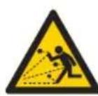
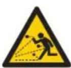
Dry and dried-up wood may jump up when ing split and injure the face of the operator. equate protective clothes to be worn!

Wooden pieces produced during splitting y fall down and injure legs of the operator.
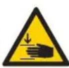
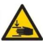
When splitting wood, parts of body may be crushed or separated due to hydraulic knife lowering.
There is a risk of branchy wood getting stuck when being split. Please be advised that wood being separated is under heavy pressure and your fingers may get squeezed in the gap.
Caution!
Pieces of wood cut at the right angle to be split only!
Diagonally cut pieces of wood may slip when cutting!
This may cause personal injury or damage to the splitter knife especially when using the gap extension by wedge!
Requirements for operating staff
The operating staff must carefully read the Operating Instructions before using the appliance.
Qualification: Apart from the detailed instructions by a professional, no special qualification is necessary for appliance using.
Minimum age: Persons over 18 years of age can only work on the appliance. An exception includes youngsters trained in order to reach knowledge under supervision of the trainer during occupational education.
Training: Using the appliance only requires corresponding training by a professional or the Operating Instructions. No special training is necessary.
Emergency procedure
Conduct a first-aid procedure adequate to the injury and summon qualified medical attendance as quickly as possible. Protect the injured person from further harm and calm them down. For the sake of eventual accident, in accordance with DIN 13164, a workplace has to be fitted with a first-aid kit. It is essential to replace any used material in the first-aid kit immediately after it has been used. If you seek help, state the following pieces of information:
- Accident site
- Accident type
- Number of injured persons
- Injury type(s)
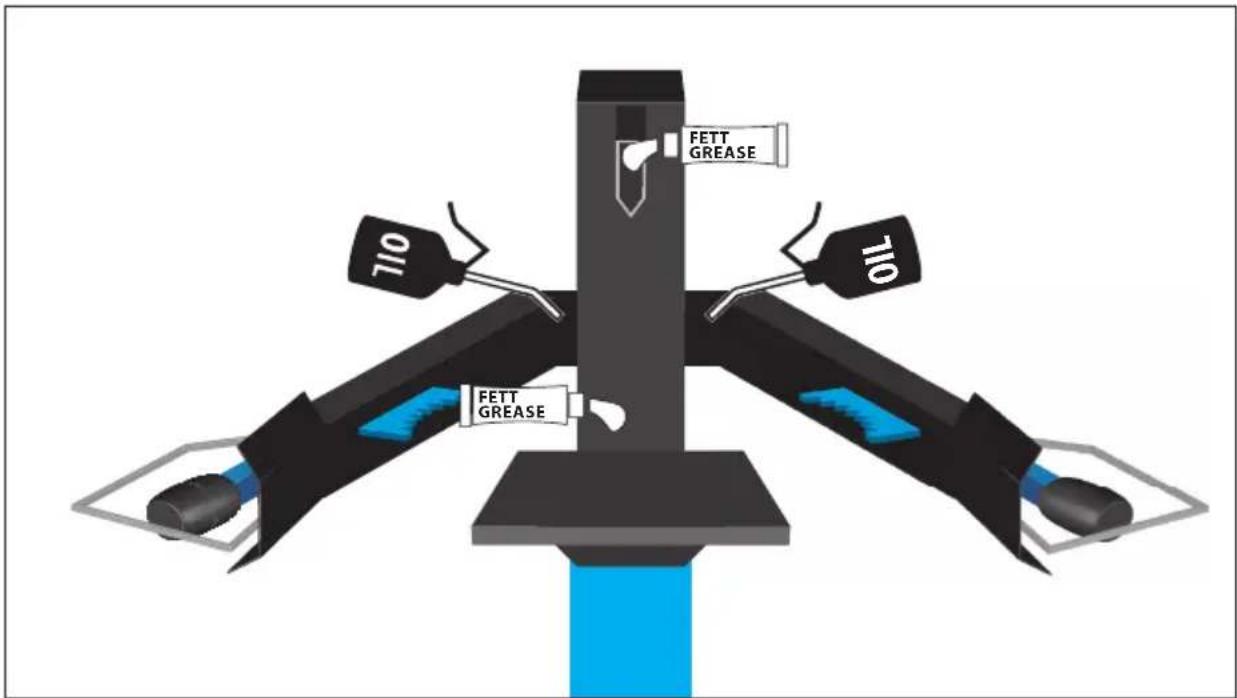
Maintenance
⚠️ Unplug the machine before any work on it.
Carry out a visual inspection before any use to make sure the appliance, especially the cutting tools, fastening parts and the entire cutting unit are not damaged.
The appliance must not be used if damaged or safety equipment is defective. Replace any worn-out and damaged parts.
The hydraulic hoses and connections must be checked if tight enough after app. 4 hours of operation and tightened if necessary.
If the device is defective, the repair has to be made exclusively by the customer service.
Use only original accessories and original spare parts.
Never clean the machine and its components with solvents, flammable or toxic liquids. Us only a damp cloth making.
Only a regularly maintained and treated appliance can serve as a satisfactory aid. Insufficient maintenance and care can lead to unforeseen accidents and injuries.
If necessary, a list of spare parts can be found at www.guede.com.
Symbols

Read the Operating Instructions

Wear eye protective goggles!
Wear ear protectors!

Safety gloves to be used!

Safety shoes to be used

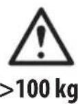
Use of crane
Caution! Moving parts of the machine!

To be operated by 1 person only!

Do not touch in the splitting area!

Protect against humidity. Never expose tool to rain.

WARNING/Caution!

Dangerous voltage

Caution - hot surface!
Danger of burns!

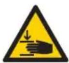
Warning against hand injuries

Keep distance of persons
Observe to keep out of dangerous zone.

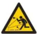
Warning against thrown-off items

Warning against a risk of tripping
Warning against hand injury by the splitter knife

Engine rotation direction

2 people are needed for implementation.
Any damaged or disposed devices must be delivered to appropriate collection centres.

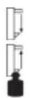
Protect against humidity

This side up
Warranty
Warranty period of 12 months applies to commercial use and 24 months applies to private use and commences on the day of purchase of the device.
Warranty applies exclusively to failures due to defective material or workmanship. An original sale slip with indication of date of sale must be presented in case of claiming for the warranty rights.
VWarranty does not cover unprofessional use such as device overload, violent use, damage caused by third party or foreign materials, failure to comply with operations and assembly manual, and normal wear and tear.
Important information for the customer
Please be sure to know that returning the product in or after the warranty period must be made in the original packaging.
Service
Do you have any technical questions? Any claim? Do you need any spare parts or operating instructions? We will quickly help you and without needles bureaucracy at our web pages at www.guede.com in the Servicing part. Please help us be able to help you. In order to identify your device in case of claim we need the serial No., product No. and year of production. All this data can be found on the type label. Please enter it here for future reference:
Serial No.:
Art. No:
Year of production:
Tel.: +49 (0) 79 04 / 700-360
Fax: +49 (0) 79 04 / 700-51999
E-Mail: support@ts.guede.com
Failure removal
| Failures Causes Removal | ||
| Engine does not start No power in the socket Check the fuse | ||
| Defective electric extension cable Pull the plug out, check it, replace it | ||
| Wrong connecting cable 5-wire connection at 2.5 mm section ^2 cross | ||
| Defective condenser switch Have the machine checked by a professional electrician | ||
| Wrong engine rotation direction Wrong connection Use a screwdriver to turn the phase-changing switch in the power supply | ||
| Splitting knife is not moving Adjust the two-hand control and starting levers | Defective control valve - to be replaced in a service centre only | |
| Splitter has no power | Wrong rotation direction Have the rotation direction changed by a professional | |
| Few hydraulic oil Hydraulic oil to be added | ||
| Trigger is bent; hydraulic piston on the valve is not fully seated | Check all screws on the triggerAdjust the trigger so that the hydraulic piston on the valve is fully seated | |
| Wood has many knobs and the splitting knife is getting stuck | Lubricate the splitting knife | |
| Control arm is bent Put the control arm back to the starting position | ||
| The green supply button does not hold after being pressed | Defective fuse, etc. Check the cable | |
| 2-phase running | ||
| Hydraulic pump is whistling, splitting knife running jerkily | Oil loss, bottom contamination Tighten the screws replace the hose | |
| Few hydraulic oil Hydraulic oil to be added | ||
Potenza del motore, S6/40%....3,5 kW....3 kW....4,0 kW....4 kW
Giri del motore....1400 min ^-1 ....2820 min ^-1 ....1400 min ^-1 ....1440 min ^-1
Max. pressione di spaccatura....8 t....10 t....10 t....12 t
Max. corsa di spaccatura ....490 mm ....490 mm ....510 mm ....550 mm
Velocità avanti....0,04 - 0,05 m/s....0,03 - 0,04 m/s....0,03 m/s....0,03 m/s
Velocità indietro 0,10 - 0,12 m/s 0,16 m/s 0,15 m/s 0,15 m/s
Peso....108 kg....132 kg....177 kg....182 kg
max. Lunghezze del materiale da spaccare .....1040 mm ..... 1050 mm ..... 1350 mm ..... 1350 mm
Max. diametro per spaccatura.... 300 mm....400mm....400mm....400 mm
Colonna di spaccatura....100 x 100 mm....120 x 120 mm....120 x 120 mm....120 x 120 mm
WAARSCHUWING/Opgelet!

Attentie, elektrische stroom

Zmogljivost motorja, S6/40%....3,5 kW....3 kW....4,0 kW....4 kW
Vrtljaji motorja....1400 min ^-1 ....2820 min ^-1 ....1400 min ^-1 ....1440 min ^-1
Maks. tlak cepljenja....8 t....10 t....10 t....12 t
Maks. dvig cepljenja....490 mm....490 mm....510 mm....550 mm
Hitrost delovanja naprej....0,04 - 0,05 m/s....0,03 - 0,04 m/s....0,03 m/s....0,03 m/s
Hitrost povratnega delovanja ....0,10 - 0,12 m/s ....0,16 m/s....0,15 m/s....0,15 m/s
Teža....108 kg....132 kg....177 kg....182 kg
max. Dolžina nihalnega materiala .... 1040 mm .... 1050 mm .... 1350 mm .... 1350 mm
Maks. premer cepljenja.... 300 mm....400mm....400mm....400 mm
Višina cepljenja....100 x 100 mm....120 x 120 mm....120 x 120 mm....120 x 120 mm
Velikost mize....300 x 310 mm....380 x 300 mm....380 x 300 mm....380 x 300mm
Rezervoar hidravlike (HLP 46)....3,41....51....81....81
Najvišji hidravlični tlak ....210 bar ....210 bar ....210 bar ....250 bar
Informacije o hrupnosti in vibracijah
Akustični tlak L _PA^1) ......69,9 dB (A)......69,9 dB (A)......69,9 dB (A)......69,9 dB (A)
Akustična zmogljivost L _WA^1) 85,2 dB (A) 85,2 dB (A) 85,2 dB (A) 85,2 dB (A)
Vrednost emisij, nastalih pri vibriranju a_h 2,5 m/s ^2 2,5 m/s ^2 2,5 m/s ^2 2,5 m/s ^2 2,5 m/s ^2
^1) Nihanje K = 3 db (A)
Snaga motora, S6/40%....3,5 kW....3 kW....4,0 kW....4 kW
Obrtaji motora 1400 min

Maks. tlak cijepanja....8 t....10 t....10 t....12 t
Maks. podizaj cijepanja....490 mm....490 mm....510 mm....550 mm

Brzina rada naprijed....0,04 - 0,05 m/s....0,03 - 0,04 m/s....0,03 m/s....0,03 m/s

Brzina povratnog hoda....0,10 - 0,12 m/s....0,16 m/s....0,15 m/s....0,15 m/s
Masa....108 kg....132 kg....177 kg....182 kg
max. Dužine sečenog materijala ....1040 mm ....1050 mm....1350 mm ....1350 mm
Maks. tlak cijepanja .... 300 mm .... 400mm .... 400mm .... 400 mm
Visina cijepanja....100 x 100 mm....120 x 120 mm....120 x 120 mm....120 x 120 mm
Veličina stola....300 x 310 mm....380 x 300 mm....380 x 300 mm....380 x 300mm
Rezerovar za hidraulični sistem (HLP 46)....3,4 l....5 l....8 l....8 l
Maks. hidraulički tlak ....210 bar ....210 bar ....210 bar ....250 bar
EC-DECLARATION OF CONFORMITY
We, hereby declare the conception and construction of the below mentioned appliances correspond - at the type of construction being launched - to appropriate basic safety and hygienic requirements of EC Directives. In case of any change to the appliance not discussed with us the Declaration expires.
DECLARATION CE DE CONFORMITE
PROHLASENI O SHODE EU
2006/95/EC 2004/108/EC
2009/105/EC 1907/2006/EC
2011/65/EC ROHS 2009/142/EC
89/686/EEC (PPE) 1935/2004/EC
□ □
2006/42/EC
Annex IV
Notified Body:
Reg. No.:
2000/14/EC_2005/88/EC
Noise: guaranteed L_WA dB (A)
97/6 8/EC_
Emission No.:

- 01962
- 020
- 01963
- 02004
- DE Ölstand kontrollieren
- DHH 1250/12 T
- Basic 10T/DTS
- Technische Daten
- Noise and Vibration Information
- Specified Conditions Of Use
- Safety Instructions
- Electrical connection
- Working area
- Work preparation
- operation
- Residual risks
- Caution!
- Requirements for operating staff
- Emergency procedure
- Maintenance
- ⚠️ Unplug the machine before any work on it.
- Symbols
- Warranty
- Important information for the customer
- Service
- Informacije o hrupnosti in vibracijah
- EC-DECLARATION OF CONFORMITY
- DECLARATION CE DE CONFORMITE
- PROHLASENI O SHODE EU
Brand : Güde
Model : DHH 125012 T
Category : Log splitter