
RS2W - Smart Home Renkforce - Free user manual and instructions
Find the device manual for free RS2W Renkforce in PDF.
| Product type | Radio measurement display thermostat with temperature control |
| Brand | Renkforce |
| Model | RS2W |
| Dimensions (L x W x H) | 101 x 63 x 17 mm |
| Weight (batteries included) | Approx. 900 g |
| Power supply | 2 AAA/Micro batteries (1.5 V) |
| Battery life | Approx. 1 year |
| Frequency band | 868 MHz |
| Transmission power | 11.85 dBm |
| Radio range | Up to 150 m (free field) |
| Time accuracy | +/- 90 seconds per month |
| Temperature tolerance | +/- 1 °C |
| Voltage tolerance | +/- 1 V |
| Current tolerance | +/- 0.002 A (≤10 W) / +/- 0.5 to 1% (>10 W) |
| Power tolerance | +/- 0.3 W (≤10 W) / +/- 0.5 to 1% (>10 W) |
| Number of controllable sockets | Up to 3 |
| Operating modes | Heating, Cooling, 24h Control, Time windows |
| Display | V, A, W, kWh, temperature, time |
| Operating temperature | 20 °C to +55 °C |
| Permissible humidity | 20% to 90% RH without condensation |
| Package contents | Thermostat, 2 AAA batteries, instruction manual |
| Maintenance | Clean with a dry cloth; do not use abrasive products |
| Safety | Keep out of reach of children; do not expose to moisture or extreme temperatures |
| Repairability | No user-serviceable parts; contact customer service in case of malfunction |
Frequently Asked Questions - RS2W Renkforce
User questions about RS2W Renkforce
0 question about this device. Answer the ones you know or ask your own.
Ask a new question about this device
Download the instructions for your Smart Home in PDF format for free! Find your manual RS2W - Renkforce and take your electronic device back in hand. On this page are published all the documents necessary for the use of your device. RS2W by Renkforce.
USER MANUAL RS2W Renkforce
www.business.conrad.at
Schweiz:
www.conrad.ch
www.biz-conrad.ch
2. Symbol-Erklärung

www.conrad.com/downloads
- Introduction 20
- Explanation of symbols 20
- Intended use 21
- Product description 21
- Scope of delivery 21
- Safety information 22
- Battery/rechargeable battery instructions 23
- Inserting the batteries 24
- Operating elements 25
a) Radio measuring display/thermostat 25
b) Radio measuring switching socket 25
- General notes on operation 26
a) Setting Time and Weekday 26
b) Binding radio measuring display/thermostat to radio measuring switching socket ....27
c) Deleting the binding of a measuring switching socket. 28
d) Selecting the radio measuring switching socket. 28
e) Switching the radio measuring switching socket On or Off 28
f) Reset of the consumption display for a radio measuring switching socket 28
- Programming notes 29
a) Operating modes "Cooling" or "Heating". 29
b) Operating mode "24-Hour Temperature Control" 29
c) Operating mode "Temperature Control in Time Windows" 31
d)Overwriting time windows. 33
e) Delete time window 33
- Setups and mounting hooks 33
Page
- Disposal 34
a) Product 34
b) Batteries/rechargeable batteries 34
14.Declaration of Conformity (DOC) 34
15. Technical data 35
1. Introduction
Dear Customer,
thank you for purchasing this product.
To maintain this status and to ensure safe operation, you as the user must observe these operating instructions!

These operating instructions are part of this product. They contain important notes on commissioning and handling. Also consider this if you pass on the product to any third party. Therefore, retain these operating instructions for reference!
If there are any technical questions, please contact:
International: www.conrad.com/contact
United Kingdom: www.conrad-electronic.co.uk/contact
2. Explanation of symbols

The exclamation mark indicates important notes in these operating instructions that must be strictly observed.
The arrow symbol indicates that special advice and notes on operation are provided.
3. Intended use
The RS2W radio measuring display/thermostat (item no. 1429366) control and measures the power consumption of the connected devices in connection with the RS2W radio measuring switching socket (item no. 1429367) and also displays various measured values for this. The RS2W radio measuring display/thermostat is battery-operated.
No other energy supply must be used. Any other use than that described above will lead to damage to the product and involves other risks, such as short circuit, fire, etc.
4. Product description
The RS2W radio measuring display/thermostat is operated with two batteries of size AAA/Micro and controls up to three RS2W radio measuring switching sockets. Additionally, this device can read various measured values (current, voltage, wattage). These values are determined by the radio measuring switching socket and transmitted to the RS2W radio measuring display/ thermostat by radio. Various automatic programs can be set as well.
In these instructions, the operation both of the RS2W radio measuring display/thermostat and the RS2W radio measuring switching socket. The RS2W radio measuring switching socket (item no. 1429367) is not part of the scope of delivery and must be received separately.
5. Scope of delivery
- Wireless meter display/thermostat
- 2 batteries type AAA/Micro
- Operating instructions
Up-to-date operating instructions
Download the latest operating instructions via the link www.conrad.com/downloads or scan the QR code. Follow the instructions on the website.

6. Safety information

The guarantee/warranty will expire if damage is incurred resulting from noncompliance with the operating instructions! We do not assume any liability for consequential damage! Nor do we assume any liability for damage to property or personal injury caused by improper use or failure to observe the safety information. In such cases the warranty/guarantee is voided.
- The unauthorised conversion and/or modification of the product is not permitted for safety and approval reasons.
- The product is not a toy and does not belong in the hands of children. Position the product so it is out of the reach of children.
- The product may be used in dry, enclosed indoor areas only; it must not get damp or wet!
- The product must not be exposed to extreme temperatures, direct sunlight or strong vibrations. Keep the product away from strong magnetic fields generated by machines, electric motors or loudspeakers.
- Do not operate the device in environments where there are high levels of dust, flammable gases, vapours or solvents. There is a danger of fire and explosion!
- Do not use this product in hospitals or medical institutions. Although the sensor emits only relatively weak radio signals, these may lead to the malfunction of life-supporting systems. The same may also apply to other areas.
- Do not leave the packaging material unattended since this may become a dangerous plaything for children.
- Handle the product with care; it can be damaged by impacts, blows, or accidental falls, even from a low height.
7. Battery/rechargeable battery instructions

- Batteries/rechargeable batteries must be kept out of the reach of children.
- Do not leave batteries/rechargeable batteries lying around; they could be swallowed by children or pets. If swallowed, consult a doctor immediately.
- Replace flat batteries, rechargeable batteries in time, since flat or old batteries/ rechargeable batteries may leak.
- Leaking or damaged batteries/rechargeable batteries that come in contact with the skin can cause chemical burns, therefore use suitable protective gloves.
- Liquids leaking from batteries/rechargeable batteries are very chemically aggressive. Objects or surfaces coming into contact with these liquids may be severely damaged. Therefore, keep batteries/rechargeable batteries in a suitable location.
- Batteries/rechargeable batteries must never be short-circuited, taken apart or thrown into fire. There is a danger of explosion!
- Do not recharge normal, non-rechargeable batteries; there is a risk of explosion!
- Never mix normal batteries with rechargeable batteries.
- Do not mix batteries/rechargeable batteries with different charges (e.g., full batteries with half-discharged batteries).
- Always replace the complete set of batteries/rechargeable batteries.
- Check that the polarity is correct when inserting the batteries/rechargeable batteries (pay attention to plus/+ and minus/-).
It is possible to operate the product with rechargeable batteries. However, the operating time and the display contrast are greatly reduced due to the lower voltage (battery = 1.5V , rechargeable battery = 1.2V ).
We therefore recommend using only high-quality alkaline batteries instead of rechargeable batteries.
8. Inserting the batteries
Open the battery compartment of the measuring display/thermostat by carefully pushing down the tab at the battery compartment lid and lifting off the lid. Now insert the enclosed batteries in the correct polarity. Observe the symbols in the battery compartment for this.
Operation of the radio measuring display/ thermostat with batteries is not recommended because of the lower cell voltage (battery = 1.5V ,rechargeable battery = 1.2V) and the self-discharge of rechargeable batteries.
At battery change, the connection data (binding) with the radio measuring switching sockets, as well as programmed time windows, will be retained. The time will have to be re-programmed, however.
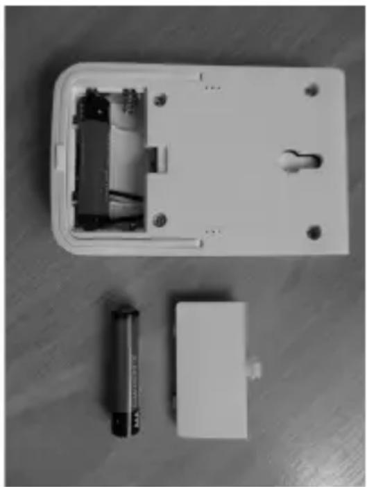
Figure 1
The battery service life is approx. 1 year. A battery change is necessary when the display grows weaker and blurred. Change the batteries now at the latest, since not only legibility of the display, but also possibly the radio range/function may be impaired. We recommend high-quality alkaline batteries as replacement batteries.
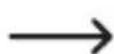
9. Operating elements
a) Radio measuring display/thermostat
1 Display
2+/ON-button
3 FUNC (function) button
4-/OFF-button
5 Measuring aperture for the temperature sensor
b) Radio measuring switching socket
1 Mains connection
2 Programming button/man. activation/deactivation
3 Switching socket
The RS2W radio measuring switching socket (item no. 1429367) is not part of the scope of delivery and must be received separately
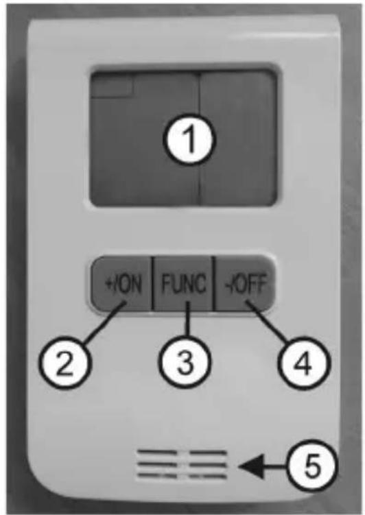
Figure 2
Figure 3
10. General notes on operation
a) Setting Time and Weekday
- Push the button "FUNC" when the radio measuring display/thermostat is ready until you can see "Meter" in the upper left of the display. Now push the button "FUNC" for more than three seconds.
The display for the weekday will now flash. Button + / ON or - / OFF until the right day is set.
-
Now push the button "FUNC" again. The hours display will flash. Push the button + / ON or - / OFF to set the proper number of hours.
-
Now push the button "FUNC" again. The minutes display will flash. Push the button + / ON or - / OFF to set the proper number of minutes.
-
Now push the button "FUNC" again. Setting of weekday and time is ended.
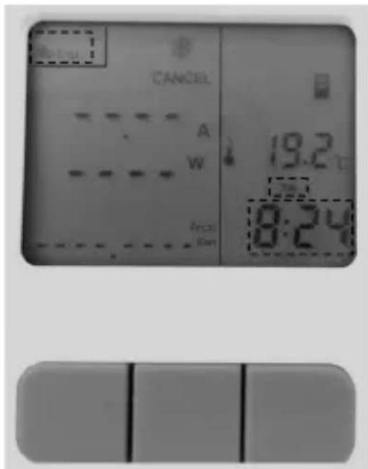
Figure 4

In some countries, the time is switched from winter to summer time in spring and from summer to winter time in autumn. The radio measuring display/thermostat time must be switched to the current time manually every time in this case. Also observe whether possibly set time windows (see chapter 10) are still correct or sensible.
b) Binding radio measuring display/thermostat to radio measuring switching socket
Up to three measuring switching sockets can be bound to one radio measuring display/thermostat.
Push the button "FUNC" when the radio measuring display/thermostat is ready until you can see "Meter" in the upper left of the display. Now push the button + / ON for more than three seconds. The symbol for the switching socket starts to flash.

Figure 5
If no further inputs are made below, the device will switch back to the standard display after approx. 20 seconds.
Now plug a measuring switching socket (item no. 1429367; not enclosed) into a suitable mains socket. The relay in the switching socket clicks and the right function display in the programming button lights up. Now push the programming button at the switching socket for more than three seconds (see figure 3, item 2). Binding has been successfully completed when the symbol of the switching socket no longer flashes in the display. Successful binding is also displayed in that an "optical" connection is displayed between the icon of the switching socket and the chosen channel (arrow - see figure 6).
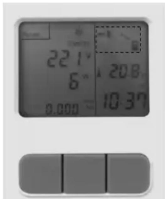
Figure 6
To bind the two devices, they must be in direct proximity to each other. The place where this binding takes place should be as free of radio interference sources as possible. Devices operated on the transmission frequency 866 MHz must be considered particularly strong interference sources (usually, these are radio headphones, radio-controlled weather stations, etc.).
The radio range in the free field is approx. 150 metres. This range is clearly shortened within buildings. However, it is usually still sufficient for safe operation.
The programming button of the measuring switching socket (see figure 3, item 2) can also be used to switch the switching socket manually on and off by pushing it briefly. The switching socket is on when the function display is lit.
c) Deleting the binding of a measuring switching socket
Push the button "FUNC" when the radio measuring display/thermostat is ready until you can see "Meter" in the upper left of the display. Now push the button + / ON for more than three seconds. The symbol for the switching socket starts to flash.
If no further inputs are made below, the device will switch back to the standard display after approx. 20 seconds.
Use the button + / ON to switch off the switching socket (1, 2 or 3 - for example, see figure 7, switching socket 1) that you want to delete. Then push the button + / ON for more than three seconds. Deletion is successfully completed when the icon of the bound switching socket (see figure 6) is no longer displayed.
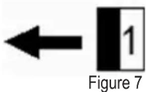
d) Selecting the radio measuring switching socket
Push the button "FUNC" when the radio measuring display/thermostat is ready until you can see "Meter" in the upper left of the display. Use the button + / ON to select the switching socket (1, 2 or 3 - see figure 7) that you want to use.
e) Switching the radio measuring switching socket On or Off
Push the button "FUNC" when the radio measuring display/thermostat is ready until you can see "Meter" in the upper left of the display. Use the button + / ON to select the switching socket (1, 2 or 3 - see figure 7) that you want to use.
Then push the button "FUNC", until the display shows "Manu". The button "+"ON" switches the selected switching socket on manually. The button "-OFF" switches the selected switching socket off manually.
f) Reset of the consumption display for a radio measuring switching socket
Push the button "FUNC" when the radio measuring display/thermostat is ready until you can see "Meter" in the upper left of the display. Use the button + / ON to select the switching socket (1, 2 or 3 - see figure 7) for which you want to reset the consumption display.
Then push the button “-/OFF” for more than three seconds. The reset for the consumption display is successfully completed when the display shows 0.000kW / h in the consumption display.
11. Programming notes
a) Operating modes "Cooling" or "Heating"
The radio measuring display/thermostat can be used to cool or heat rooms - assuming connection of suitable devices to the switching socket. The display will show a sun for heating or a snowflake for cooling.

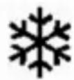
Figure 8
Heating: A heater is connected to a switching socket (item no. 1429367; not enclosed) and is activated when a set temperature is undercut.
Cooling: An air conditioning unit is connected to a switching socket (item no. 1429367, not enclosed) and is activated when a set temperature is exceeded.
Push the button "FUNC" when the radio measuring display/thermostat is ready until you can see "Meter" in the upper left of the display. Use the button + / ON to select the switching socket (1, 2 or 3 - see figure 7) that you want to use.
Select the desired symbol (sun or snowflake - see figure 8) by pushing the button “+/ON” and the button “-/OFF” at the same time for more than three seconds.
b) Operating mode "24-Hour Temperature Control"
The radio measuring display/thermostat can be used to cool or heat rooms - assuming connection of suitable devices to the switching socket. The display will show a sun for heating (heater is connected) or a snowflake for cooling (air conditioning unit is connected).
Push the button "FUNC" when the radio measuring display/thermostat is ready until you can see "Meter" in the upper left of the display. Use the button + / ON to select the switching socket (1, 2 or 3 - see figure 7) that you want to use.
For 24-hour-monitoring, select the desired operating mode (heating or cooling - see figure 8). Then push the button "FUNC" until "Manu" appears in the display. The upper left of the display shows "Setting".
Now push the button "FUNC" for more than three seconds until the temperature display flashes. Then select the desired temperature with the buttons + / ON and - / OFF . Then push the button "FUNC" again. The 24-hour-temperature monitoring is programmed.
The left part of the display shows the displayed values (volt, ampere, watt, consumed energy) of a connected unit. The right part of the display shows the selected connection "Radio measuring display for radio measuring socket" and the current temperature and time.
To activate the 24-hour-temperature monitoring, first push button "FUNC" repeatedly until the left half of the display shows "Meter" and "Cancel". Then push the button "-/OFF", until the display shows "Manu". The radio measuring display/thermostat will now monitor the set temperature. If, for example, the radio measuring switching socket 2 was activated, the symbol will appear as shown in Figure 9.
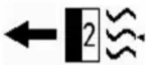
Figure 9
Example:
You have chosen the operating mode "Cooling" and temperature 22^ . An air conditioning unit is connected to the selected switching socket. If the temperature in the room in which the radio measuring display/thermostat is located rises above the set "target temperature" of 22^ for a certain time, the radio measuring display/thermostat will send the signal "activate" to the chosen radio switching socket.
The air conditioning unit will start to work. The left half of the display will now alternate between the mains voltage in Volt (V) and the current required by the connected device in Ampere (A). Additionally, the power of the connected device in Watt (W) is displayed below this. The very bottom of the display shows the total of power used in kW/h.
If the room temperature permanently drops below the "target temperature" (here: 22^ ), the air conditioning unit is switched off again by the radio measuring display/thermostat. To deactivate this 24-hour temperature monitoring, push the button "-/OFF" repeatedly until "Cancel" appears in the display.

If 24-hour temperature monitoring is deactivated again (Cancel), the switching condition that was activate at deactivation will be preserved. Therefore, you must switch off any activated switching sockets manually after deactivation (see chapter 9).
The temperature-controlled activation and deactivation of the switching sockets, as well as updating of the measured values, always happens with a delay.
If several switching sockets are to be controlled by the radio measuring display/thermostat, each switching socket generally can be programmed individually with "Heating" or "Cooling". Since, however, only one room (where the measuring display/thermostat is located) will be used for temperature monitoring, we recommend "concurrent programming" (all heating or all cooling).
Up to three radio measuring switching sockets can be activated for 24-hour temperature control.
The values determined by the switching socket (Volt, Ampere, Watt) are updated in the display of the radio measuring display/thermostat every three minutes.
c) Operating mode "Temperature Control in Time Windows"
The radio measuring display/thermostat can be used to cool or heat rooms - assuming connection of suitable devices to the switching socket. The display will show a sun for heating (heater is connected) or a snowflake for cooling (air conditioning unit is connected). Additionally, up to eight individual time windows can be programmed with a desired "target temperature".
Push the button "FUNC" when the radio measuring display/thermostat is ready until you can see "Meter" in the upper left of the display. Use the button + / ON to select the switching socket (1, 2 or 3 - see figure 7) that you want to use.
For temperature monitoring by time windows, select the desired operating mode (heating or cooling - see figure 8). Then push the button "FUNC" until "Auto" appears in the display and "Setting" is shown at the upper left.
Push the button + / ON or - / OFF to select the desired memory (1 - 8).
Now push the button "FUNC" for more than three seconds until the temperature display flashes. Then select the desired temperature with the buttons + / ON and - / OFF . Then push the button "FUNC" again.
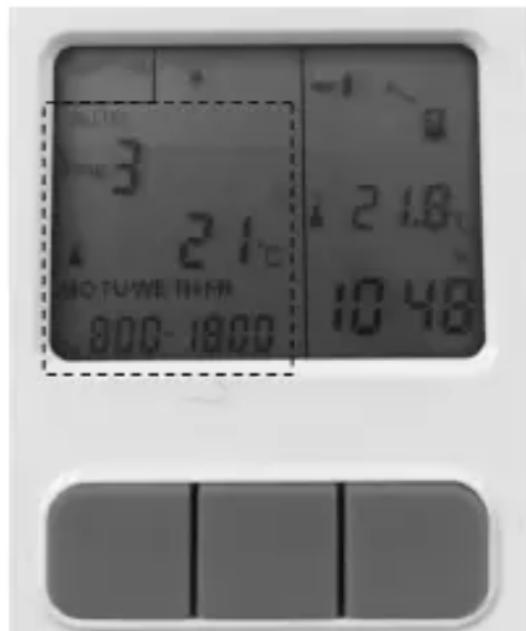
Figure 10
The display for the weekday will now flash. Push the button + / ON or - / OFF to set the desired day. You can also set the day blocks "Monday through Friday" or "Monday through Sunday". Now push the button "FUNC" again. The hours for the start time will now flash in the display. Push the button + / ON or - / OFF to set the proper number of hours.
- Now push the button "FUNC" again. The minutes for the start time will now flash in the display. Push the button + / ON or - / OFF to set the proper number of minutes.
- Now push the button "FUNC" again. The hours for the end time will now flash in the display. Push the button + / ON or - / OFF to set the proper number of hours.
- Now push the button "FUNC" again. The minutes for the end time will now flash in the display. Push the button + / ON or - / OFF to set the proper number of minutes.
- Now push the button "FUNC" again. The left part of the display now shows the "desired temperature". After a few seconds, the electronics switch to the consumption values of a connected device. The right part of the display shows the selected connection "Radio measuring display for radio measuring socket" and the current temperature and time.
- To activate temperature monitoring by programmed time windows, push the button "-/OFF", until the display shows "Auto". The radio measuring display/thermostat will now monitor the set temperature in the programmed time windows.
Example 1:
You have chosen the operating mode "Cooling" and temperature 22^ for the time from 8:00 AM to 12:00 PM. An air conditioning unit is connected to the selected switching socket. When the temperature in the room rises above the set "target temperature" of 22^ for a certain time during the programmed time window, the radio measuring display/thermostat will send the signal "activate" to the chosen radio switching socket.
The air conditioning unit will start to work. The left display will now alternate between the mains voltage in Volt (V) and the current demand of the connected device in Ampere (A). Additionally, the power of the connected device in Watt (W) is displayed below this. The very bottom of the display shows the power used kW/h.
If the room temperature permanently drops below the "target temperature" (here: 22^ ), the air conditioning unit is switched off again. To prematurely deactivate this temperature monitoring by time window, push the button "FUNC" repeatedly until "Cancel" appears in the display.

If an automatic temperature monitoring by time windows is deactivated prematurely (Cancel), the switching condition that was active at deactivation will be preserved. Therefore, you must switch off any activated switching sockets manually after deactivation (see chapter 9).
If the radio measuring switching socket is switched on and the time window ends, the radio measuring switching socket is switched on independently of the room temperature at the expiration of the end time.
If a time window is to be programmed for an entire day, the start and end time must be the same. In this case, you can program additional time windows, but these will be ignored.
At time overlaps between time windows of a radio measuring switching socket, the overlaps are performed as follows. Example 1: Time window 1 is programmed from 0:00 AM to 5:00 AM and time window 2 from 0:00 AM to 4:00 AM. The time window 2 is completely overwritten by time window 1 and will not be applied.
Example 2:
Time window 1 is programmed from 02:00 AM to 5:00 AM and time window 2 from 01:00 AM to 4:00 AM. In this case, the set target temperature from time window 2 is monitored from 1:00 AM to 2:00 AM. The set target temperature from time window 1 is monitored from 02:00 AM to 05:00 AM.
d) Overwriting time windows
A time window can be overwritten at wrong input or if changes are desired. Select the respective time window. Push the button "FUNC" for more than three seconds and change the values as already described in this chapter.
e) Delete time window
A time window can also be deleted completely. Select the desired time window and push the button "-/OFF" for more than two seconds.
12. Setups and mounting hooks
The measuring display/thermostat can be set up on a base (e.g. a table) with the setup integrated into the rear of the housing. Alternatively, you can use a matching screw installed in a wall (screw not enclosed) to suspend the radio measuring display/thermostat on the eyelet integrated in the rear of the housing.
13. Disposal
a) Product
Electronic devices are recyclable and should not be disposed of in household waste. Dispos of the product according to the applicable statutory provisions at the end of its service life.
Remove any inserted batteries/rechargeable batteries and dispose of them separately from the product.
b) Batteries/rechargeable batteries
You as the end user are required by law (Battery Ordinance) to return all used batteries/rechargeable batteries. Disposing of them in the household waste is prohibited.
Batteries/rechargeable batteries that contain hazardous substances are labelled with the adjacent icon to indicate that disposal in domestic waste is forbidden. The descriptions for the respective heavy metals are: Cd=cadmium, Hg=mercury, Pb=lead (the names are indicated on the battery/rechargeable battery e.g. below the rubbish bin symbol shown on the left).
You may return used batteries/rechargeable batteries free of charge at the official collection points of your community, in our stores, or wherever batteries/rechargeable batteries are sold.
You thus fulfil your statutory obligations and contribute to the protection of the environment.
14. Declaration of Conformity (DOC)
We, Conrad Electronic SE, Klaus-Conrad-Straße 1, D-92240 Hirschau, hereby declare that this product conforms to the 2014/53/EU directive.
The full text of the EU conformity declaration is available via the following Internet address:
www.conrad.com/downloads
Select language by clicking a flag symbol and enter the order number of the product in the search field; then you will be able to download the EU declaration of conformity in PDF format.
15. Technical data
Category.Temperature monitoring
Frequency band. 868 MHz
Transmission power. 11,85 dBm
Radio range. 150 m max. (in the open field)
Operating voltage 3 V/DC (2x AAA/Micro battery)
Battery service life approx. 1 year
Accuracy of the clock. + / - 90 seconds per month
Tolerance of the temperature display + / - 1^
Tolerance of the volt display + / - 1V
Tolerance of the current display. + / - 0.002A at = 10W between + / - 0.5% and + / - 1% at = 10W
Tolerance of the watt display. + / - 0.3W at = 10W between + / - 0.5% and + / - 1% at = 10W
Tolerance of the current consumption display ......between + / - 0.5% and + / - 1%
Operating conditions. 20^ to +55^ , 20% to 90% humidity, non-condensing
Weight incl. batteries approx. 90 g
Dimensions (L x W x H) 101 x 63 x 17 mm
Page
Cher client, chere clientele,
France (email): technique@conrad-france.fr
7. Consignes relatives aux piles/batteries

www.conrad.com/downloads
Tension de service. 3 V/CC (2 piles AAA/Micro)
www.conrad.com/downloads
Copyright 2017 by Conrad Electronic SE.
This is a publication by Conrad Electronic SE, Klaus-Conrad-Str. 1, D-92240 Hirschau (www.conrad.com).
All rights including translation reserved. Reproduction by any method, e.g. photocopy, microfilming, or the capture in electronic data processing systems require the prior written approval by the editor. Reprinting, also in part, is prohibited. This publication represent the technical status at the time of printing.
Copyright 2017 by Conrad Electronic SE.
Copyright 2017 by Conrad Electronic SE.
Copyright 2017 by Conrad Electronic SE.


- Symbol-Erklärung
- Page
- Introduction
- Explanation of symbols
- Intended use
- Product description
- Scope of delivery
- Up-to-date operating instructions
- Safety information
- Battery/rechargeable battery instructions
- Inserting the batteries
- Operating elements
- a) Radio measuring display/thermostat
- b) Radio measuring switching socket
- General notes on operation
- a) Setting Time and Weekday
- b) Binding radio measuring display/thermostat to radio measuring switching socket
- c) Deleting the binding of a measuring switching socket
- d) Selecting the radio measuring switching socket
- e) Switching the radio measuring switching socket On or Off
- f) Reset of the consumption display for a radio measuring switching socket
- Programming notes
- a) Operating modes "Cooling" or "Heating"
- b) Operating mode "24-Hour Temperature Control"
- Example:
- c) Operating mode "Temperature Control in Time Windows"
- Example 1:
- Example 2:
- d) Overwriting time windows
- e) Delete time window
- Setups and mounting hooks
- Disposal
- a) Product
- b) Batteries/rechargeable batteries
- Declaration of Conformity (DOC)
- Technical data
- Consignes relatives aux piles/batteries
Brand : Renkforce
Model : RS2W
Category : Smart Home