
LDRB65 - Sound system LD Systems - Free user manual and instructions
Find the device manual for free LDRB65 LD Systems in PDF.
| Product type | Portable PA system |
| Brand | LD Systems |
| Model | LDRB65 (Roadboy 6.5) |
| RMS power | 25 W / 4 Ω |
| Frequency range | 50 Hz - 20 kHz |
| Max SPL | 118 dB |
| Speaker | 6.5" full range |
| Power supply | 200-250 V ~, DC 12-15 V / 4 A |
| Integrated battery | 12 V / 2.9 Ah |
| Battery life | Approximately 5 hours |
| Dimensions (W x H x D) | 600 x 350 x 300 mm |
| Weight | 5 kg |
| Wireless frequency range | 863 - 865 MHz |
| Wireless microphone channels | 16 |
| Wireless microphone battery life | Up to 10 hours (depending on batteries) |
| Microphone type | Dynamic |
| Microphone polar pattern | Cardioid |
| CD player | Slot loading, compatible with CD, CD-R, CD-RW, MP3, WMA |
| Additional inputs | USB, SD card, RCA line input, XLR/Jack microphone input |
| Outputs | RCA line output, 6.3 mm jack amplified output for passive speaker |
| Audio functions | Bass/treble equalizer, master/mic/line volume control, talkover, mute |
| Warranty | 2 years (excluding wear parts) |
| Maintenance and cleaning | Clean with a soft, dry cloth. Do not use liquid or abrasive products. |
| Safety | Do not open the device. Avoid exposure to rain, heat and moisture. Risk of electric shock. |
| Spare parts and repairability | Contact authorized after-sales service for any repair or replacement of parts (especially battery). |
Frequently Asked Questions - LDRB65 LD Systems
User questions about LDRB65 LD Systems
0 question about this device. Answer the ones you know or ask your own.
Ask a new question about this device
Download the instructions for your Sound system in PDF format for free! Find your manual LDRB65 - LD Systems and take your electronic device back in hand. On this page are published all the documents necessary for the use of your device. LDRB65 by LD Systems.
USER MANUAL LDRB65 LD Systems
natural_image
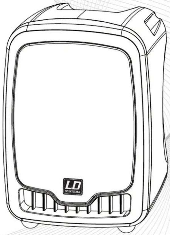
Line drawing of a portable electronic device with 'LD SYSTEMS' logo on front panel (no text or symbols beyond branding)LD ROADBOY 6.5
PORTABLE SOUND SYSTEM 25 W
Thank you for choosing LD-Systems!
We have designed this product to operate reliably over many years. Therefore LD-Systems guarantees for high quality products with its name and many years of experience as a producer.
Please, take a few moments to read these instructions carefully, as we want you to enjoy your new LD-Systems products quickly and to the fullest.
For information about LD-Systems check out our website WWW.LD-SYSTEMS.COM
LD ROADBOY 6.5
PORTABLE SOUND SYSTEM 25 W
natural_image
Line drawing of a portable electronic device with 'LD SYSTEMS' logo on front panel (no text or symbols beyond branding)PREVENTIVE MEASURES:
- Please read the attached safety instructions as well as the following instructions carefully.
- Please keep all the instructions.
- Please use the device only as intended.
- Please respect the valid waste management rules. Please deliver the packaging divided into plastic and paper/ cardboard to the recycling management.
- Please refer all servicing to qualified personnel only if the device is damaged, exposed to liquid/rain or if it does not operate normally.
- Please, do not expose to any kind of heat such as ovens, radiators, or any other devices (incl. amplifiers). Please check for enough distance between amplifiers and walls, racks, etc. to prevent overheating.
- After connection please check the wiring to prevent any kind of accident or damage. Please never use any kind of damaged cable and wiring.
- Only use authorized and stable stands, brackets, shelves, tables etc.. for installations. Please check for adequate stability against collapse.
CAUTION:

To reduce the risk of electric shock, do not remove cover (or back). No user serviceable parts inside. Refer servicing to qualified personnel.
The lightning flash with arrowhead symbol within an equilateral triangle is intended to alert the user to the presence of uninsulated "dangerous voltage" within the product's enclosure that may be of sufficient magnitude to constitute a risk to persons.
The exclamation mark within an equilateral triangle is intended to alert the user to the presence of important operating and maintenance (servicing) instructions in the literature accompanying the appliance.
CAUTION! HIGH VOLUME!
You will operate this system for professional use. Therefore the commercial use of this equipment is liable to the rules and regulations of the Accident Prevention & Insurance Association of your industry sector. Adam Hall as a manufacturer is bound to inform you formally about the existence of eventual sanitary risks.
These speakers are able to induce high acoustic sound pressure levels. 85 db is by law the maximum audio pressure level which your ear can be exposed to during a work day. It was set according to the technical expertise of the occupational medicine as a basis for the noise rating level. Higher sound levels or longer exposition times could damage your ear. The time of exposition by higher sound pressure levels should be shortened in order to prevent from ear damages. Here are a few reliable warning signals which show that you have exposed yourself for a too long period to excessive sound pressure levels:
- You hear bell- or whistling sounds!
- You have the impression that you can't hear high tones anymore!
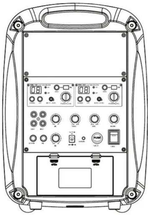
BACK PANEL:
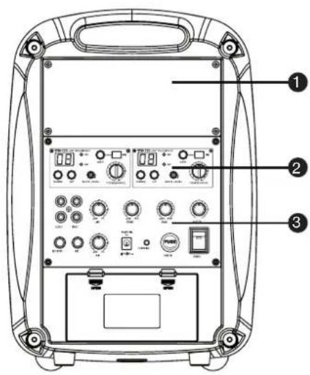
① CD PLAYER
Digital Slot-In CD Player with USB Input interface. CD Player with anti-shock function.
Supported files (CD Player and USB Player):
Audio CD, MP3, WMA
② WIRELESS RECEIVER MODULE
The Roadboy 6.5 disposes of one wireless receiver module. You can install a second receiver module if you wish to use a second microphone simultaneously.
3 CONTROL PANEL
Volume Control: Master, Wired Mic 1 & 2, Line-In
EQ: Bass, Treble
RCA Phono In & Out
Powered output for external speaker
LED Indicator: Low Battery power (red), battery
charging (green blinking), battery fully charged (green).
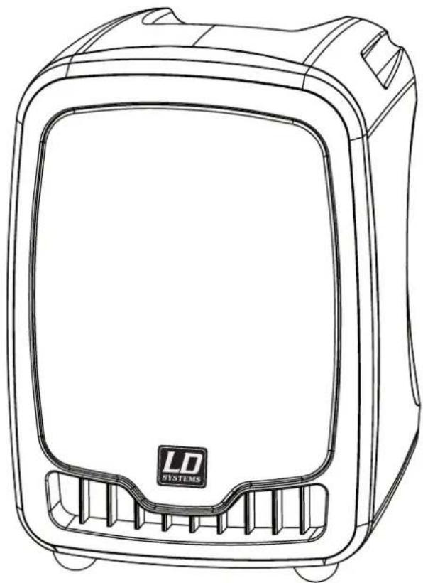
SYSTEM COMPONENTS:
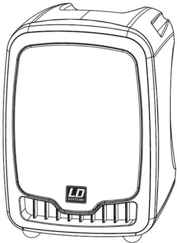
Roadboy
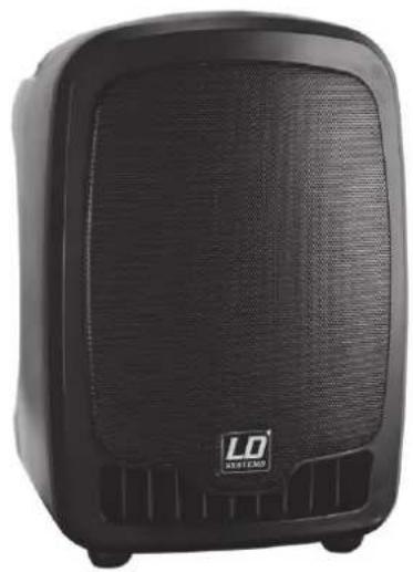
natural_image
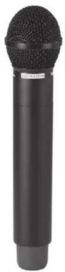
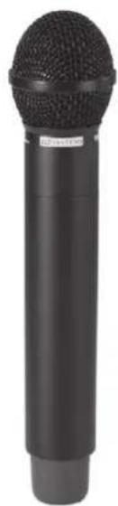
Black portable electronic device with visible grille and speaker grille (no text or symbols)Handheld Microphone
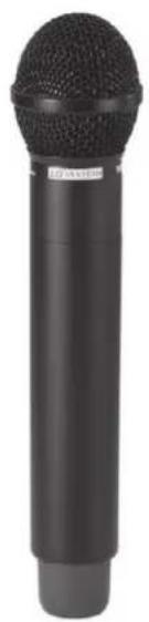
natural_image
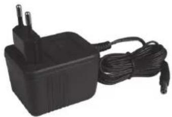
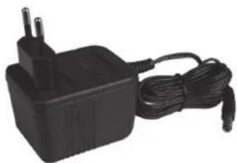
Black handheld microphone with textured body and cylindrical shaft (no visible text or symbols)Power Supply Unit
natural_image
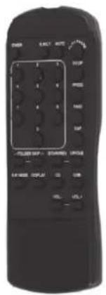
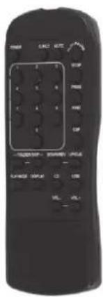
Black electric power adapter with two leads and a cord, no visible text or symbolsRemote Control
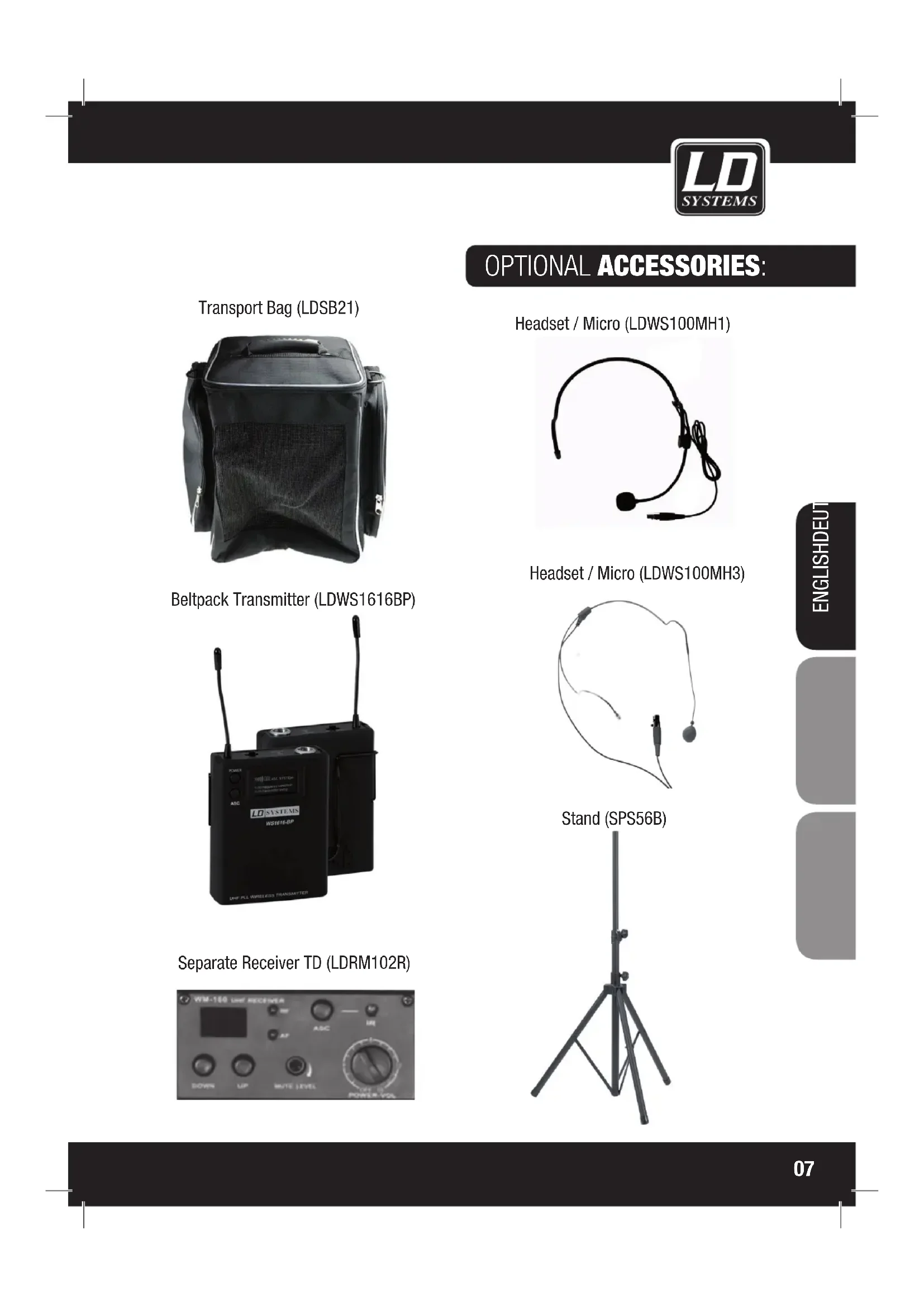
OPTIONAL ACCESSORIES:
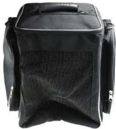
Transport Bag (LDSB21)
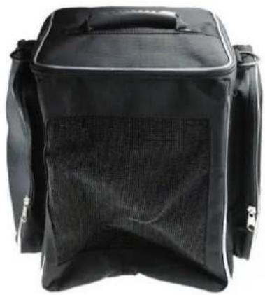
natural_image
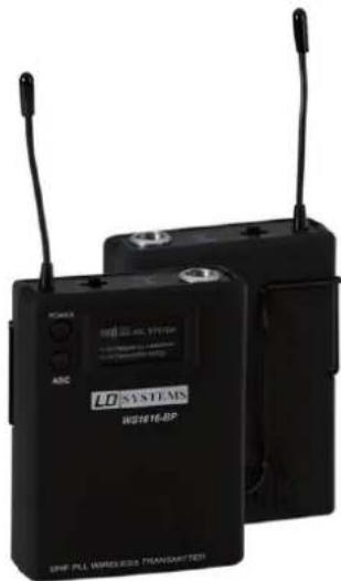
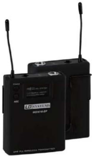
Black rectangular backpack with mesh back cover, no visible text or symbolsBeltpack Transmitter (LDWS1616BP)
natural_image
Two black wireless transmitters with visible signal waves and control buttons (no readable text or symbols)Separate Receiver TD (LDRM102R)
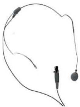
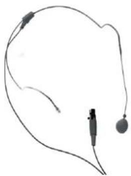
Headset / Micro (LDWS100MH1)

natural_image
Simple line drawing of a headset with earplugs (no text or symbols)Headset / Micro (LDWS100MH3)
natural_image
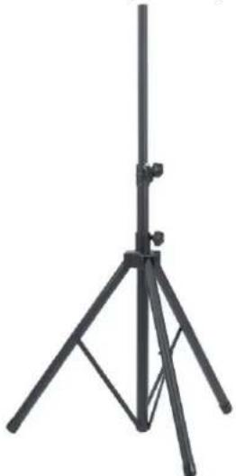
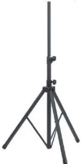
Simple line drawing of a medical or electronic device with wires and connectors (no text or symbols)Stand (SPS56B)
natural_image
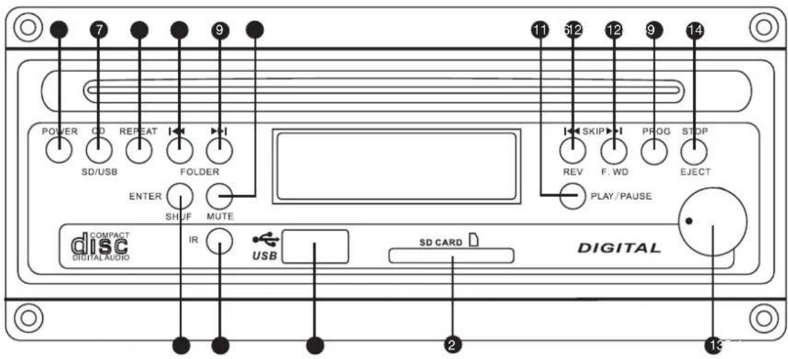
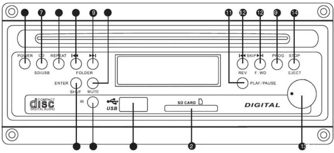
Black tripod-mounted stand with adjustable legs and support structure (no text or symbols visible)CD PLAYER:
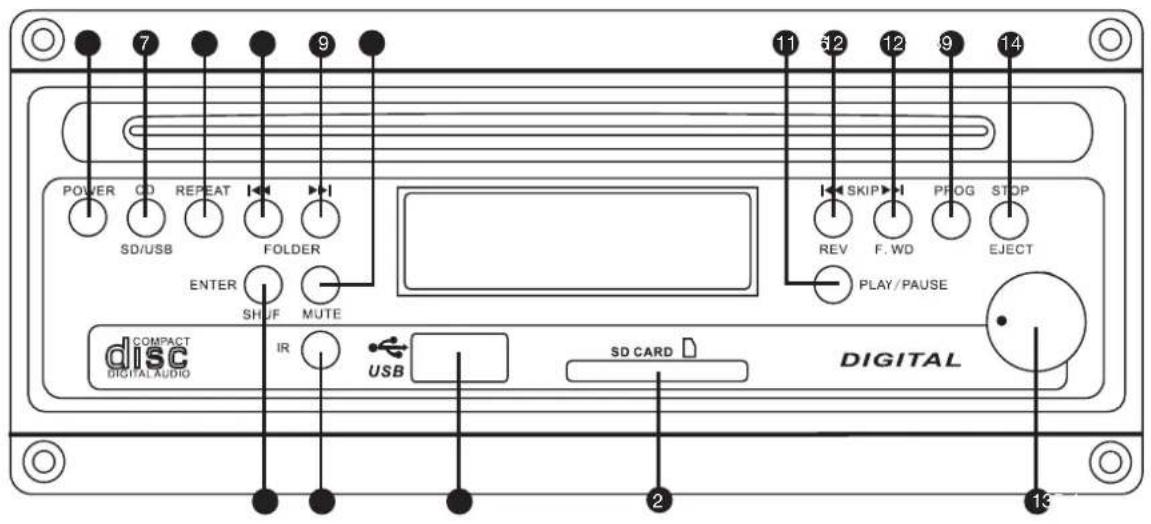
① VOLUME BUTTON
Volume button is to control outgoing volume from CD Player to amplifier.
② SD CARD READER
SD Card Input. Supports MP3 and WMA files. Only for SD Cards.
③ USB SOCKET
USB 1.1 Input. Supports MP3 and WMA files. Only for USB Memory Sticks.
4 IR
Infrared receiver for the remote control.
⑤ ENTER SHUF
Program and Shuffle mode.
6 POWER BUTTON
Press this button to turn the device on. press the button again to turn it off.
⑦ CD / SD / USB SWITCH BUTTON
Press this button to switch between CD Player, USB Stick and SD Card mode.
8 REPEAT
IN USB, SD, CD Mode the repeat modes are shown in this order.

flowchart
graph LR
    A["PLAY ALL"] --> B["RANDOM"]
    B --> C["REPEAT TRACK"]
    C --> D["REPEAT FOLDER"]
    D --> E["PLAY ALL"]
    A --> F["REPEAT ALL"]
    F --> G["RANDOM REPEAT"]
    G --> H["PLAY ALL"]
In Audio CD Mode the repeat modes are shown in this order

PLAY ALL RANDOM
REPEAT ALL

REPEAT TRACK
RANDOM REPEAT

PLAY ALL
⑨ FOLDER (LEFT/RIGHT) BUTTONS
Available in USB, MP3 CD and SD Card Mode
In Stop Mode: Use the FOLDER (LEFT/RIGHT) Buttons to go to the previous/next folder.
In Play Mode: Use the FOLDER (LEFT/RIGHT) Buttons to go to the first file of the previous/next folder.
10 MUTE
Press this button to mute the sound. Press the button again to unmute.
11 PLAY / PAUSE
Available in SD, CD and USB Mode.
In stop mode: Press Play/Pause to start playing.
In play mode: Press Play/Pause to pause playing. Press once again to resume play mode.
12 SKIP (LEFT/RIGHT) BUTTONS
In Play and Stop Mode, press SKIP (LEFT/RIGHT) to go to the previous /next track.
In Play Mode keep the SKIP button pressed to fast forward (SKIP RIGHT) or fast reverse (SKIP LEFT) a track.
13 PROG
The PROG Button allows you to program a playlist.
In Audio CD Mode: Press PROG to enter the Program Mode, use "SKIP" (Left or right) to run over the different available files. When the desired file is shown on the LCD screen press PROG again to add this file to the playlist. Once you added the files you wanted to the playlist press the "PLAY/PAUSE" button to play the playlist.
In MP3 CD Mode: Press PROG to enter the Program Mode, use "SKIP" (Left or right) to run over the different folders available on the MP3 CD. Press PROG to enter the folder, use "SKIP" (Left or right) to run over the different MP3/WMA files available in the folder. When the desired file is shown on the LCD screen press PROG again to add this file to the playlist. Once you added the files you wanted to the playlist press the "PLAY/PAUSE" button to play the playlist.
IN USB / SD Mode: Press PROG to enter the Program Mode, use "SKIP" (Left or right) to run over the different folders available on the USB Stick. Press PROG to enter the folder, use "SKIP" (Left or right) to run over the different MP3/WMA files available in the folder. When the desired file is shown on the LCD screen press PROG again to add this file to the playlist. Once you added the files you wanted to the playlist press the "PLAY/PAUSE" button to play the playlist.
14 STOP/EJECT
When a CD is playing, press "STOP/EJECT" to stop the playing. By pressing a second time you will eject the CD. When USB is playing, press "STOP/EJECT" to stop the playing.
CD REMOTE CONTROL:
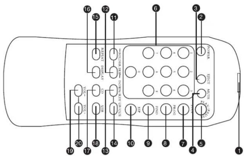
① INFRARED TRANSMITTER
② POWER ON /OFF
③ CD EJECT
4 MUTE
The Mute button allows you to completely switch off the sound of the CD / USB Player. Press once to turn the Mute function ON, press again to turn it OFF. Please Note: The Mute button doesn't stop the playing of a song or a file. It only turns the sound off.
⑤ PLAY / PAUSE
6 1-9 BUTTONS
7 STOP
8 PROG
9 FIND
10 ESP
⑪ FOLDER SKIP LEFT
⑫ FOLDER SKIP RIGHT
13 SKIP LEFT
14 SKIP RIGHT
15 REPEAT PLAYBACK MODES
16 SHOW SONG INFORMATION
17 SWITCH TO CD MODE
08 SWITCH TO USB MODE
19 VOLUME -
20 VOLUME +
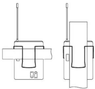
BELTPACK TRANSMITTER:
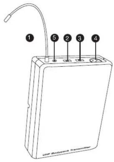
natural_image
Two technical line drawings of a device with antenna and internal components (no text or symbols)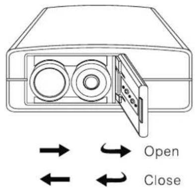
① ANTENNA
② ON/MUTE/OFF SWITCH
The middle position is the mute position
③ GAIN
Mic: Microphone Use
0: Guitar with passive pickup
-10 dB: Guitar with active pickups
4 MINI XLR INPUT
5 POWER INDICATOR
Battery status indicator
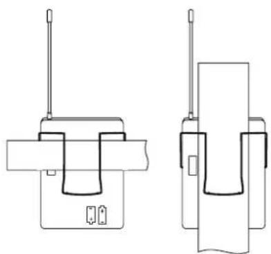
WEARING THE BELTPACK TRANSMITTER
Clip the receiver to a belt. For ultimate results, clip the receiver onto a belt by pushing the receiver down onto the belt as far as it goes.
For guitarists, attach the guitar strap "through" the receiver clip.
CHANGING THE BATTERIES
Expected life for two alkaline batteries is approximately 8 hours.
When the battery status indicator flashes red the batteries should be changed immediately as show on the left side. Please Insert 2 AA Alkaline batteries (LR6 1,5 V)
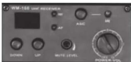
WIRELESS RECEIVER MODULE:
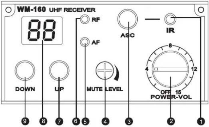
1 IR WINDOW
Sends Infra Red signals to the transmitter (hand-held Mic) in order to synchronize the frequencies
② POWER
Power switch and Volume controller
③ ASC (SYNCHRONISATION)
To connect Receiver with Transmitter.
4 MUTE LEVEL
Noise Mute adjust. Set on Factory setting. Do not change this setting.
5 AF
Shows if the module receives an audio signal
6 RF
Shows if the module receives a radio signal
7 UP
Channel Up
8 DIGITAL DISPLAY
Digital channel display
9 DOWN
Channel Down
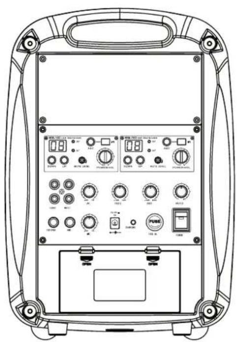
CONTROL PANEL:
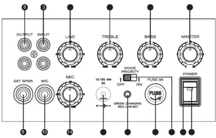
① POWER SWITCH
② POWER INDICATOR LIGHT
③ MASTER VOLUME
4 BASS
5 TREBLE
6 LINE VOLUME
⑦ RCA LINE IN
8 RCA LINE OUT
9 EXTERNAL SPEAKER OUTPUT
⑩ MICROPHONE INPUT
⑪ MICROPHONE ADJUST
⑫ DC INPUT INTERFACE
13 CHARGING / LOW BAT INDICATOR
14 FUSE
15 VOICE PRIORITY FUNCTION SWITCH
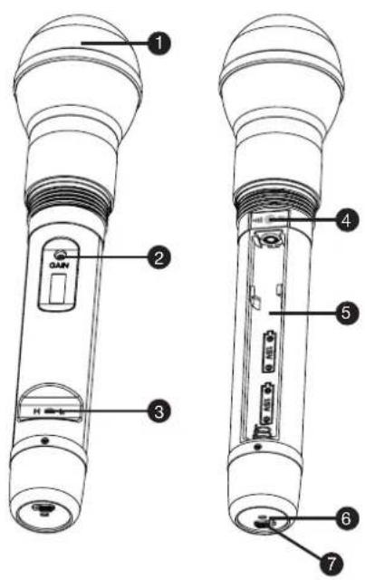
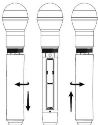
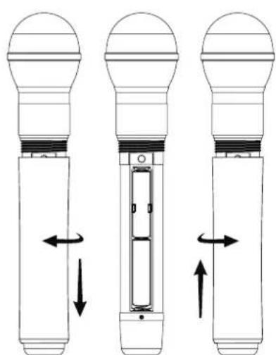
HANDHELD TRANSMITTER:
natural_image
Three technical diagrams of a device with directional arrows indicating movement or force (no text or symbols present)① MICROPHONE HEAD
② GAIN
Use this controller to adjust the microphone sensitivity.
Left decrease, right increase.
Factory settings should give you complete satisfaction.
③ RF POWER SWITCH
H stands for High power signal, L for Low power signal.
4 IR PORT
Receives the Infra Red frequencies sent by the receiver in order to synchronize and find the best transmitting frequency.
⑤ BATTERIES RACK
Please Insert 2 AA Alkaline batteries (LR6 1,5 V)
6 POWER/ASC
Green light: Power On
Green flash: IR transmission in progress
Red flash: battery low
7 ON/OFF SWITCH
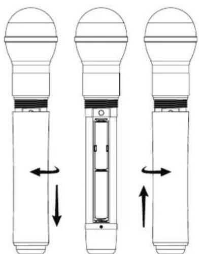
CHANGING BATTERIES
Battery life is about 8 hours. If the Low Battery indicator glows then change the batteries immediately.
TECHNICAL SPECIFICATIONS:
BASIC SPECIFICATIONS
Output power: MAX 25 W RMS / 4 Ω
Frequency response: 50Hz - 20KHz
Maximum sound pressure: 118dB
Speaker: 6.5-inch full range
Power: 200V-250V Switching power supply DC 16v/2A
Batteries: 12V / 2.9AH
THD: <0,5%
Size (W x H x D): 600 x 350 x 300
Weight: 5 kg
Receiver module: Freq: 863 MHz - 865 MHz
Operating time: 5 hours
CD PLAYER
Product type:
Compact disc digital audio system with mechanic &
electronic anti-shock CD, CD-R, CD-R/W, MP3, WMA,
USB, SD, MP3, WMA available.
Disc loading: Slot-in Type
Supply voltage: DC 12V (10\~14V)
Power consumption: Within 5W
Dimensions (W x H x D): 160mm x 147,4mm x 68,5mm
Weight:1,2 kg
RECEIVER
Channels: 16
Carrier frequency range: 863MHz - 865MHz
Audio bandwidth: 60Hz - 16kHz
THD: < 1%
Signal/noise ratio: >100dB
Modulation: FM
Dimensions: 212mm x 160mm x 44mm
Net weight: 860 g
Power requirements: 12-18volt DC / 300mA,
ext. power supply
WIRELESS MICROPHONE
Channels: 16
Carrier frequency range: 863MHz - 865MHz
Capsule type: Dynamic
Polar pattern: Cardioid
RF Output power: 10mW
Audio bandwidth: 60Hz - 16kHz
Signal/noise ratio: >102dB
Modulation: FM
Dimensions: 235mm x 54mm
Net weight: 280gr
Power requirements: 2x „AA“ -batteries
Battery Life: >10 hours
BELTPACK TRANSMITTER
Channels: 16
Carrier frequency range: 863MHz - 865MHz
RF Output power: 6mW
Max. input level: 6mV
Audio bandwidth: 60Hz - 16kHz
Signal/noise ratio: >102dB
Modulation: FM
Dimensions: 85mm x 65mm x 24mm
Net weight: 80gr
Power requirements: 2x „AA“ -batteries
Battery Life: >10 hours, depending on batteries
SYSTEM SETTINGS AND OPERATIONS:
USING MICROPHONE
Insert the 6.3 mm Phone plug to „MIC“ -input jack on back panel and be sure that the microphone is connected and the microphone is on. Use „MIC“ -level button to reach wanted balance between „MIC“ and „LINE“. Too much „MIC“ -level can cause distortion (Overdrive).
USING WIRELESS MODULE
Turn the „POWER-VOL“ -button to half way. Keep „MASTER“ -level down on zero. Set up Frequency using „ASC“ -function. Press „ASC“ -button on back panel and hold microphone or belt pack transmitter close to back panel and be sure that there is visible connection to „IR“ -infrared sensors. This takes a few seconds. Be sure that you have other module on different frequency to avoid overtaking between modules. When you have „RF“ -light visible on back panel, wireless microphone or transmitter is ready to use. When you use wireless microphone or transmitter, then „AF“ -light is flashing. Open „MASTER“ -level button to get wanted volume level.
Maximum distance between the wireless microphone or transmitter and the receiver module is around 100m.
USING „EXT. SPEAKER“
Use 6,3mm phono jack speaker cable to connect external loudspeaker. Use 4 - 8 ohm / 25 watt type. Output of amplifier is not protected for short circuit, so always keep phone jack connected to speaker to avoid short circuit. Internal loudspeaker is not active when external loudspeaker is connected.
CHARGING ROADBOY
Use 16volt/12A power supply which is included with Roadboy to use it without batteries or to charge the batteries. Charging time is 8 hours and charging procedure will be stopped automatically when battery is full.
IMPORTANT! When Roadboy is charged for first time, charging time should be 15 hours to guarantee long battery life. This procedure should be repeated every 2-3 months. Before this charging procedure battery should be empty. Batteries can be replaced only by qualified person.
If Roadboy should be permanent operated, then simply keep the Charger power supply connected to the Roadboy.
MANUFACTURER'S DECLARATIONS:
LIMITED WARRANTY
This Limited Warranty applies to the Adam Hall, LD Systems, Defender, Palmer and Eminence branded products.
The statutory warranty rights towards the seller are not affected by this guarantee. In fact, it justifies, additional independent warranty claims towards Adam Hall.
Adam Hall warrants that the Adam Hall product you have purchased from Adam Hall or from an Adam Hall authorized reseller is free from defects in materials or workmanship under normal use for a period of 2 or 5 years from the date of purchase.
The Limited Warranty Period starts on the date of purchase. In order to receive warranty services you are required to provide proof of the purchase date. Your dated sales or delivery receipt, showing the date of purchase, is your proof of the purchase date. Should products of the brands named above be in need of repair within the limited warranty period, you are entitled to warranty services according to the terms and conditions stated in this document.
This Limited Warranty extends only to the original purchaser of this Adam Hall branded product and is not transferable to anyone who obtains ownership of the Adam Hall branded product from the original purchaser. During the Limited Warranty Period, Adam Hall will repair or replace the defective component parts or the product. All component parts or hardware products removed under this Limited Warranty become the property of Adam Hall.
In the unlikely event that your Adam Hall product has a recurring failure, Adam Hall, at its discretion, may elect to provide you with a replacement unit of Adam Hall's choice that is at least equivalent to your Adam Hall branded product in hardware performance.
Adam Hall does not warrant that the operation of this product will be uninterrupted or error-free. Adam Hall is not responsible for damage that occurs as a result of your failure to follow the instructions included with the Adam Hall branded product.
This Limited Warranty does not apply,
- to wear parts (e.g. accumulator)
- to any product from which the serial number has been removed or that has been damaged or rendered defective as the result of an accident
- in case of, misuse, abuse, or other external causes
- by operation outside the usage parameters stated in the user's documentation shipped with the product
- by use of spare parts not manufactured or sold by Adam Hall
- by modification or service by anyone other than Adam Hall
These terms and conditions constitute the complete and exclusive warranty agreement between you and Adam Hall regarding the Adam Hall branded product you have purchased.
MANUFACTURER'S DECLARATIONS:
LIMITATION OF LIABILITY
If your Adam Hall branded hardware product fails to work as warranted above, your sole and exclusive remedy shall be repair or replacement. Adam Halls' maximum liability under this limited warranty is expressly limited to the lesser of the price you have paid for the product or the cost of repair or replacement of any hardware components that malfunction in conditions of normal use.
Adam Hall is not liable for any damages caused by the product or the failure of the product, including any lost profits or savings or special, incidental, or consequential damages. Adam Hall is not liable for any claim made by a third party or made by you for a third party.
This limitation of liability applies whether damages are sought, or claims are made, under this Limited Warranty or as a tort claim (including negligence and strict product liability), a contract claim, or any other claim. This limitation of liability cannot be waived or amended by any person. This limitation of liability will be effective even if you have advised Adam Hall of an authorized representative of Adam Hall of the possibility of any such damages. This limitation of liability however, will not apply to claims for personal injury.
This Limited Warranty gives you specific legal rights. You may also have other rights that may vary from state to state or from country to country. You are advised to consult applicable state or country laws for a full determination of your rights.
REQUESTING WARRANTY-SERVICE
To request warranty service for the product, contact Adam Hall or the Adam Hall authorized reseller from which you purchased the product.
EG-DECLARATION OF CONFIRMITY
These products meet the essential requirements as well as the further standards of the EU Directives 199/5/EU, 89/336/EU.
CORRECT DISPOSAL OF THIS PRODUCT (ELECTRICAL WASTE)

(Applicable in the European Union and other European countries with separate collection systems)
This marking shown on the product or its literature, indicates that it should not be disposed with other household wastes at the end of its working life. To prevent possible harm to the environment or human health from uncontrolled waste disposal, please separate this from other types of wastes and recycle it responsibly to promote the sustainable reuse of material resources.
Household users should contact either the retailer where they purchased this product, or their local government office, for details on where and how they can recycle this item in an environmentally friendly manner.
Business users should contact their supplier and check the terms and conditions of the purchase contract. This product should not be mixed with other commercial wastes for disposal
WEEE-DECLARATION
Your LD-Systems product was developed and manufactured with high quality materials and components which can be recycled and/or reused. This symbol indicates that electrical and electronic equipment must be disposed of separately from normal waste at the end of its operational lifetime.
Please dispose of this product by bringing it to your local collection point or recycling centre for such equipment. This will help to protect the environment in which we all live.
BATTERIES AND ACCUMULATORS
The supplied batteries or rechargeable batteries can be recycled. Please dispose of them as special waste or return them to your specialist dealer. In order to protect the environment, only dispose exhausted batteries.
Adam Hall GmbH, all rights reserved. The technical data and the functional product characteristics can be subject to modifications. The photocopying, the translation, and all other forms of copying of fragments or of the integrality of this user's manual is prohibited.
NOTES:
natural_image
Line drawing of a portable electronic device with 'LD SYSTEMS' label on front panel (no other text or symbols)① CD PLAYER
natural_image
Black portable electronic device with grille and speaker grille, labeled 'LD WERTGAR' (no additional text or symbols visible)Handmikrofon
natural_image
Black handheld microphone with textured body and label 'Pension' on the cap (no visible text or symbols on device body)Netzteil
natural_image
Black electronic power adapter with two leads and a cord (no visible text or symbols)natural_image
Black athletic backpack with mesh backrest and side straps (no text or symbols visible)Beltpack Sender (LDWS1616BP)
natural_image
Two black wireless transamfer devices with visible signal waves and control buttons (no readable text or symbols)natural_image
Simple line drawing of a headset with earplugs and cables (no text or symbols)Headset / Mkro (LDWS100MH3)
natural_image
Simple line drawing of a medical or electronic device with wires and connectors (no text or symbols)Stativ (SPS56B)
natural_image
Black tripod-mounted stand with adjustable legs and support structure (no text or symbols visible)CD SPIELER:
natural_image
Two technical line drawings of mechanical components with no visible text or symbols
1 ANTENNE
② EIN- / STUMM- / AUSSCHALTER
natural_image
Three technical diagrams of a light bulb device with directional arrows indicating internal components (no text or symbols)① MIKROFONKOPF
② GAIN
Disc loading: Slot-in Type
Supply voltage: DC 12V (10\~14V)
Power consumption: 5W
Abmessungen: (W x H x D): 160mm x 147,4mm x
68,5mm
Gewicht:1,2 kg
EMPFÄNGER
Kanäle: 16
Audio Ausgang: XLR balanced - 12dBv (600ohm)
/ 6,3mm jack - 16dBv (3kOhm)
Abmessungen 212mm x 160mm x 44mm
natural_image
Line drawing of a portable electronic device with 'LD SYSTEMS' label on front panel (no other text or symbols)PRÉCAUTIONS D'UTILISATION:
① LECTEUR CD
natural_image
Black industrial electronic device with visible grille and ventilation slots (no text or symbols)Micro main émetteur
natural_image
Black cylindrical microphone with textured body and label (no visible text or symbols on body)Bloc secteur
natural_image
Black electric power adapter with two leads and a cord, no visible text or symbolsTélécommande
ACCESSOIRES EN OPTION:
Housse de transport (LDSB21)
natural_image
Black rectangular backpack with mesh cover and side arm, no visible text or symbolsnatural_image
Two black wireless earphones with attached antennas and a display screen, no visible text or symbols on the devices themselves.natural_image
Line drawing of a headset with earplugs and cables (no text or symbols)natural_image
Simple line drawing of a medical device with two connectors and a bulb (no text or symbols)natural_image
Black tripod-mounted stand with adjustable support (no text or symbols visible)LECTEUR CD:
① RÉGLAGE DU VOLUME
natural_image
Two technical line drawings of a device with antenna and internal components (no text or symbols)
① ANTENNE
② MARCHE/ARRÊT ET POSITION MUTE
natural_image
Three diagrams of a light bulb device with internal components and directional arrows indicating movement (no text or symbols)① TÊTE DU MICROPHONE
② GAIN
Dimensions: 85 x 65 x 24 mm
Poids Net: 80 g
Alimentation: 2 piles LR6 (AA)
Distorsion Harmonique Totale (DHT): <1%
Rapport Signal/Bruit: >102dB
Modulation: FM
Dimensions: 212 x 160 x 44 mm
Poids Net: 860 g
Dimensions (L x H x P) : 160mm x 147,4mm x 68,5mm
Poids : 1,2 kg
ÉMETTEUR CEINTURE:
UTILISATION DU MICROPHONE
WWW.LD-SYSTEMS.COM
Adam Hall GmbH | Daimlerstrasse 9 | 61267 Neu-Anspach | Germany
Tel. +49(0)6081/9419-0 | Fax +49(0)6081/9419-1000
web: www.adamhall.com | e-mail: mail@adamhall.com


- LD ROADBOY 6.5
- Thank you for choosing LD-Systems!
- PORTABLE SOUND SYSTEM 25 W
- PREVENTIVE MEASURES:
- CAUTION:
- CAUTION! HIGH VOLUME!
- BACK PANEL:
- ① CD PLAYER
- ② WIRELESS RECEIVER MODULE
- CONTROL PANEL
- SYSTEM COMPONENTS:
- OPTIONAL ACCESSORIES:
- CD PLAYER:
- ① VOLUME BUTTON
- ② SD CARD READER
- ③ USB SOCKET
- IR
- ⑤ ENTER SHUF
- POWER BUTTON
- ⑦ CD / SD / USB SWITCH BUTTON
- REPEAT
- ⑨ FOLDER (LEFT/RIGHT) BUTTONS
- MUTE
- PLAY / PAUSE
- SKIP (LEFT/RIGHT) BUTTONS
- PROG
- STOP/EJECT
- CD REMOTE CONTROL:
- BELTPACK TRANSMITTER:
- ① ANTENNA
- ② ON/MUTE/OFF SWITCH
- ③ GAIN
- MINI XLR INPUT
- POWER INDICATOR
- WEARING THE BELTPACK TRANSMITTER
- CHANGING THE BATTERIES
- WIRELESS RECEIVER MODULE:
- IR WINDOW
- ② POWER
- ③ ASC (SYNCHRONISATION)
- MUTE LEVEL
- AF
- RF
- UP
- DIGITAL DISPLAY
- DOWN
- CONTROL PANEL:
- HANDHELD TRANSMITTER:
- ① MICROPHONE HEAD
- ② GAIN
- ③ RF POWER SWITCH
- IR PORT
- ⑤ BATTERIES RACK
- POWER/ASC
- ON/OFF SWITCH
- CHANGING BATTERIES
- TECHNICAL SPECIFICATIONS:
- BASIC SPECIFICATIONS
- CD PLAYER
- RECEIVER
- WIRELESS MICROPHONE
- BELTPACK TRANSMITTER
- SYSTEM SETTINGS AND OPERATIONS:
- USING MICROPHONE
- USING WIRELESS MODULE
- USING „EXT. SPEAKER“
- CHARGING ROADBOY
- MANUFACTURER'S DECLARATIONS:
- LIMITED WARRANTY
- LIMITATION OF LIABILITY
- REQUESTING WARRANTY-SERVICE
- EG-DECLARATION OF CONFIRMITY
- CORRECT DISPOSAL OF THIS PRODUCT (ELECTRICAL WASTE)
- WEEE-DECLARATION
- BATTERIES AND ACCUMULATORS
- CD SPIELER:
- ANTENNE
- ② EIN- / STUMM- / AUSSCHALTER
- ① MIKROFONKOPF
- EMPFÄNGER
- PRÉCAUTIONS D'UTILISATION:
- ① LECTEUR CD
- ACCESSOIRES EN OPTION:
- LECTEUR CD:
- ① RÉGLAGE DU VOLUME
- ① ANTENNE
- ② MARCHE/ARRÊT ET POSITION MUTE
- ① TÊTE DU MICROPHONE
- ÉMETTEUR CEINTURE:
- UTILISATION DU MICROPHONE
Brand : LD Systems
Model : LDRB65
Category : Sound system