
EU30IS - Generator Honda - Free user manual and instructions
Find the device manual for free EU30IS Honda in PDF.
| Product type | Portable inverter generator |
| Brand | Honda |
| Model | EU30IS |
| Engine | Honda GX200, 4-stroke single cylinder, 196 cc |
| Rated power (AC) | 2.8 kVA (230 V, 12.2 A) |
| Maximum power (AC) | 3.0 kVA |
| DC output | 12 V, 12 A (battery charging) |
| Fuel tank capacity | 13.0 liters |
| Runtime at rated load | Approximately 6 hours (estimate) |
| Dimensions (L × W × H) with wheels | 658 × 482 × 570 mm |
| Dry weight | 61.2 kg |
| Noise level (acoustic pressure) | 74 dB(A) at 1.60 m |
| Noise level (guaranteed acoustic power) | 91 dB(A) |
| Engine speed | 2,500 - 3,800 rpm (Eco Throttle OFF: 3,500 - 3,800 rpm) |
| Engine oil | SAE 10W-30, API SE or higher, 0.55 L |
| Spark plug | BPR6ES (NGK) or W20EPR-U (DENSO) |
| Fuse (EU30IS) | 5 A |
| Starting battery | 12 V, 8.6 Ah/10 HR |
| Eco Throttle system | Yes, reduces idle speed for fuel savings |
| Parallel operation | Possible with special cable (sold separately), max power 6.0 kVA |
| Protection | AC circuit protector, oil alert system, overload and output indicators |
| AC outlet | 230 V, 50 Hz outlet (type depends on variant: F, G, GW, etc.) |
| Warranty | Manufacturer warranty, genuine parts recommended |
Frequently Asked Questions - EU30IS Honda
User questions about EU30IS Honda
0 question about this device. Answer the ones you know or ask your own.
Ask a new question about this device
Download the instructions for your Generator in PDF format for free! Find your manual EU30IS - Honda and take your electronic device back in hand. On this page are published all the documents necessary for the use of your device. EU30IS by Honda.
USER MANUAL EU30IS Honda
GENERATOR EU26i/EU30is

OWNER'S MANUAL
MANUEL DE L'UTILISATEUR
BEDIENUNGSANLEITUNG
MANUAL DE EXPLICACIONES
Honda EU26i·EU30is
OWNER'S MANUAL
Original instructions
MANUEL DE L'UTILISATEUR
Notice originale
Thank you for purchasing a Honda generator.
This manual covers operation and maintenance of the EU26i and EU30is generators.
All information in this publication is based on the latest product information available at the time of approval for printing.
Honda Motor Co., Ltd. reserves the right to make changes at any time without notice and without incurring any obligation.
No part of this publication may be reproduced without written permission.
This manual should be considered a permanent part of the generator and should remain with it if it is resold.
Pay special attention to statements preceded by the following words:
WARNING Indicates a strong possibility of severe personal injury or death if instructions are not followed.
CAUTION: Indicates a possibility of personal injury or equipment damage if instructions are not followed.
NOTE: Gives helpful information.
If a problem should arise, or if you have any questions about the generator, consult an authorized Honda dealer.
WARNING
Honda generator is designed to give safe and dependable service if operated according to instructions. Read and understand the Owner's Manual before operating the generator. Failure to do so could result in personal injury or equipment damage.
The illustrations herein are mainly based on: EU type
- The illustration may vary according to the type.
1.SAFETYINSTRUCTIONS 3
2.SAFETY LABEL LOCATIONS. 7
CE mark and noise label locations 11
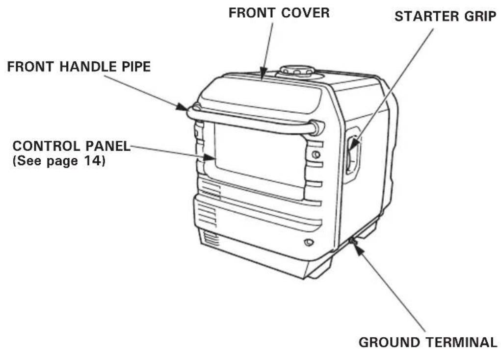
3.COMPONENT IDENTIFICATION 12
4.PRE-OPERATION CHECK 16
5. STARTING THE ENGINE 21
High altitude operation 27
6.GENERATOR USE. 28
7.STOPPING THE ENGINE 41
8.MAINTENANCE 43
9.TRANSPORTING/STORAGE 54
10.TROUBLESHOOTING 56
11.SPECIFICATIONS 58
12.WIRING DIAGRAM 62
SWITCH CONNECTIONS 63
RECEPTACLE. 64
MAJOR Honda DISTRIBUTOR ADDRESSES . . . . . . . . . . . . . . . . . . . . . . . . . . . . . . . . . . . . . . . . . . . . . . . . . . . . . . .
"EC Declaration of Conformity"
CONTENT OUTLINE... inside back cover
IMPORTANT SAFETY INFORMATION
Honda generators are designed for use with electrical equipment that has suitable power requirements. Other uses can result in injury to the operator or damage to the generator and other property.
Most injuries or property damage can be prevented if you follow all instructions in this manual and on the generator. The most common hazards are discussed below, along with the best way to protect yourself and others.
Never attempt to modify the generator. It can cause an accident as well as damage to the generator and appliances.
- Do not connect an extension to the muffler.
- Do not modify the intake system.
- Do not adjust the governor.
- Do not remove the control panel or do not change the wiring of the control panel.
Operator Responsibility
Know how to stop the generator quickly in case of emergency.
Understand the use of all generator controls, output receptacles, and connections.
Be sure that anyone who operates the generator receives proper instruction. Do not let children operate the generator without parental supervision.
Be sure to observe the instructions in this manual for how to use the generator and maintenance information. Ignoring or improperly following the instructions can cause an accident such as an electric shock, and the condition of the exhaust gas may deteriorate.
Obey all applicable laws and regulations where the generator is used.
Gasoline and Oil is toxic. Follow the instructions provided by each manufacturer before use.
Place the generator on a firm level place before operation.
Do not operate the generator with any cover removed. You may get your hand or foot caught in the generator and it may cause accident.
Consult your authorized Honda dealer for disassembly and service of the generator that are not covered in this manual.
Carbon Monoxide Hazards
Exhaust contains poisonous carbon monoxide, a colorless, odorless gas. Breathing exhaust can cause loss of consciousness and may lead to death.
If you run the generator in an area that is confined, or even partially enclosed area, the air you breathe could contain a dangerous amount of exhaust gas.
Never run your generator inside a garage, house, or near open windows or doors.
Electric Shock Hazards
The generator produces enough electric power to cause a serious shock or electrocution if misused.
Using a generator or electrical appliance in wet conditions, such as rain or snow, or near a pool or sprinkler system, or when your hands are wet, could result in electrocution.
Keep the generator dry.
If the generator is stored outdoors, unprotected from the weather, check all of the electrical components on the control panel before each use. Moisture or ice can cause a malfunction or short circuit in electrical components that could result in electrocution.
If you get an electric shock, consult a doctor and have medical treatment immediately.
Fire and Burn Hazards
Do not use the generator in areas with a high risk of fire.
The exhaust system gets hot enough to ignite some materials.
- Keep the generator at least 1 meter (3 feet) away from buildings and other equipment during operation.
- Do not enclose the generator in any structure.
- Keep flammable materials away from the generator.
Some parts of the internal combustion engine are hot and may cause burns. Pay attention to the warnings on the generator.
The muffler becomes very hot during operation and remains hot for a while after stopping the engine. Be careful not to touch the muffler while it is hot. Let the engine cool before storing the generator indoors.
Do not pour the water directly on the generator to put out the fire when it occurs. Use an appropriate fire extinguisher specially designed for electric fire or oil fire.
If you inhale fumes produced by an accidental fire with the generator, consult a doctor and have medical treatment immediately.
Refuel With Care
Gasoline is extremely flammable, and gasoline vapor can explode. Allow the engine to cool if the generator has been in operation.
Refuel only outdoors in a well ventilated area with the engine off.
Do not refuel during operation.
Do not overfill the fuel tank.
Never smoke near gasoline, and keep other flames and sparks away.
Always store gasoline in an approved container.
Make sure that any spilled fuel has been wiped up before starting the engine.
Explosion proof
This generator is not complaint with explosion proof.
Disposal
To protect the environment, do not dispose of the used generator, battery, engine oil, etc. carelessly by leaving them in the waste.
Observe the local laws or regulations or consult your authorized Honda generator dealer to dispose of these parts.
Please dispose of used motor oil in a manner that is compatible with the environment. We suggest you take it in a sealed container to your local service station for reclamation. Do not throw it in the trash or pour it on the ground.
An improperly disposed battery can hurt the environment. Always confirm local regulations for battery disposal. Contact your servicing dealer for a replacement.
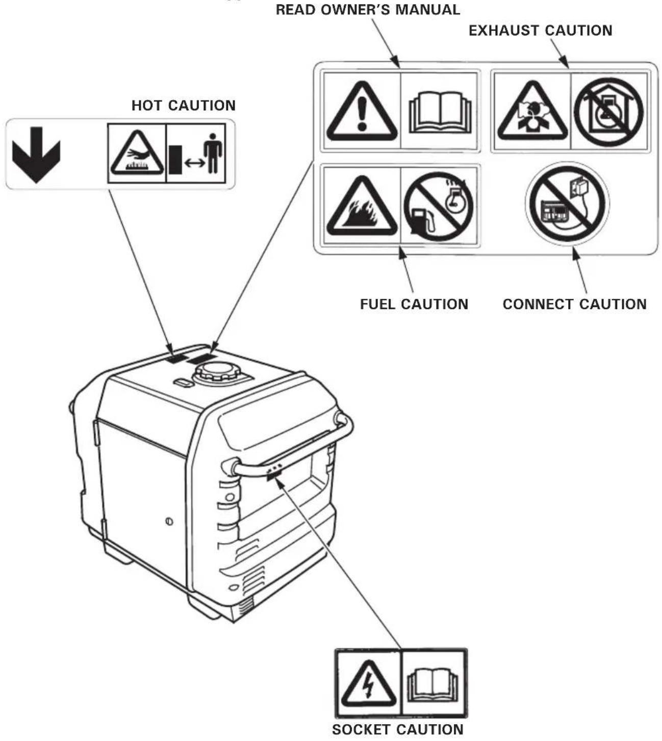
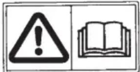
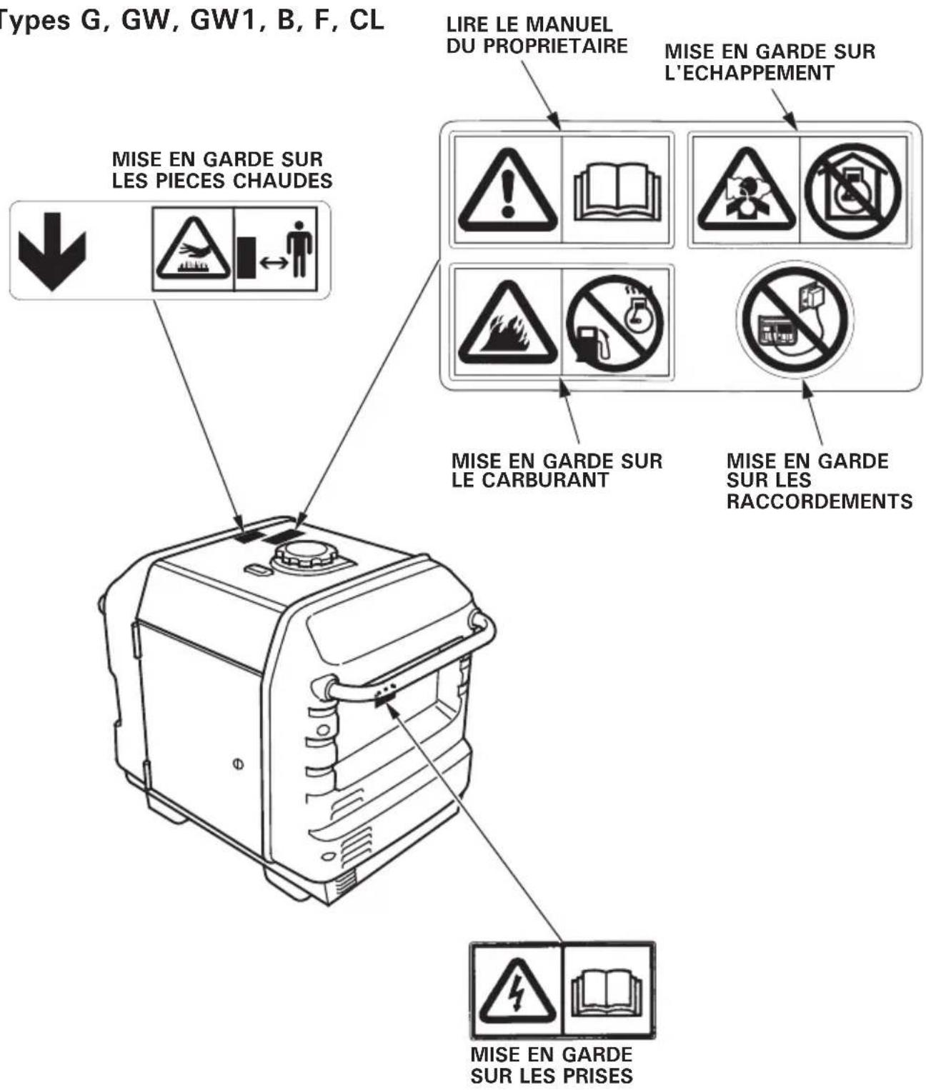
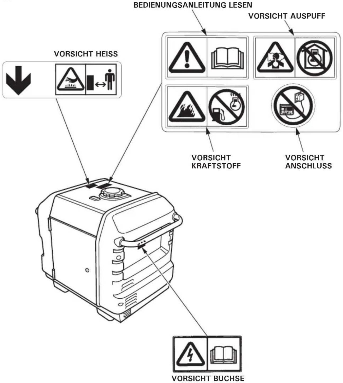
These labels warn you of potential hazards that can cause serious injury. Read the labels and safety notes and precautions described in this manual carefully.
If a label comes off or becomes hard to read, contact your servicing dealer for a replacement.
G, GW, GW1, B, F, CL types
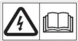
- Honda generator is designed to give safe and dependable service if operated according to instructions.
Read and understand the Owner's Manual before operating the generator. Failure to do so could result in personal injury or equipment damage.
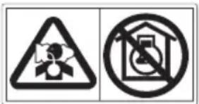
- Exhaust contains poisonous carbon monoxide, a colorless, odorless gas. Breathing carbon monoxide can cause loss of consciousness and may lead to death.
- If you run the generator in an area that is confined, or even partially enclosed area, the air you breathe could contain a dangerous amount of exhaust gas.
- Never run your generator inside a garage, house or near open windows or doors.
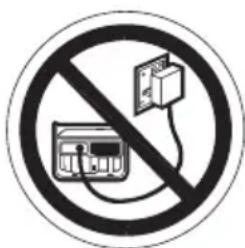
- Improper connections to a building's electrical system can allow current from the generator to backfeed into the utility lines.
Such backfeed may electrocute utility company workers or others who contact the lines during a power outage, and the generator may explode, burn, or cause fires when utility power is restored.
Consult the utility company or a qualified electrician prior to making any power connections.
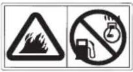
Gasoline is highly flammable and explosive. Turn the engine off and let it cool before refueling.
- Connect and remove the receptacle box for parallel operation with the engine stopped.
- For single operation, the receptacle box for parallel operation must be removed.
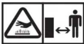
- A hot exhaust system can cause serious burns. Avoid contact if the engine has been running.
U type
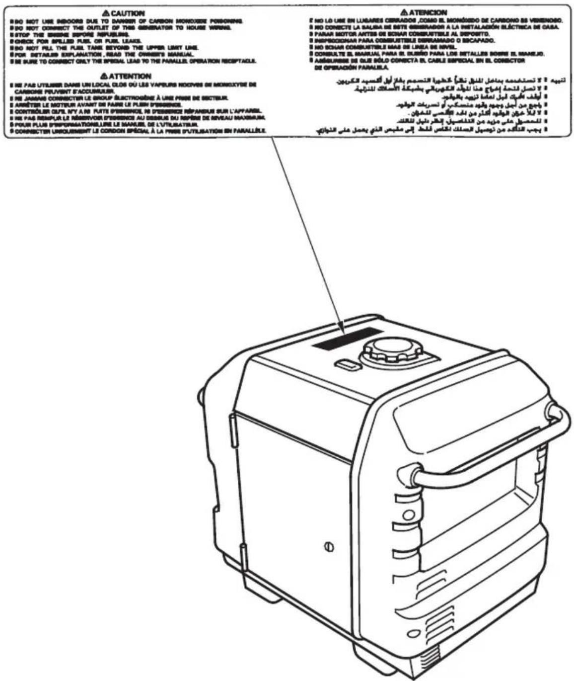
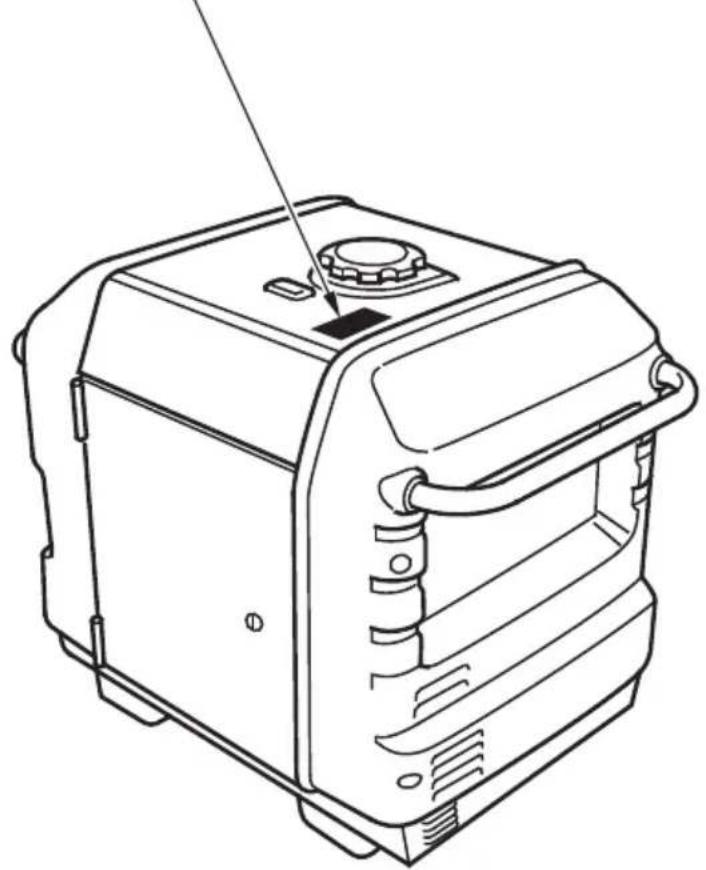
- CE mark and noise label locations
G, GW, GW1, B, F, CL types
- CE MARK and NOISE LABEL
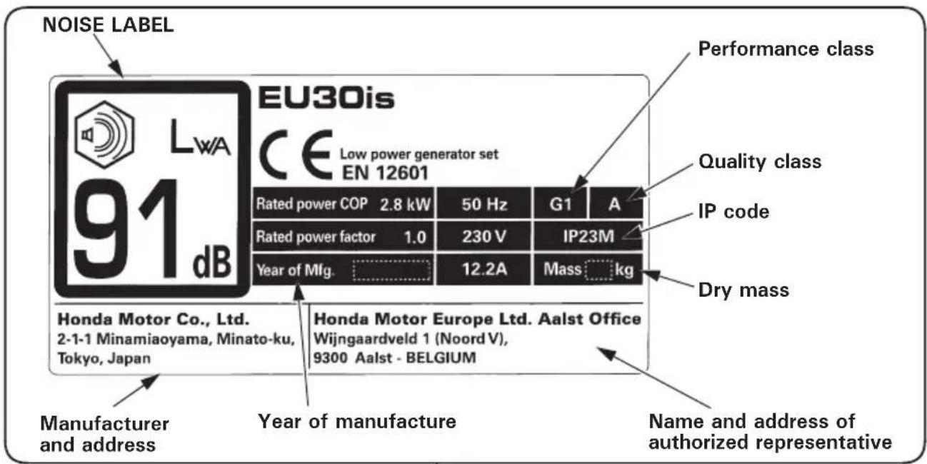
[Example: EU30is]
WHEEL TYPE>
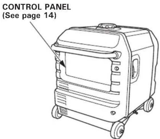
NOTE:
The generator may become unstable if all four wheels are not firmly on the ground.
Confirm that all four wheels are firmly on the ground before operation.
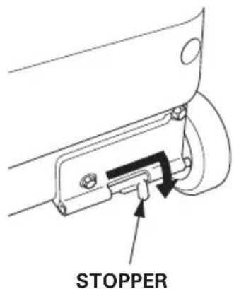
Raise the stopper lever and slide the stopper in the direction of the arrow so that it enters the hole in the wheel and then lower the stopper lever.
Confirm that the wheel is locked.
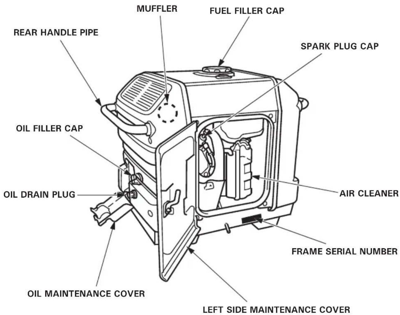
Record the frame serial number in the space below. You will need this serial number when ordering parts.
Frame serial number:
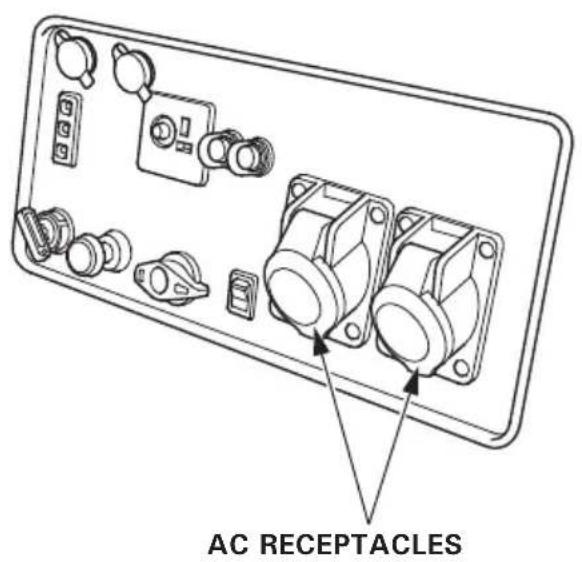
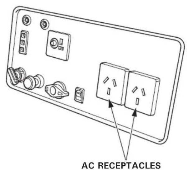
CONTROL PANEL
F, G, GW, CL types
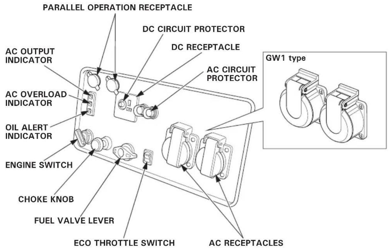
B type U type
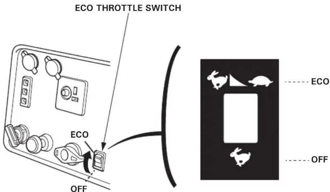
Eco Throttle
ECO:
Engine speed is kept at idle automatically when the electrical appliance is disconnected and it returns to the proper speed by the electrical load when electrical appliance is connected. This position is recommended to minimize the fuel consumption while in operation.
NOTE:
- When high electrical load appliances is connected simultaneously, turn the Eco Throttle switch to the OFF position to reduce voltage changes.
- Eco Throttle system does not operate sufficiently if the electrical appliance requires the momentary electric power.
OFF:
Eco Throttle system does not operate. Engine speed is kept in the range on the Engine speed (with eco throttle off) in the "SPECIFICATION" page.
CAUTION:
Be sure to check the generator on a level surface with the engine stopped.
- Check the engine oil level.
CAUTION:
Using non detergent oil or 2-stroke engine oil could shorten the engine's service life.
Recommended oil
Use 4-stroke motor oil that meets or exceeds the requirements for API service category SE or later (or equivalent). Always check the API service label on the oil container to be sure it includes the letters SE or later (or equivalent).
Read the instruction on the oil container before use.
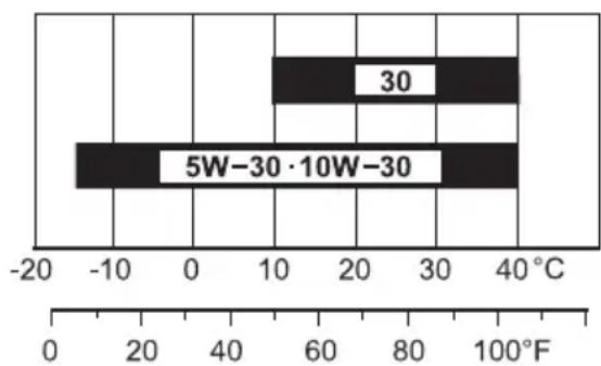
AMBIENT TEMPERATURE
SAE 10W-30 is recommended for general use. Other viscosities shown in the chart may be used when the average temperature in your area is within the indicated range.
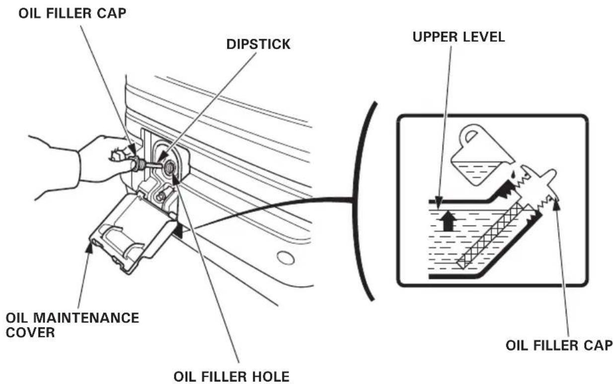
Open the oil maintenance cover.
Remove the oil filler cap, and wipe the dipstick with a clean rag. Check the oil level by inserting the dipstick in the oil filler hole without screwing it in.
If the oil level is below the end of the dipstick, refill with recommended oil up to the top of the oil filler neck.
CAUTION:
Running the engine with insufficient oil can cause serious engine damage.
NOTE:
The Oil Alert system will automatically stop the engine before the oil level falls below the safe limit. However, to avoid the inconvenience of an unexpected shutdown, it is still advisable to visually inspect the oil level regularly.
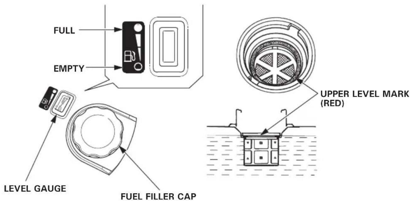
2. Check the fuel level.
Check the fuel level gauge. Refill the fuel tank if the fuel level is low. After refueling, tighten the fuel filler cap securely. Use automotive unleaded gasoline with a Research Octane Number of 91 or higher (a Pump Octane Number of 86 or higher). Never use stale or contaminated gasoline or an oil/gasoline mixture. Avoid getting dirt or water in the fuel tank.
WARNING
-
Gasoline is extremely flammable and is explosive under certain conditions.
-
Refuel in a well ventilated area with the engine stopped. Do not smoke or allow flames or sparks in the area where the engine is refueled or where gasoline is stored.
-
Do not overfill the fuel tank (there should be no fuel above the upper level mark). After refueling, make sure the fuel filler cap is closed properly and securely.
-
Be careful not to spill fuel when refueling. Spilled fuel or fuel vapor may ignite. If any fuel is spilled, make sure the area is dry before starting the engine.
-
Avoid repeated or prolonged contact with skin or breathing of vapor. KEEP OUT OF REACH OF CHILDREN.
NOTE:
Gasoline spoils very quickly depending on factors such as light exposure, temperature and time.
In worst cases, gasoline can be contaminated within 30 days.
Using contaminated gasoline can seriously damage the engine (carburetor clogged, valve stuck).
Such damage due to spoiled fuel is disallowed from coverage by the warranty.
To avoid this please strictly follow these recommendations:
- Only use specified gasoline (see page 18).
- Use fresh and clean gasoline.
- To slow deterioration, keep gasoline in a certified fuel container.
- If long storage (more than 30 days) is foreseen, drain fuel tank and carburetor.
Gasolines Containing Alcohol
If you decide to use a gasoline containing alcohol (gasohol), be sure its octane rating is at least as high as that recommended by Honda.
There are two types of "gasohol": one containing ethanol, and the other containing methanol.
Do not use gasohol that contains more than 10% ethanol.
Do not use gasoline containing more than 5% methanol (methyl or wood alcohol) and that does not also contain co-solvents and corrosion inhibitors for methanol.
NOTE:
- Fuel system damage or engine performance problems resulting from the use of gasoline that contains more alcohol than recommended is not covered under the warranty.
- Before buying gasoline from an unfamiliar station, first determine if the gasoline contains alcohol, if it does, find out the type and percentage of alcohol used.
If you notice any undesirable operating symptoms while using a particular gasoline. Switch to a gasoline that you know contains less than the recommended amount of alcohol.
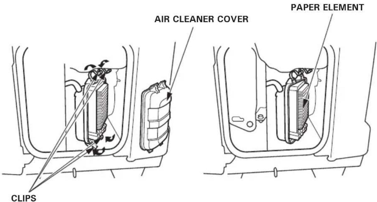
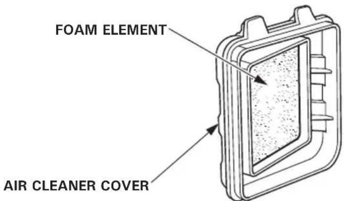
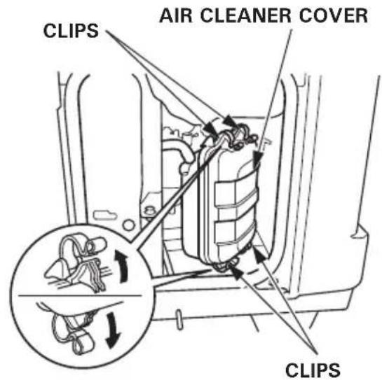
3. Check the air cleaner.
Check the air cleaner elements to be sure they are clean and in good condition.
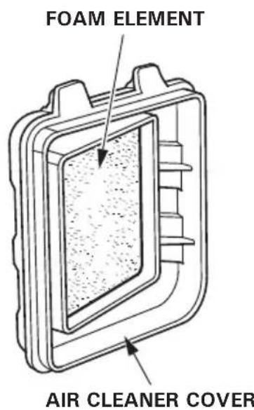
Open the left side maintenance cover. Unsnap the four clips, remove the air cleaner cover, remove the foam element from the air cleaner cover, and check the both elements.
Clean or replace the element(s) if necessary (see page 45).
CAUTION:
Never run the engine without the air cleaner element. Rapid engine wear will result from contaminants, such as dust and dirt, being drawn through the carburetor, into the engine.
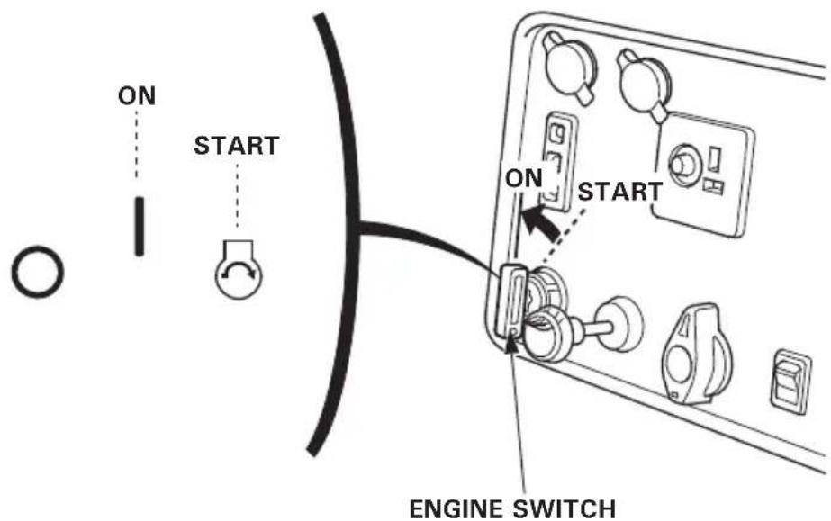
Electric starting (EU30is only)
CAUTION:
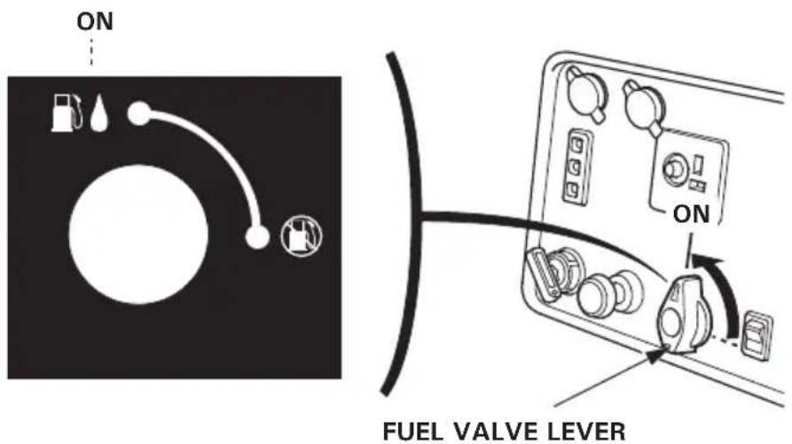
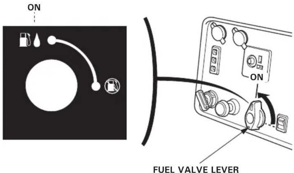
When starting the generator after adding fuel for the first time, after long-term storage, or after running out of fuel, turn the fuel valve lever to the ON position, then wait for 10 to 20 seconds before starting the engine.
Before starting the engine disconnect any load from the AC receptacle.
- Turn the fuel valve lever to the ON position.
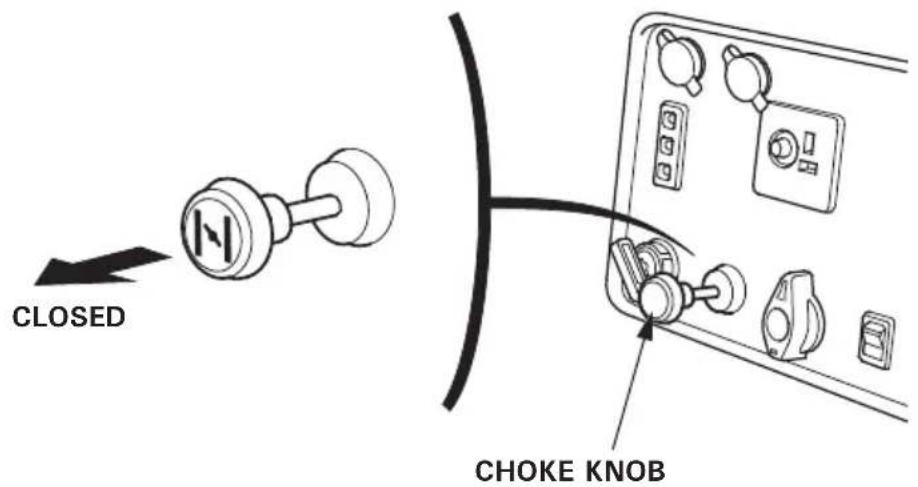
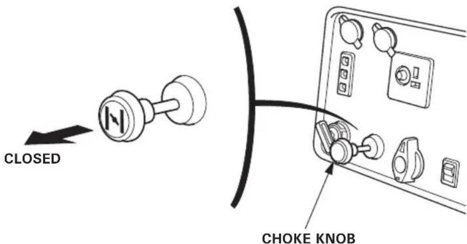
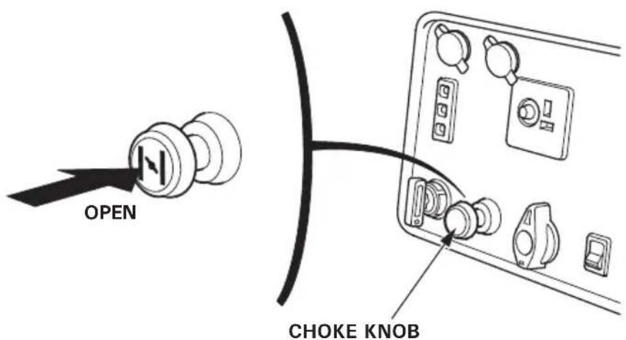
2.Pull the choke knob out to the CLOSED position.
NOTE:
Do not use the choke when the engine is warm or the air temperature is high.
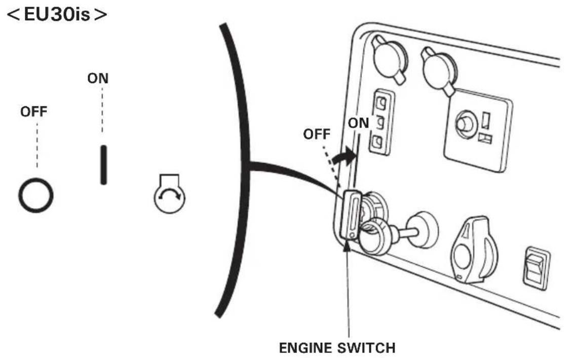
- Turn the engine switch to the START position and hold it there until the engine starts.
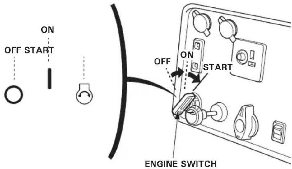
CAUTION:
Do not use the starter motor for more than 5 seconds. If the engine fails to start, release the key, and wait at least 10 seconds before operating the starter motor again.
NOTE:
When the speed of the starter motor drops after a period of time, it is an indication that the battery should be recharged.
- After the engine starts, let the engine switch return to the ON position.
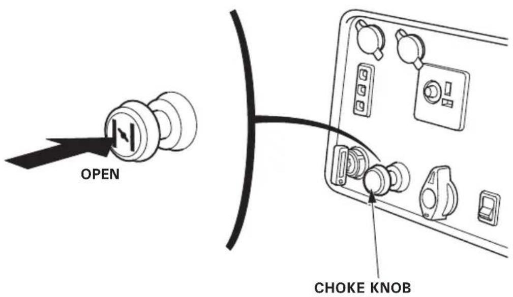
5.Push the choke knob to the OPEN position as the engine warms up.
Manual starting
CAUTION:
When starting the generator after adding fuel for the first time, after long-term storage, or after running out of fuel, turn the fuel valve lever to the ON position, then wait for 10 to 20 seconds before starting the engine.
Before starting the engine disconnect any load from the AC receptacle.
- Turn the fuel valve lever to the ON position.
2.Pull the choke knob out to the CLOSED position.
NOTE:
Do not use the choke when the engine is warm or the air temperature is high.
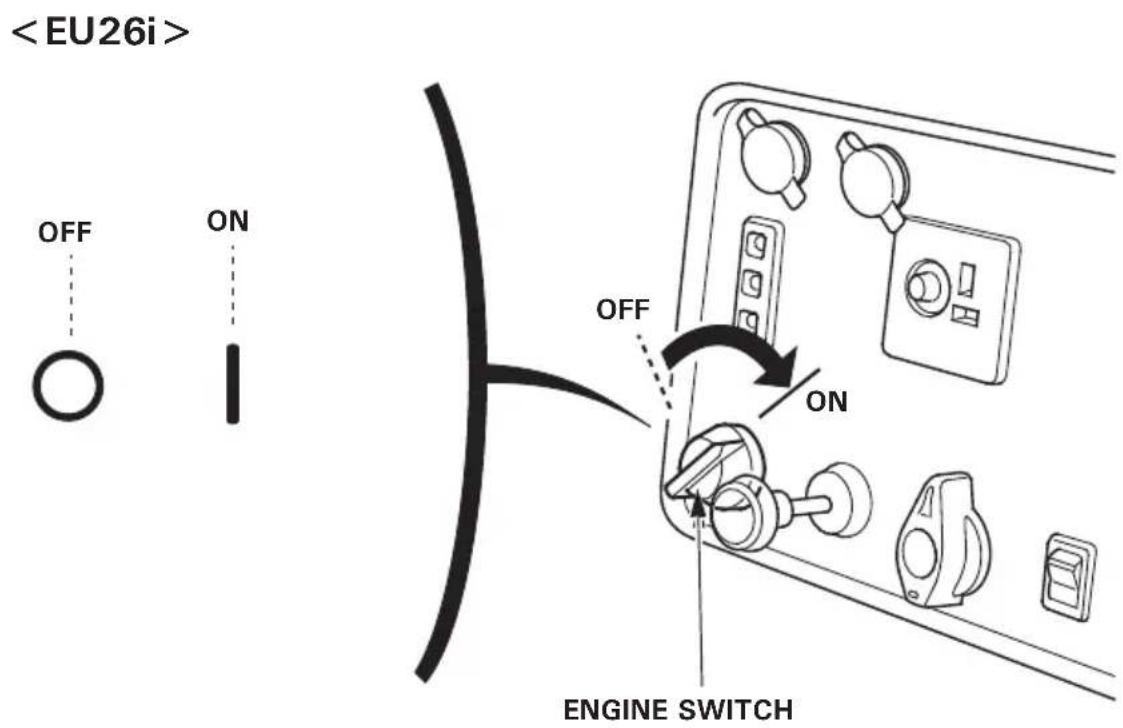
- Turn the engine switch to the ON position.
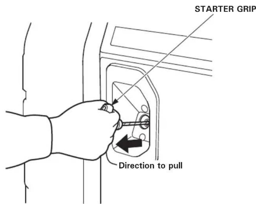
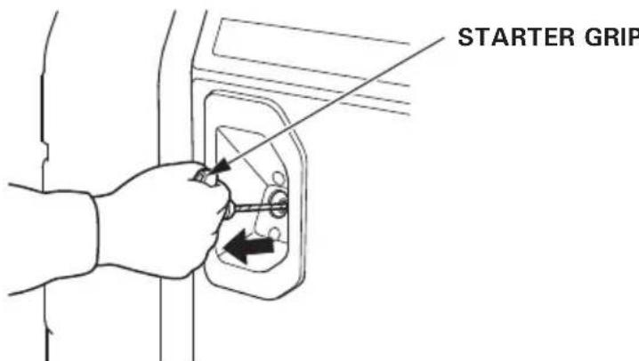
4.Pull the starter grip lightly until you feel resistance, then pull the starter grip briskly toward in the direction of the arrow as shown below.
CAUTION:
- The starter grip can be drawn back very quickly before you release it. This may pull your hand forcefully toward the engine and cause an injury.
- Do not allow the starter grip to snap back. Return it slowly by hand.
- Do not let the starter rope rub against the generator body, or the rope will wear out prematurely.
5.Push the choke knob to the OPEN position as the engine warms up.
High altitude operation
At high altitude, the standard carburetor air-fuel mixture will be excessively rich. Performance will decrease, and fuel consumption will increase.
High altitude performance can be improved by specific modifications to the carburetor. If you always operate the generator at altitudes higher than 1,500 meters (5,000 feet) above sea level, have your servicing dealer perform these carburetor modifications.
Even with suitable carburetor jetting, engine horsepower will decrease approximately 3.5% for each 300 meter (1,000 foot) increase in altitude.
The effect of altitude on the horsepower will be greater than this if no carburetor modification is made.
CAUTION:
Operation of the generator at an altitude lower than the carburetor is jetted for may result in reduced performance, overheating, and serious engine damage caused by an excessively lean air/fuel mixture.
The generator produces enough electric power to cause a serious shock or electrocution if misused.
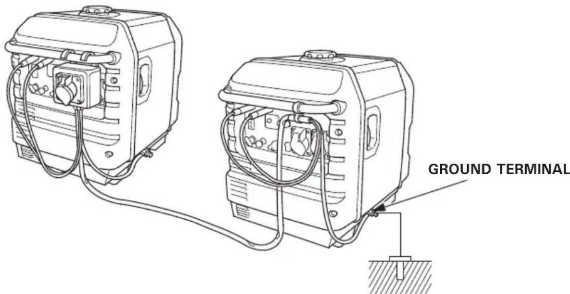
Be sure to ground the generator when the connected appliance is grounded.
To ground the terminal of the generator, GROUND TERMINAL use a copper wire with same or larger diameter than the cord of the connected appliance.
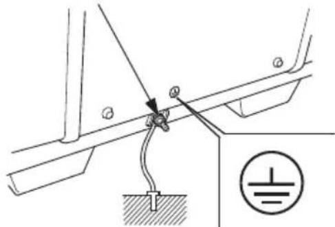
Use extension cord set with ground conductor when connecting an appliance with ground conductor.
To identify the Ground pin in the plug, see RECEPTACLE page 64.
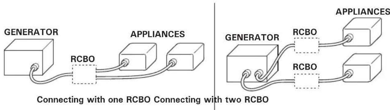
Connect a RCBO (Residual current circuit breaker with overload protection) of 30mA ground fault detection and cut-off of less than 0.4 seconds at more than 30A of output current, if you are using two or more appliance.
Follow the instructions provided by each RCBO manufacturer before use.
WARNING
Improper connections to a building's electrical system can allow current from the generator to backfeed into the utility lines.
Such backfeed may electrocute utility company workers or others who contact the lines during a power outage, and the generator may explode, burn, or cause fires when utility power is restored.
Consult the utility company or a qualified electrician prior to making any power connections.
CAUTION:
- Do not exceed the current limit specified for any one receptacle.
- Do not modify or use the generator for other purposes than it is intended for. Also observe the following when using the generator.
- Do not connect an extension to the exhaust pipe.
- When an extension cable is required, be sure to use a tough rubber sheathed flexible cable (IEC 245 or equivalent).
- Limit length of extension cables; 60m (200 feet) for cables of 1.5 mm^2 (0.0023 in²) and 100 m (330 feet) for cables of 2.5 mm² (0.0039 in²). Long extension cables will lower usable power due to resistance in the extension cable.
- Keep the generator away from other electric cables or wires such as commercial power supply lines.
WARNING
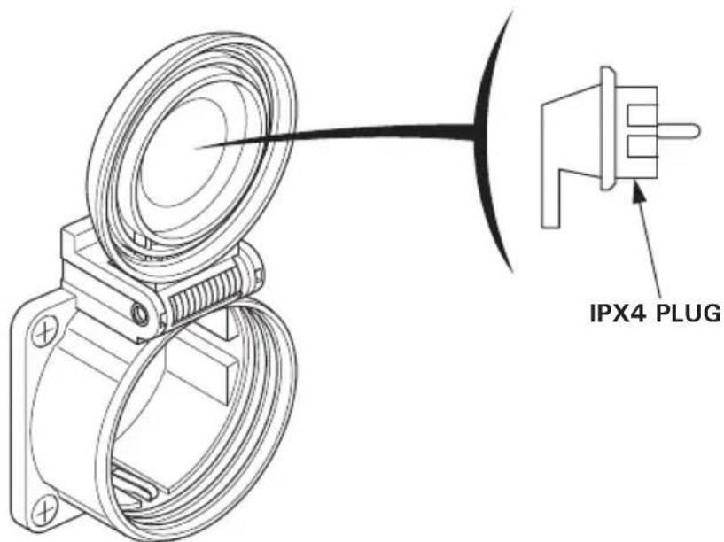
GW1 type
When connecting an angled plug, be sure to use only a IPX4 plug.
NOTE:
- The DC receptacle can be used while the AC power is in use. If you use both at the same time, do not exceed the maximum AC power.
Maximum AC power:
EU26i: 2.25 kVA
EU30is: 2.65 kVA
- Most appliance motors require more than their rated wattage for startup.
- Make sure the electrical rating of the tool or appliance does not exceed that of the generator. Never exceed the maximum power rating of the generator. Power levels between rated and maximum may be used for no more than 30 minutes.
- Limit operation requiring maximum power to 30 minutes.
Maximum power is:
EU26i: 2.6 kVA
EU30is: 3.0 kVA
- For continuous operation, do not exceed the rated power.
Rated power is:
EU26i: 2.4 kVA
EU30is: 2.8 kVA - In either case, the total power requirements (VA) of all appliances connected must be considered.
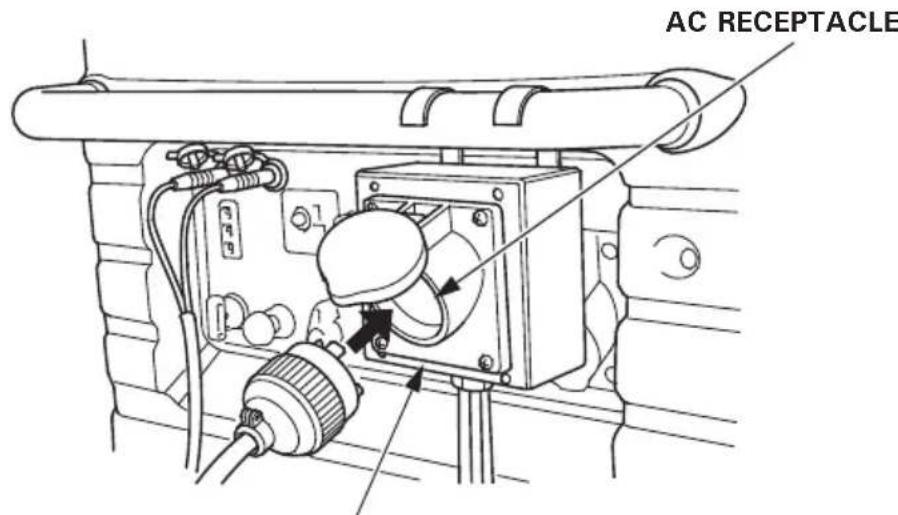
AC applications
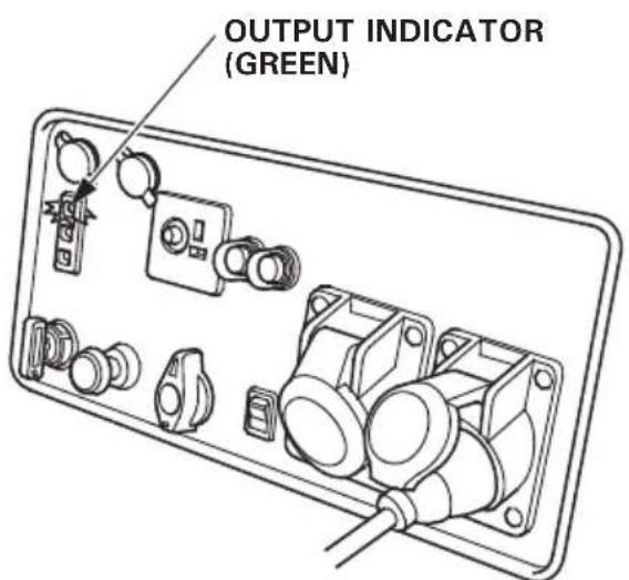
1.Start the engine and make sure the green Output indicator comes on.
2. Confirm that the appliance to be used is switched off, and plug in the appliance.
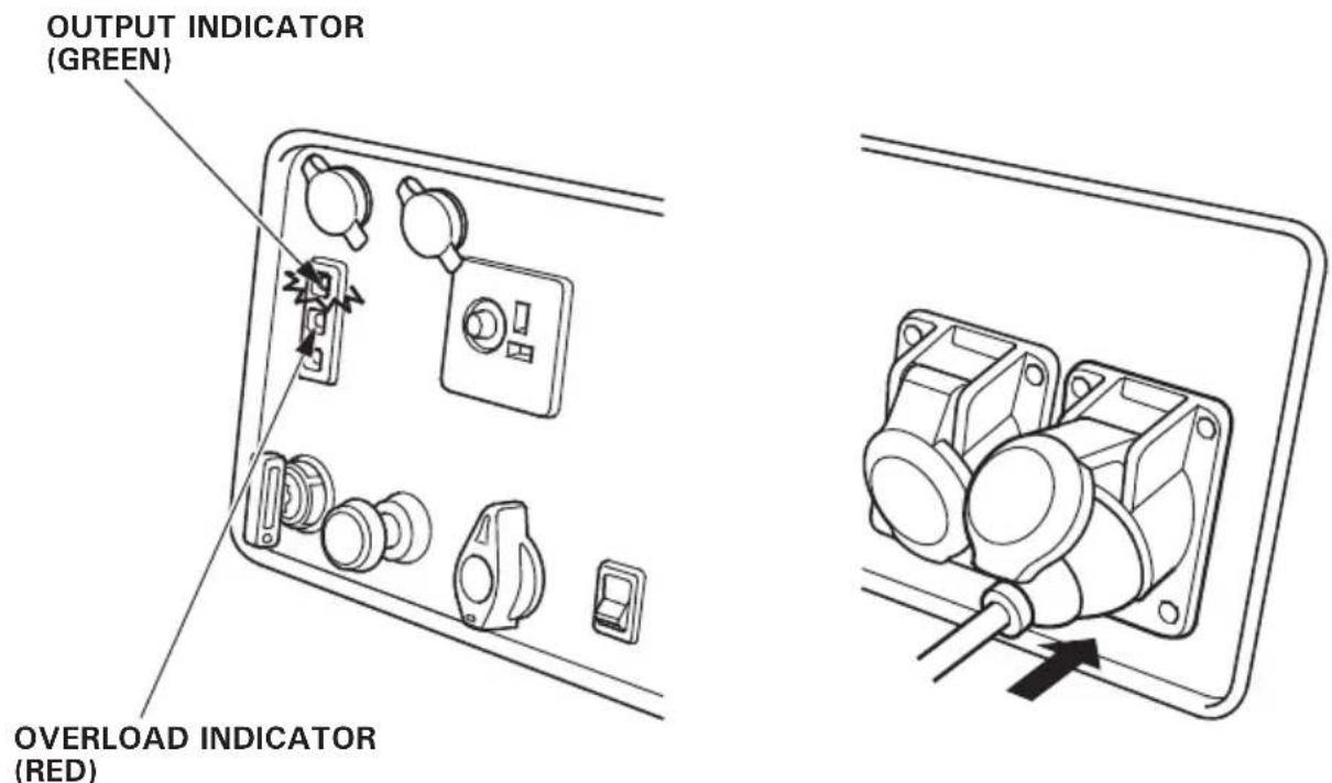
CAUTION:
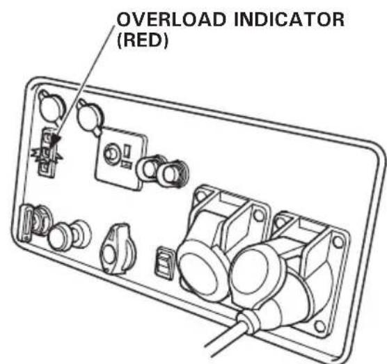
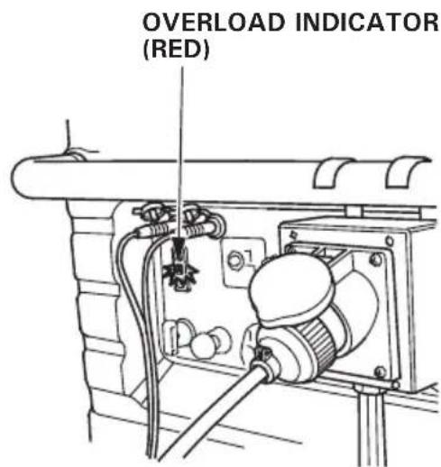
- Substantial overloading that continuously lights the Overload indicator (red) may damage the generator. Marginal overloading that temporarily lights the Overload indicator (red) may shorten the service life of the generator.
- Be sure that all appliances are in good working order before connecting them to the generator. If an appliance begins to operate abnormally, becomes sluggish, or stops suddenly, turn off the generator engine switch immediately. Then disconnect the appliance, and examine it for signs of malfunction.
AC Circuit Protector (B, F, G, GW, GW1, CL Types)
The AC circuit protectors will automatically switch OFF (push button comes out) if there is a short circuit or a significant overload of the generator at receptacle.
If an AC circuit protector switches OFF automatically, check that the appliance is working properly and does not exceed the rated load capacity of the circuit before resetting the AC circuit protector ON (pushing the push button in).

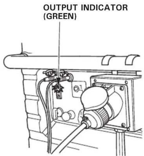
Output and Overload Indicators
The Output indicator (green) will remain on during normal operating conditions.
If the generator is overloaded (see page 30), or if there is a short in the connected appliance, the Output indicator (green) will go OFF, the overload indicator (red) will go ON and current to the connected appliance will be shut off.
Stop the engine if the Overload indicator (red) comes on and investigate the overload source.
NOTE:
The Overload indicator (red) also lights in the following cases:
- When the inverter is overheated; the current to the connected appliance will be shut off. Check to see if the air intake is obstructed.
- Before connecting an appliance to the generator, check that it is in good order, and that its electrical rating does not exceed that of the generator. Then connect the power cord of the appliance, and start the engine.
NOTE:
When an electric motor is started, both the Overload indicator (red) and the Output indicator (green) may go on simultaneously. This is normal if the Overload indicator (red) goes off after about five (5) seconds. If the Overload indicator (red) stays on, consult your Honda generator dealer.
Parallel operation
Please read the item "GENERATOR USE" before connecting any equipment to be used.
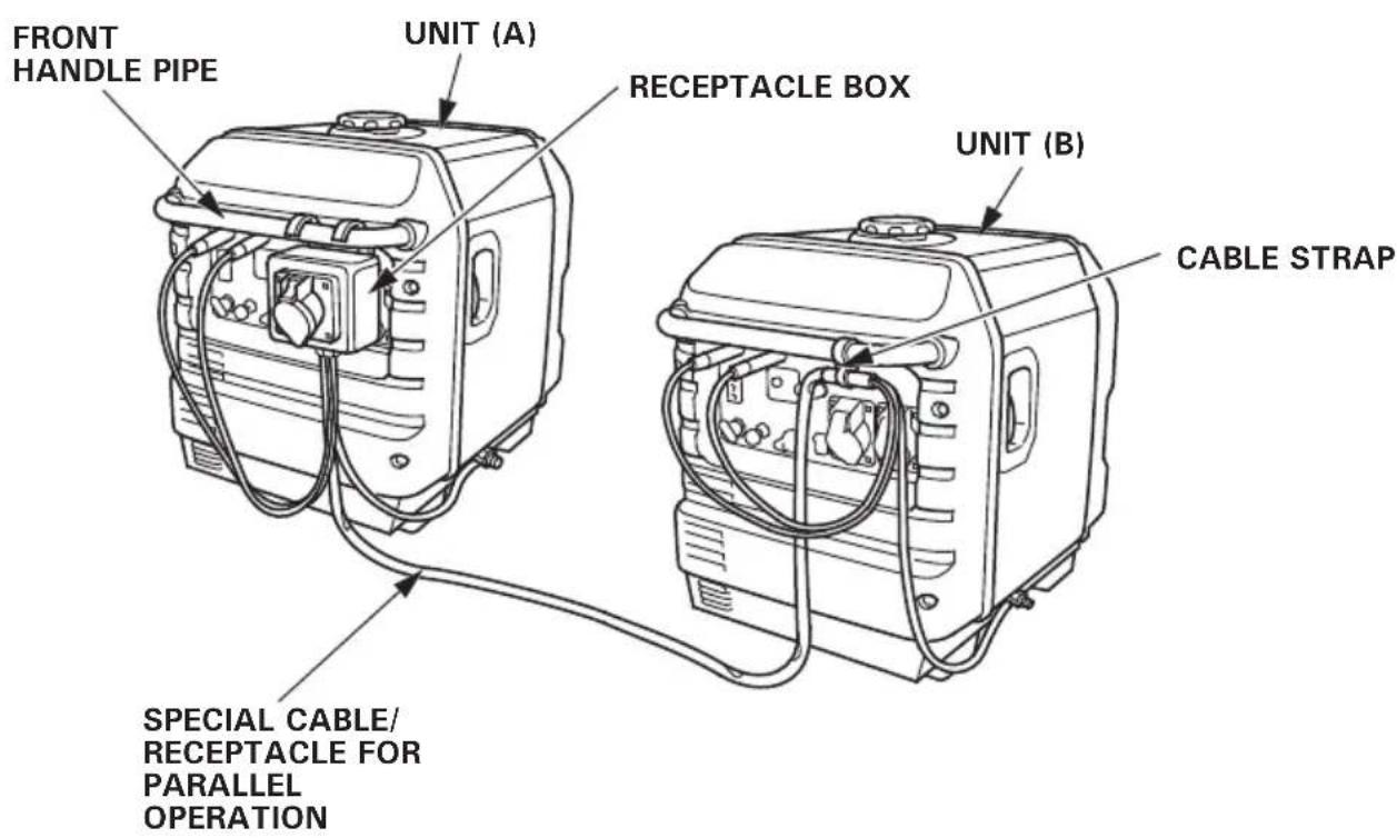
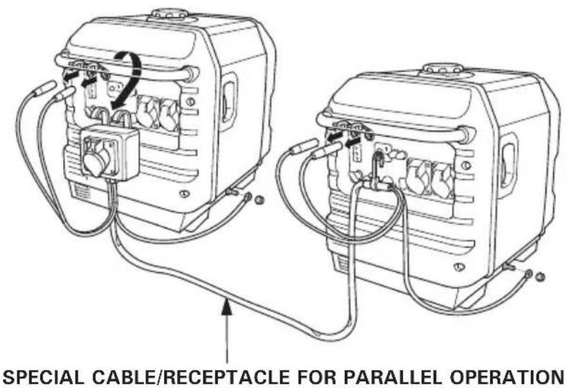
Use only a special cable/receptacle for parallel operation (sold separately).
Make sure that the electrical rating of the tool or appliance does not exceed that of the generator. Never exceed the maximum power rating of the generator. Power levels between rated and maximum may be used for no more than 30 minutes.
Limit operation requiring maximum power to 30 minutes.
Maximum power in parallel operation is:
EU26i: 5,200 VA
EU30is: 6,000 VA
For continuous operation, do not exceed the rated power.
Rated power in parallel operation is:
EU26i: 4,800 VA
EU30is: 5,600 VA
In either case, the total power requirements (VA) of all appliances connected must be considered.
CAUTION:
Substantial overloading that continuously lights the Overload indicator (red) may damage the generator. Marginal overloading that temporarily lights the Overload indicator (red) may shorten the service life of the generator.
WARNING
- Never connect the different generator models and types.
- Never connect a cable other than the special cable/receptacle for parallel operation.
- Connect and remove the special cable/receptacle for parallel operation with the engine stopped.
-
For single operation, the special cable/receptacle for parallel operation must be removed.
-
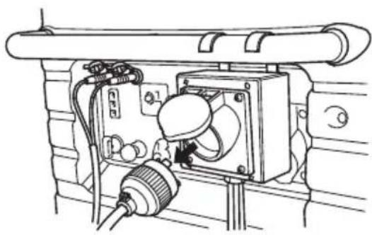
Hang the receptacle box of the special cable/receptacle on the front handle pipe of unit (A) or unit (B), and tie the longer cable of the special cable/receptacle to the front handle pipe of the other unit with the cable strap.
-
Connect the special cable/receptacle for parallel operation to the two generators.
- Be sure to ground the generator when the connected equipment is grounded.
4.Start each engine according to "STARTING THE ENGINE".
-
When the Output indicator (green) does not light and the Overload indicator (red) lights instead, set the engine switch to STOP, stop the engine once, and then start the engine again.
-
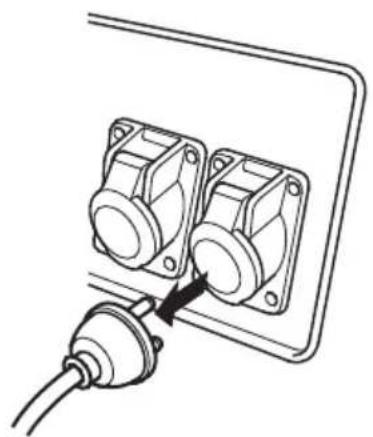
Confirm that the equipment to be used is switched off, and insert the plug of the equipment to be used into the AC receptacle of the receptacle box.
RECEPTACLE BOX
CAUTION:
Confirm that the use equipment to be connected is switched off. When the equipment to be used is switched on, it will operate suddenly, and injuries or accidents may be caused.
- Switch on the equipment to be used. The Output indicator (green) will light.
In case of normal operation In case of overload operation or short-circuit
- In case of overload operation (refer to page 33) or when trouble occurs for the equipment being used, the Output indicator (green) will go out, the Overload indicator (red) will light continuously, and no power will be put out.
At this time, the engine will not stop, so that the engine must be stopped by setting the respective engine switch to STOP.
NOTE:
-
The Overload indicator (red) also lights in the following cases: When the inverter is overheated; the current to the connected appliance will be shut off. Check to see if the air intake is obstructed.
-
When equipment requiring a large starting power, like a motor etc., is used, the Overload indicator (red) and the Output indicator (green) may light together for a short time (about 4 sec), but this is no abnormality. After start of the equipment, the Overload indicator (red) will go out and the Output indicator (green) will stay lit.
-
When the operation of one generator is to be stopped after start of the equipment, the special cable/receptacle for parallel operation also must be removed at the same time.
-
When electric power is to be taken again from the generator, switch off the equipment to be used and remove the plug from the AC receptacle. Confirm that the equipment and the connection are normal and that not too much power is to be taken, and then start the engine.
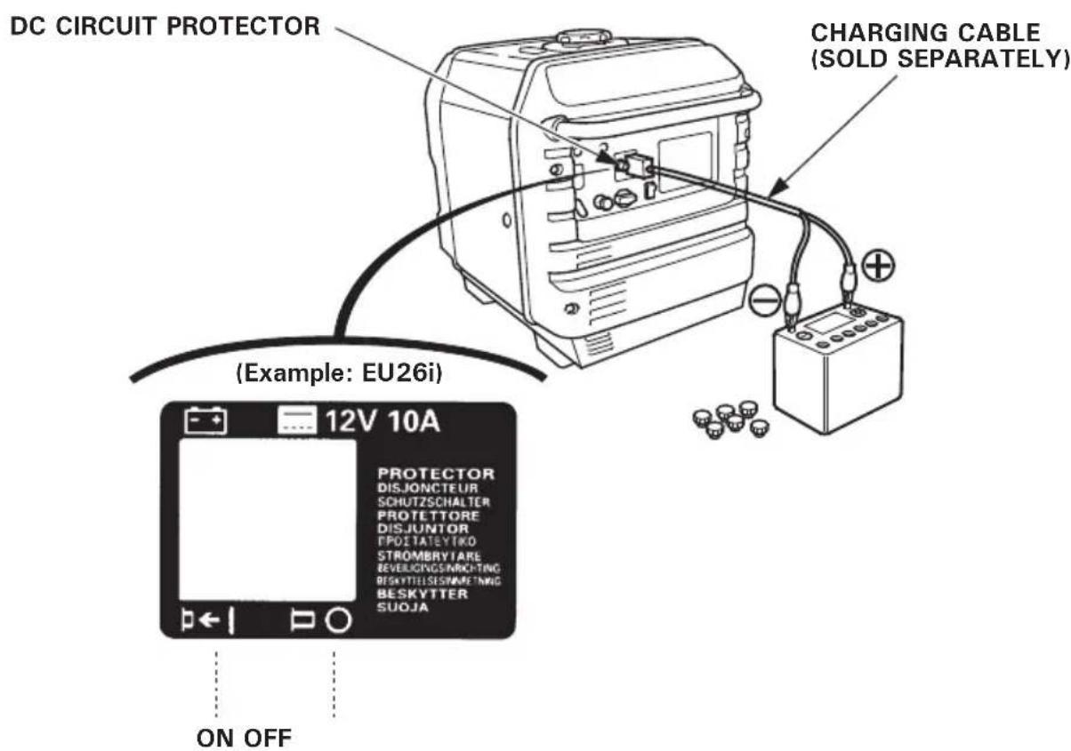
DC Application
The DC receptacle may be used for charging 12 volt automotive-type batteries only.
DC output will vary according to the position of the EcoThrottle switch. When the EcoThrottle switch is turned to the Eco position and the AC output is not used, the DC current will be about one-third of the rated current.
DC Current
| Eco throttle switch Model | OFF Eco | (do not use the AC output) |
| EU26i 10 A approximately | 3.3 A | |
| EU30is 12 A approximately | 4 A |
- Connect the charging cable to the DC receptacle of the generator and then to the battery terminals.
WARNING
- To prevent the possibility of creating a spark near the battery, connect charging cable first to the generator, then to the battery. Disconnect cable first at the battery.
- Before connecting charging cable to a battery that is installed in a vehicle, disconnect the vehicle's battery cable. Reconnect the vehicle's battery cable after the charging cables are removed. This procedure will prevent the possibility of a short circuit and sparks if you make accidental contact between a battery terminal and the vehicle's frame or body.
CAUTION:
- Do not attempt to start an automobile engine with the generator still connected to the battery. The generator may be damaged.
- Connect the positive battery terminal to the positive charging cord. Do not reverse the charging cables, or serious damage to the generator and/or battery may occur.
WARNING
- Batteries produce explosive gases: If ignited, and explosion can cause serious injury or blindness. Provide adequate ventilation when charging.
- CHEMICAL HAZARD: Battery electrolyte contains sulfuric acid. Contact with eyes or skin, even through clothing, may cause severe burns. Wear a face shield and protective clothing.
- Keep flames and sparks away, and do not smoke in the area.
ANTIDOTE: If electrolyte gets into your eyes, flush thoroughly with warm water for at least 15 minutes and call a physician immediately. -
POISON: Electrolyte is poison. ANTIDOTE
-
External: Flush thoroughly with water.
- Internal: Drink large quantities of water or milk.
Follow with milk of magnesia or vegetable oil, and call a physician immediately.
- KEEP OUT OF REACH OF CHILDREN.
2.Start the engine.
NOTE:
- The DC receptacle may be used while the AC power is in use.
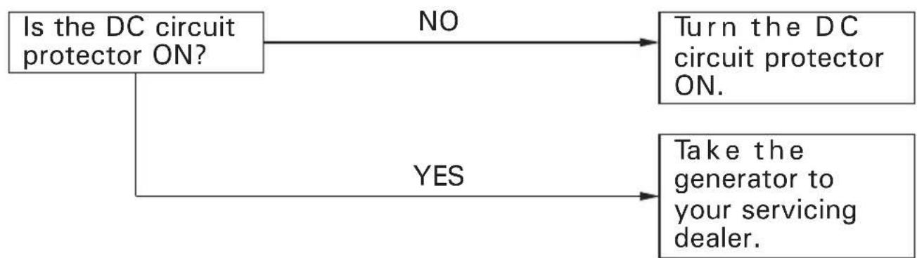
- An overload DC circuit will trip the DC circuit protector (push button comes out).
If this happens, wait a few minutes before pushing in the circuit protector to resume operation.
Oil Alert system
The Oil Alert system is designed to prevent engine damage caused by an insufficient amount of oil in the crankcase. Before the oil level in the crankcase falls below a safe limit, the Oil Alert system will automatically shut down the engine (the engine switch will remain in the ON position).
If the Oil Alert system shuts down the engine, the Oil Alert indicator (red) will come on when you operate the starter, and the engine will not run. If this occurs, add engine oil (see page 17).
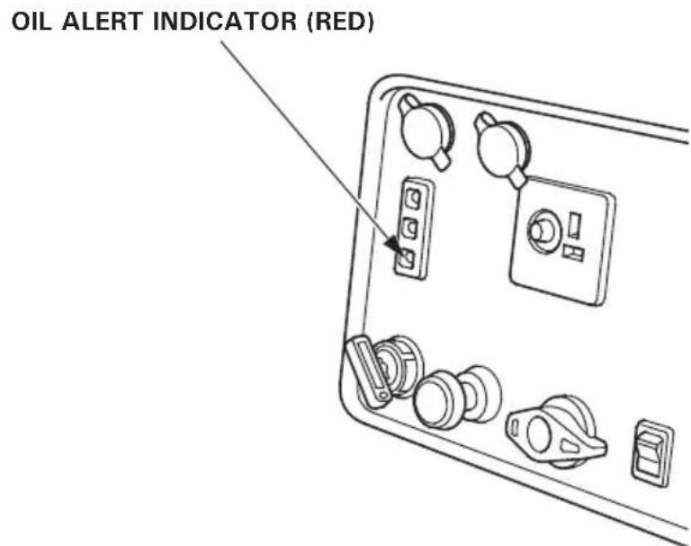
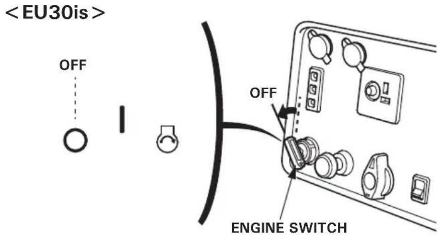
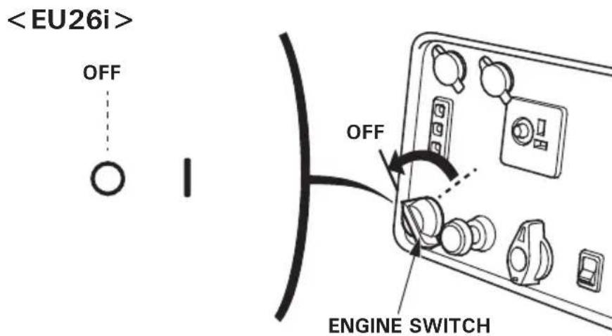
To stop the engine in an emergency, turn the engine switch to the OFF position.
IN NORMAL USE:
- Switch off the connected equipment and pull the inserted plug.
In parallel operation
- Turn the engine switch to the OFF position.
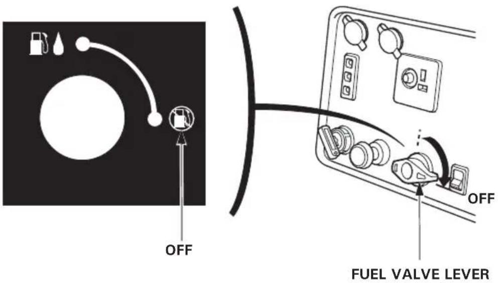
- Turn the fuel valve lever to the OFF position.
- When parallel operation has been executed, remove the special cable/ receptacle for parallel operation.
The purpose of the maintenance and adjustment schedule is to keep the generator in the best operating condition.
Inspect or service as scheduled in the table below.
WARNING
Make sure the engine is off before you begin any maintenance or repairs. This will eliminate several potential hazards:
- Carbon monoxide poisoning from engine exhaust. Be sure there is adequate ventilation whenever you operate the engine.
- Burns from hot parts. Let the engine and exhaust system cool before touching.
- Injury from moving parts. Do not run the engine unless instructed to do so.
The muffler becomes very hot during operation and remains hot for a while after stopping the engine. Be careful not to touch the muffler while it is hot. Let the engine cool before maintenance.
CAUTION:
Use Honda Genuine parts or their equivalent. The use of replacement parts which are not of equivalent quality may damage the generator.
Maintenance Schedule
| REGULAR SERVICE PERIOD (3)ItemPerformed at every indicated monthor operating hour interval,whichever comes first. | Eachuse | Firstmonthor20 hrs. | Every3 monthsor50 hrs. | Every6 monthsor100 hrs. | Everyyearor300 hrs. |
| Engine oil Check level o | |||||
| Change o o | |||||
| Air cleaner Check o | |||||
| Clean o (1) | |||||
| Replace o* | |||||
| Sediment cup Clean | o | ||||
| Spark plug Check-adjust | o | ||||
| Replace | o | ||||
| Valve Clearance Check-adjust | o (2) | ||||
| CombustionCleanchamber | After every 500 hrs. (2) | ||||
| Fuel tank & filter Clean | o (2) | ||||
| Fuel tube Check | Every 2 years (Replace if necessary) (2) | ||||
NOTE: * Replace paper element type only.
(1) Service more frequently when used in dusty areas.
(2) These items should be serviced by your servicing dealer, unless you have the proper tools and are mechanically proficient. Refer to Honda shop manual for service procedures.
(3) For commercial use, log hours of operation to determine proper maintenance intervals.
1.CHANGING OIL
Drain the oil while the engine is still warm to assure rapid and complete draining.
- Open and remove the oil maintenance cover.
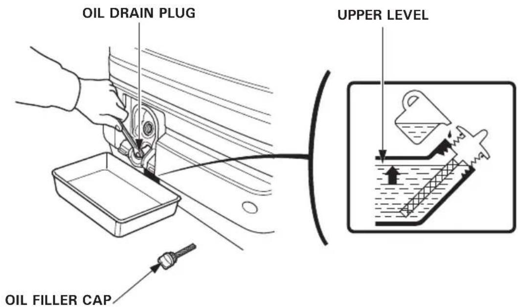
- Remove the oil filler cap and oil drain plug to drain the oil.
3.Install the oil drain plug, and tighten it securely.
4.Refill with the recommended oil (see page 16) and check the oil level.
5.Wipe off all the spilled oil from the generator.
6.Reinstall, close and latch the oil maintenance cover.
Wash your hands with soap and water after handling used oil.
NOTE:
Please dispose of used motor oil in a manner that is compatible with the environment. We suggest you take it in a sealed container to your local service station for reclamation. Do not throw it in the trash or pour it on the ground.
2.AIR CLEANER SERVICE
A dirty air cleaner will restrict air flow to the carburetor. To prevent carburetor malfunction, service the air cleaner regularly. Service more frequently when operating the generator in extremely dusty areas.
WARNING
Do not use gasoline or low flash point solvents for cleaning. They are flammable and explosive under certain conditions.
CAUTION:
Never run the generator without the air cleaner. Rapid engine wear may result.
- Open the left side maintenance cover.
2.Unsnap the clips, remove the air cleaner cover.
3.Foam element:
a. Remove the foam element from the air cleaner cover.
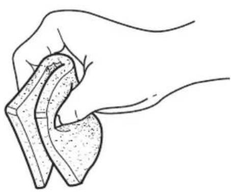
b. Wash the foam element in a solution of household detergent and warm water, then rinse thoroughly, or wash in nonflammable or high flashpoint solvent. Allow the foam element to dry thoroughly.
c. Soak the foam element in clean engine oil and squeeze out the excess oil. The engine will smoke during initial startup if too much oil is left in the foam element.
d. Reinstall the foam element to the air cleaner cover.
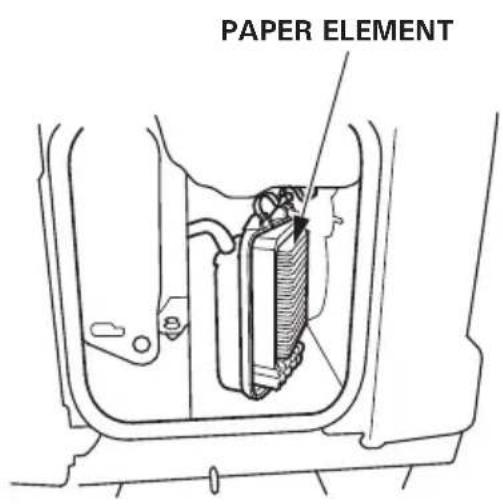
4.Paper element: If the paper element is dirty, replace it with a new one. Do not clean the paper element.
5.Reinstall the air cleaner cover. 6.Close and latch the left side maintenance cover.
3.FUEL SEDIMENT CUP SERVICE
WARNING
Gasoline is extremely flammable and is explosive under certain conditions. Do not smoke or allow flames or sparks in the area.
The filter prevents dirt or water which may be in the fuel tank from entering the carburetor. If the engine has not been run for a long time, the filter should be cleaned.
- Turn the engine switch to the STOP position.
- Turn the fuel valve lever to the OFF position.
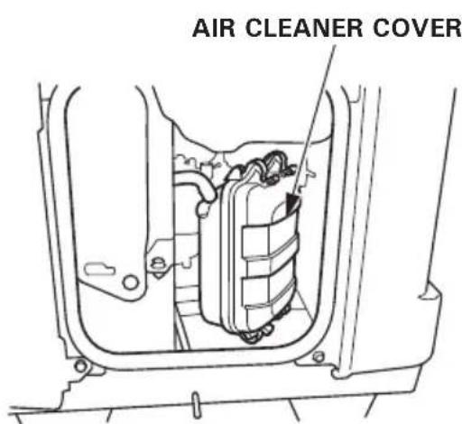
3.Open the left side maintenance cover. - Remove the air cleaner cover and paper element (see pages 45 and 46).
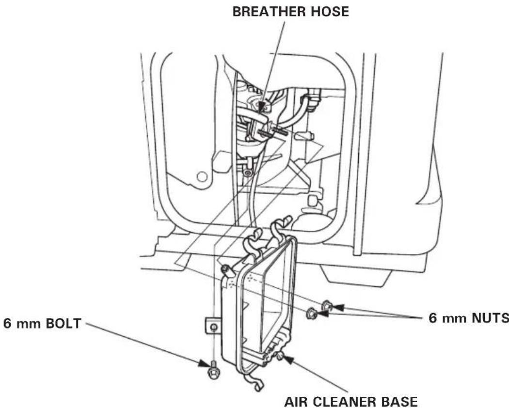
5.Disconnect the breather hose from the air cleaner base. - Remove the 6mm bolt and two 6mm nuts, and remove the air cleaner base.
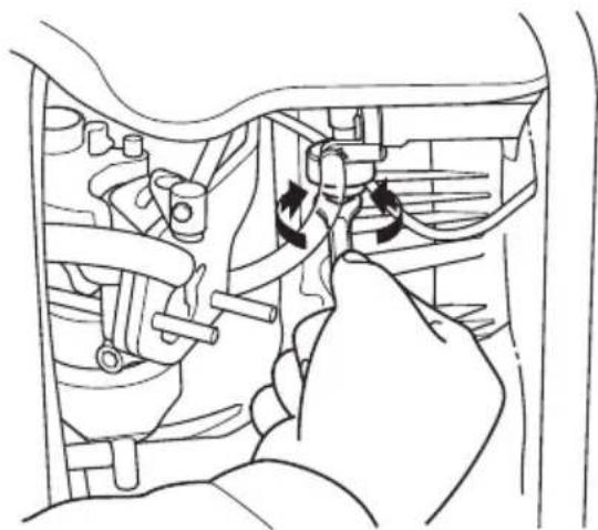
7.Remove the sediment cup by turning it counterclockwise.
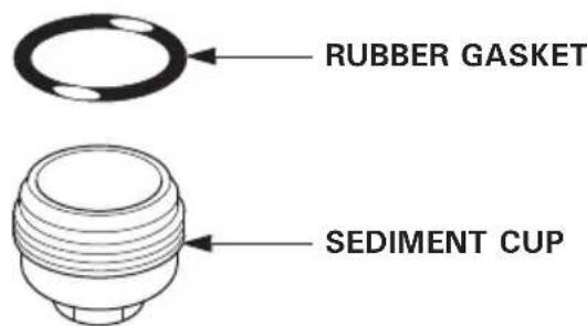
8. Clean the sediment cup, rubber gasket in nonflammable or high flash point solvent.
9. Reassemble the rubber gasket, and sediment cup. Tighten securely.
10. Reinstall the air cleaner base, and connect the breather gas hose with the air cleaner base.
11. Reinstall the paper element and air cleaner cover.
12.Close and latch the left side maintenance cover.
WARNING
After installing the sediment cup, be sure to tighten it securely. Check for fuel leaks and make sure the area is dry before starting the engine.
4.SPARK PLUG SERVICE
RECOMMENDED SPARK PLUG:
EU26i: BPR5ES (NGK), W16EPR-U (DENSO)
EU30is: BPR6ES (NGK), W20EPR-U (DENSO)
To ensure proper engine operation, the spark plug must be properly gapped and free of deposits.
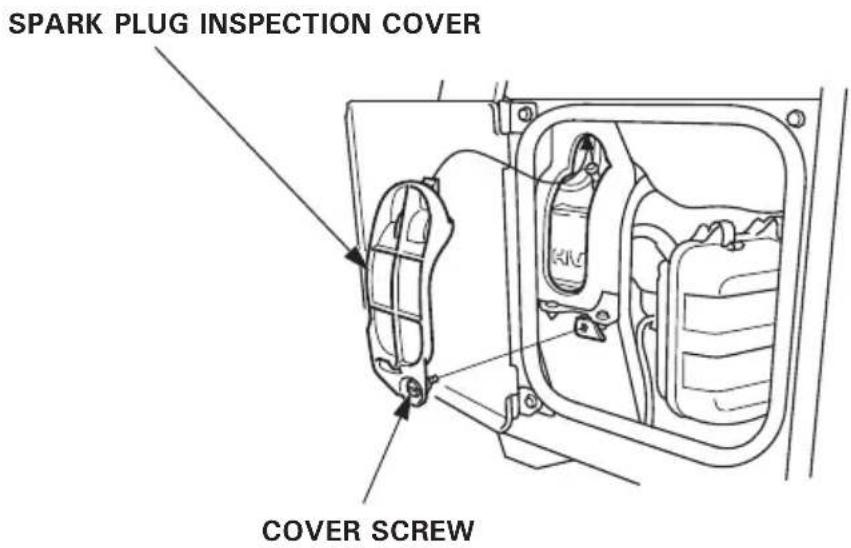
- Open the left side maintenance cover.
- Loosen the cover screw and remove the spark plug inspection cover.
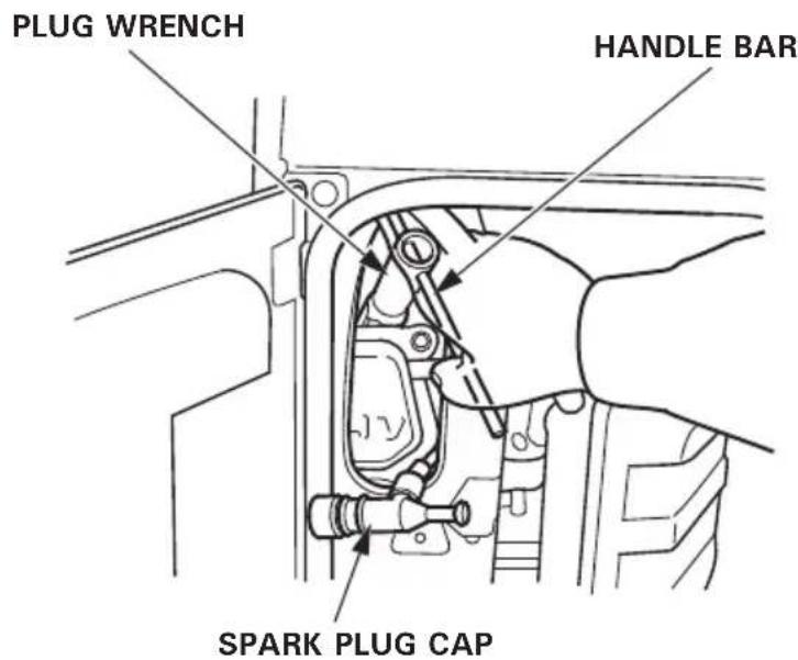
3.Remove the spark plug cap.
4.Clean any dirt from around the spark plug base.
5.Use a spark plug wrench to remove the spark plug.
- Visually inspect the spark plug. Discard it if the insulator is cracked, chipped, or fouled. Clean the spark plug with a wire brush if it is to be reused.
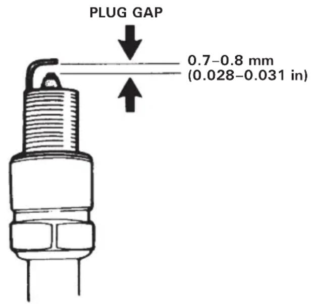
7.Measure the plug gap with a feeler gauge. Correct as necessary by carefully bending the side electrode. The gap should be: 0.7-0.8 mm (0.028-0.031 in)
8.Install the spark plug carefully by hand, to avoid cross-threading.
9. After a new spark plug has been seated by hand, it should be tightened 1/2 turn with a wrench to compress its washer. If a used plug is being reinstalled, it should only require 1/8 to 1/4 turn after being seated.
10. Reinstall the spark plug inspection cover and tighten the cover screw.
11. Close and latch the left side maintenance cover.
CAUTION:
- The spark plug must be securely tightened. An improperly tightened plug can become very hot and possibly damage the generator.
- Never use a spark plug with an improper heat range.
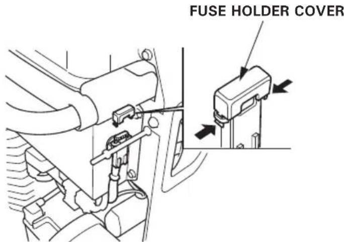
5.FUSE REPLACEMENT
(EU30is only)
If the fuse is blown, the starter motor will not work until it is replaced.
- Turn the engine switch to the OFF position.
2.Remove the four 6mm cap nuts and the front cover.
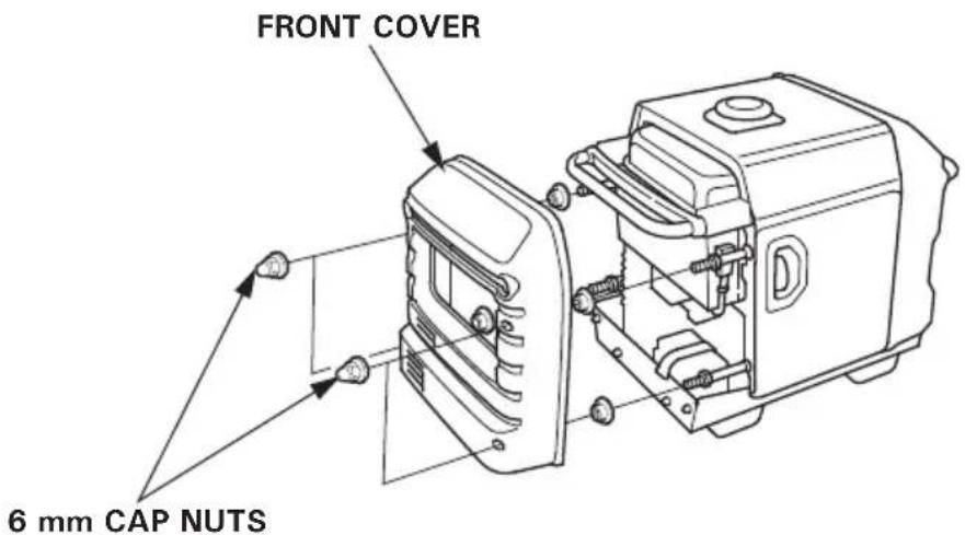
3.Remove the fuse holder cover and replace the fuse.
Specified fuse: 5 A
CAUTION:
- If frequent fuse failure occurs, determine the cause and correct the problem before attempting to operate the generator further.
- Never use a fuse with a different rating from that specified. Serious damage to the electrical system or fire may result.
6.BATTERY REMOVAL/INSTALLATION
(EU30is only)
WARNING
- Batteries produce explosive gases: If ignited, and explosion can cause serious injury or blindness. Provide adequate ventilation when charging.
- CHEMICAL HAZARD: Battery electrolyte contains sulfuric acid. Contact with eyes or skin, even through clothing, may cause severe burns. Wear a face shield and protective clothing.
- Keep flames and sparks away, and do not smoke in the area. ANTIDOTE: If electrolyte gets into your eyes, flush thoroughly with warm water for at least 15 minutes and call a physician immediately.
-
POISON: Electrolyte is poison. ANTIDOTE
-
External: Flush thoroughly with water.
- Internal: Drink large quantities of water or milk.
Follow with milk of magnesia or vegetable oil, and call a physician immediately.
- KEEP OUT OF REACH OF CHILDREN.
Removal:
- Turn the engine switch to the OFF position.
2.Remove the four 6 mm cap nuts and the front cover. (see page 51)
3.Remove the battery holder band.
4.Disconnect the battery cable at the battery negative (-) terminal, then at the battery positive (+) terminal.
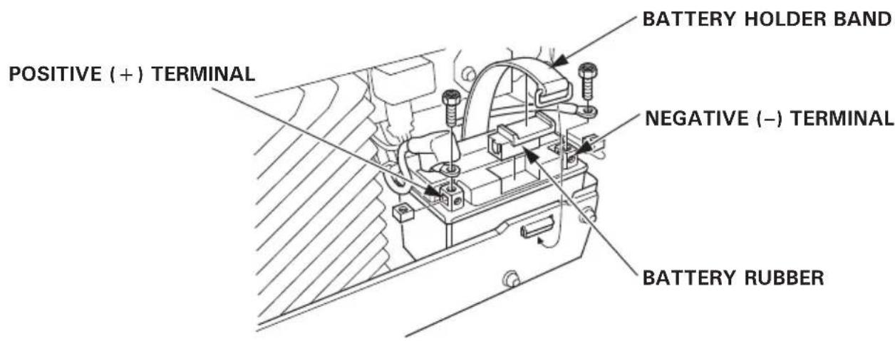
5.Remove the battery and the battery rubber from the battery tray.
Installation:
1.Make sure that the engine switch is turned OFF.
2. Connect the battery positive (+) cable to the battery positive (+) terminal, then the battery negative (-) cable to the battery negative (-) terminal. Tighten the bolts and nuts securely.
3.Install the battery holder band.
4.Install the front cover, and install the four 6 mm cap nuts.
CAUTION:
When disconnecting the battery cable, be sure to disconnect at the battery negative (-) terminal first. To connect, connect at the positive (+) terminal first, then at the negative (-) terminal. Never dis/connect the battery cable in the reverse order, or it causes a short circuit when a tool contacts the terminals.
This symbol on the battery means that this product must not be treated as household waste.
NOTE:
An improperly disposed of battery can be harmful to the environment and human health.
Always confirm local regulations for battery disposal.
To prevent fuel spillage when transporting or during temporary storage, the generator should be secured upright in its normal operating position, with the engine switch OFF.
The fuel valve lever should be turned OFF.
WARNING
When transporting the generator:
- Do not overfill the tank.
- Do not operate the generator while it is on a vehicle. Take the generator off the vehicle and use it in a well ventilated place.
- Avoid a place exposed to direct sunlight when putting the generator on a vehicle. If the generator is left in an enclosed vehicle for many hours, high temperature inside the vehicle could cause fuel to vaporize resulting in a possible explosion.
- Do not drive on a rough road for an extended period with the generator on board. If you must transport the generator on a rough road, drain the fuel from the generator beforehand.
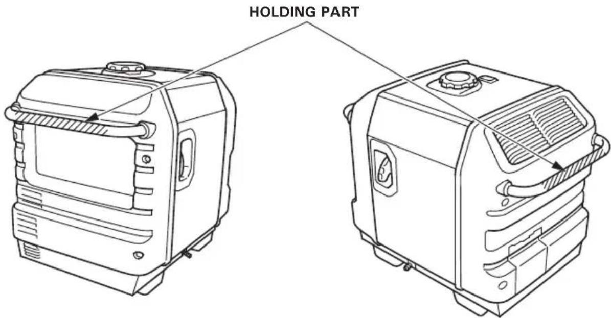
NOTE:
To lift up the generator, hold the holding part (shaded areas in the figure below) with your assistants.
According to EUROPEAN STANDARD EN 12601: 2010
Carrying the generating set is considered that a 140kg set should be provided with the means of carrying by 4 persons.
Before storing the unit for an extended period:
1.Be sure the storage area is free of excessive humidity and dust.
2.Drain the fuel.
WARNING
Gasoline is extremely flammable and is explosive under certain conditions. Perform this task in a well ventilated area with the engine stopped. Do not smoke or allow flames or sparks in the area during this procedure.
a. Open the left side maintenance cover.
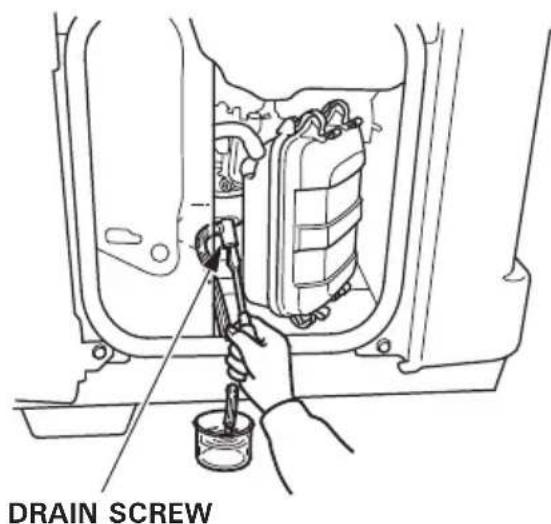
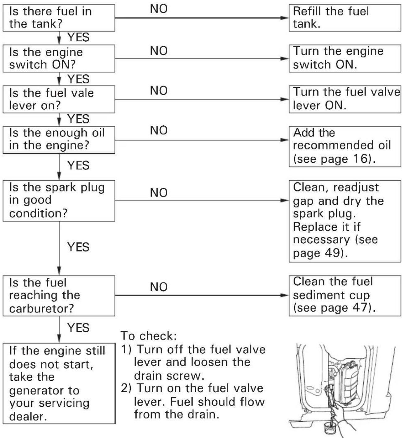
b. Turn fuel valve lever to ON and then loosen the carburetor drain screw. Drain the gasoline from the carburetor and fuel tank into a suitable container.
c. Tighten the carburetor drain screw, turn the fuel valve lever to OFF and close the left side maintenance cover.
3.Once a month, recharge the battery. (EU30is only)
4. Change the engine oil.
5. Remove the spark plug and pour about a tablespoon of clean engine oil into the cylinder. Crank the engine several revolutions to distribute the oil, then reinstall the spark plug.
6. Slowly pull the starter grip until resistance is felt. At this point, the piston is coming up on its compression stroke and both the intake and exhaust valves are closed. Storing the engine in this position will help to protect it from internal corrosion.
When the engine will not start:
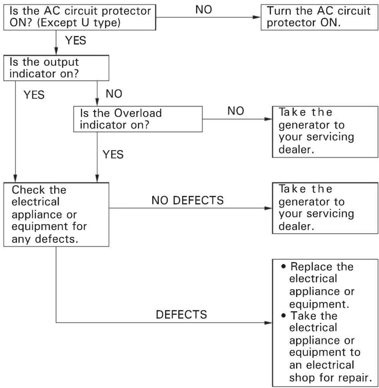
Appliance does not operate:
No electricity at the DC receptacle:
Dimensions and Weight
| Model EU26i | |
| Description code EZGE | |
| Length (Stand type) 658 mm (25.9 in) (Wheel type) 658 mm (25.9 in) | |
| Width (Stand type) 447 mm (17.6 in) (Wheel type) 482 mm (19.0 in) | |
| Height (Stand type) 558 mm (22.0 in) (Wheel type) 570 mm (22.4 in) | |
| Dry mass (weight) (Stand type) 53.7 kg (118.4 lbs) (Wheel type) 55.9 kg (123.2 lbs) |
Engine
| Model GX160 | |
| Engine type 4-stroke, overhead valve, single cylinder | |
| Displacement | 163 cm³ (9.9 cu-in) |
| Bore × Stroke 68.0 × 45.0 mm (2.6 × 1.77 in) | |
| Compression ratio 9.0:1 | |
| Engine speed | 2,500–3,800 rpm 3,500–3,800 rpm (with eco throttle OFF) |
| Cooling system | Forced air |
| Ignition system | Transistor magneto |
| Oil capacity | 0.53 L (0.56 US qt, 0.47 Imp qt) |
| Fuel tank capacity | 13.0 L (3.43 US gal, 2.86 Imp gal) |
| Spark plug | BPR5ES (NGK) W16EPR-U (DENSO) |
Generator
| Model EU26i | |
| Type | F, G, GW, B |
| AC output Rated Voltage (V) | 230 |
| 50 | |
| 10.5 | |
| 2.4 | |
| 2.6 | |
| DC rated output | Only for charging 12 V automotive batteries. 12 V, 10 A |
Noise
| Model EU26i | |
| Type F, G, GW, B | |
| Sound pressure level at the workstation (2006/42/EC) | 73 dB (A) |
| Microphone point Center CONTROL PANEL 1.60 m | |
| Uncertainty 2 dB (A) | |
| Measured sound power level (2000/14/EC, 2005/88/EC) | 88 dB (A) |
| Uncertainty 2 dB (A) | |
| Guaranteed sound power level (2000/14/EC, 2005/88/EC) | 90 dB (A) |
"the figures quoted are emission levels and are not necessarily safe working levels. Whilst there is a correlation between the emission and exposure levels, this cannot be used reliably to determine whether or not further precautions are required. Factors that influence the actual level of exposure of work-force include the characteristics of the work room, the other sources of noise, etc. i.e. the number of machines and other adjacent processes, and the length of time for which an operator is exposed to the noise. Also the permissible exposure level can vary from country. This information, however, will enable the user of the machine to make a better evaluation of the hazard and risk".
NOTE:
Specifications are subject to change without notice.
Dimensions and Weight
| Model EU30is | |
| Description code EZGF | |
| Length (Stand type) 658 mm (25.9 in) (Wheel type) 6 | 58 mm (25.9 in) |
| Width (Stand type) 447 mm (17.6 in) (Wheel type) 4 | 82 mm (19.0 in) |
| Height (Stand type) 558 mm (22.0 in) (Wheel type) 5 | 70 mm (22.4 in) |
| Dry mass (weight) (Stand type) 59.0 kg (130.1 lbs) (Wheel type) 6 | 1.2 kg (134.9 lbs) |
Engine
| Model GX200 | |
| Engine type 4-stroke, overhead valve, single cylinder | |
| Displacement | 196 cm³ (12.0 cu-in) |
| Bore × Stroke 68.0 × 54.0 mm (2.68 × 2.13 in) | |
| Compression ratio 8.5:1 | |
| Engine speed 2,500–3,800 rpm | 3,500–3,800 rpm (with eco throttle OFF) |
| Cooling system Forced air | |
| Ignition system | Transistor magneto |
| Oil capacity | 0.55 L (0.58 US qt, 0.48 Imp qt) |
| Fuel tank capacity | 13.0 L (3.43 US gal, 2.86 Imp gal) |
| Spark plug | BPR6ES (NGK) W20EPR-U (DENSO) |
| Battery | 12 V 8.6 Ah/10 HR |
Generator
| Model EU30is | ||
| Type | F, G, GW, GW1, B, CL | U |
| AC output | Rated Voltage (V) 230 | 240 |
| Rated Frequency (Hz) | 50 | |
| Rated Ampere (A) | 12.2 | |
| Rated Output (kVA) | 2.8 | |
| Max Output (kVA) | 3.0 | |
| DC rated output | Only for charging 12 V automotive batteries. 12 V, 12 A | |
Noise
| Model EU30is | ||
| Type F, G, GW, GW1, B, CL U | ||
| Sound pressure level at the workstation (2006/42/EC) | 74 dB (A) - | |
| Microphone point Center CONTROL PANEL 1.60 m | ||
| Uncertainty 2 dB (A) | - | |
| Measured sound power level (2000/14/EC, 2005/88/EC) | 89 dB (A) - | |
| Uncertainty 2 dB (A) | - | |
| Guaranteed sound power level (2000/14/EC, 2005/88/EC) | 91 dB (A) - | |
"the figures quoted are emission levels and are not necessarily safe working levels. Whilst there is a correlation between the emission and exposure levels, this cannot be used reliably to determine whether or not further precautions are required. Factors that influence the actual level of exposure of work-force include the characteristics of the work room, the other sources of noise, etc. i.e. the number of machines and other adjacent processes, and the length of time for which an operator is exposed to the noise. Also the permissible exposure level can vary from country. This information, however, will enable the user of the machine to make a better evaluation of the hazard and risk".
NOTE:
Specifications are subject to change without notice.
INDEX
(See inside back cover)
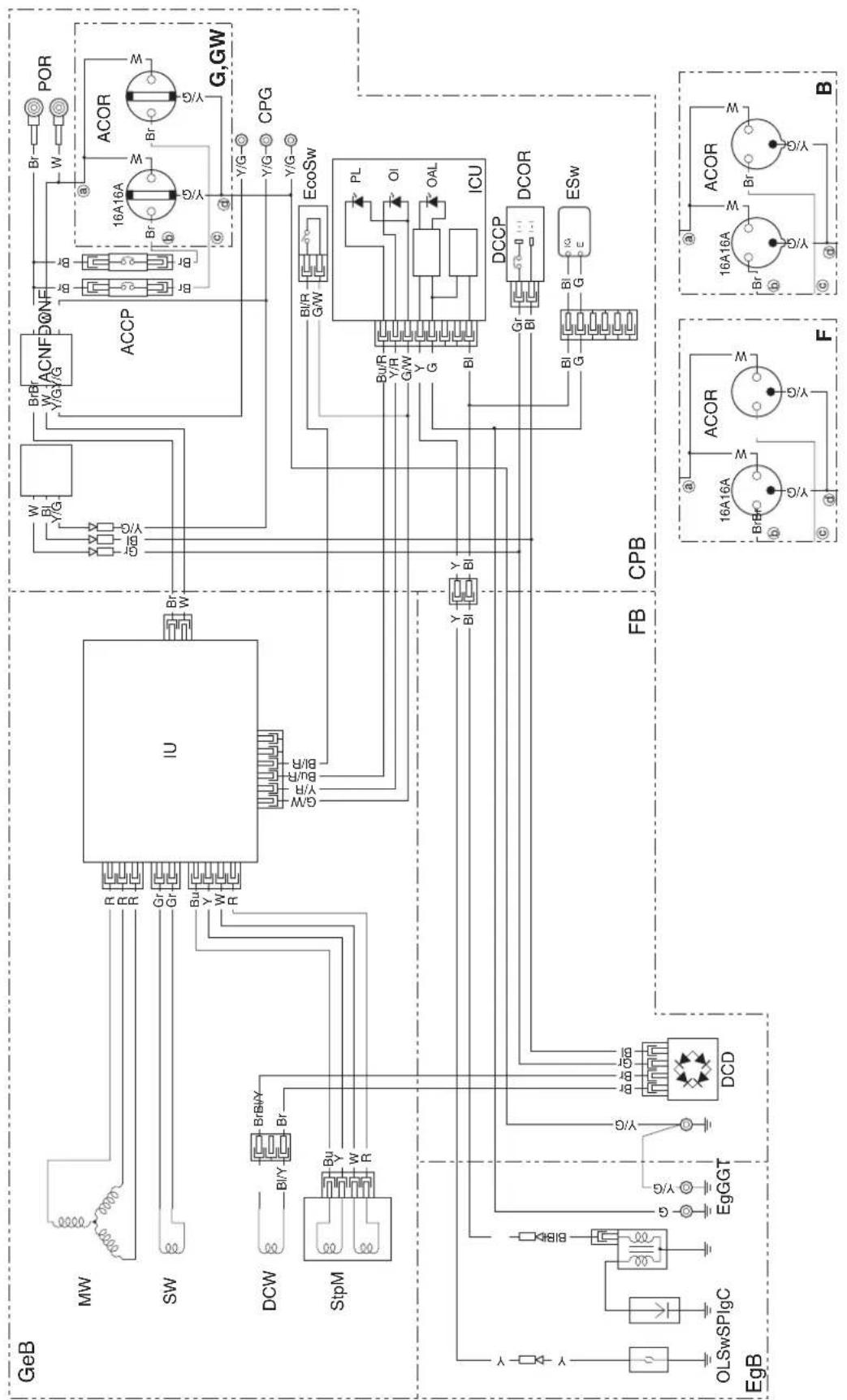
EU26i: G, GW, B, F types W-1
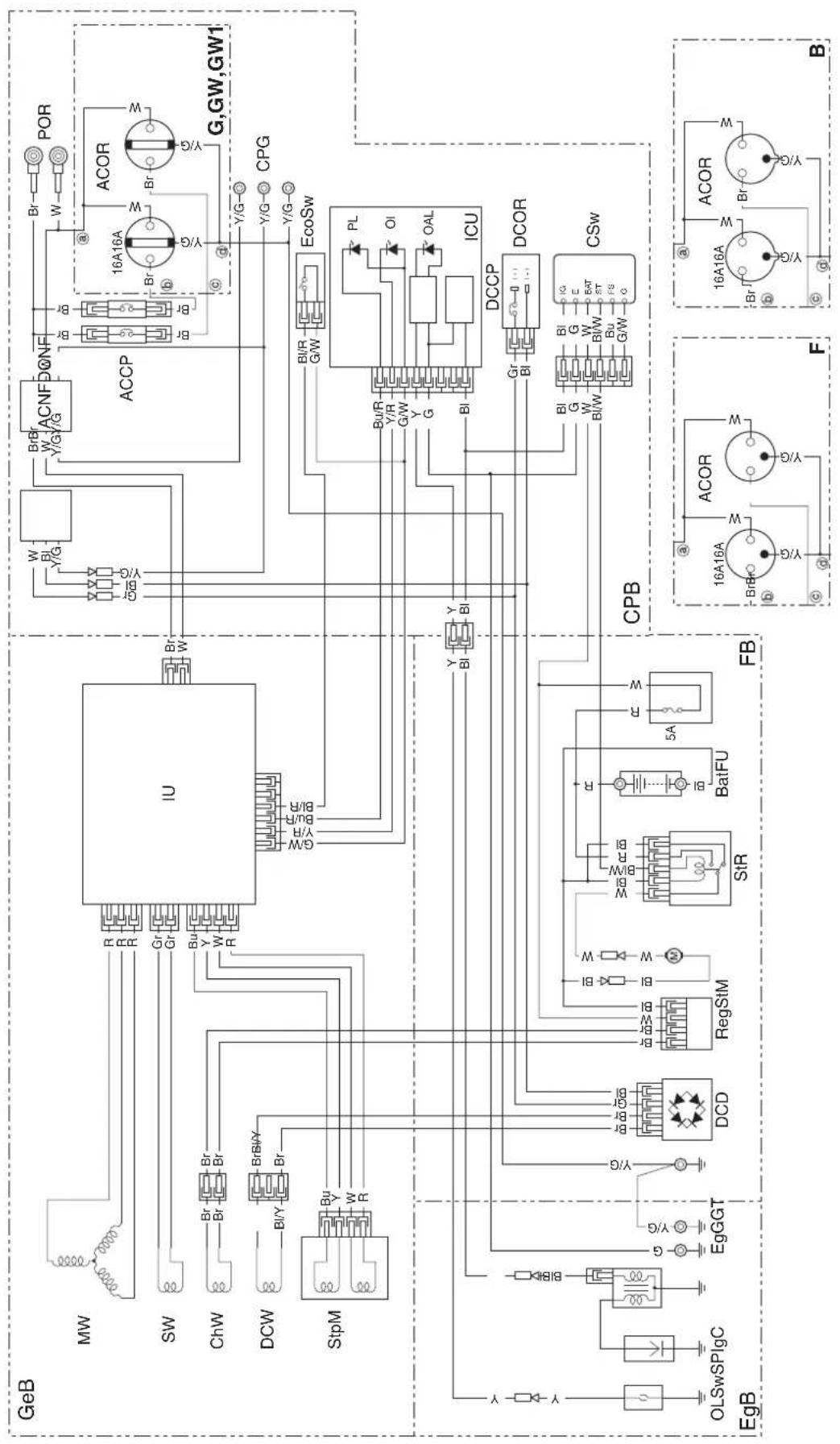
EU30is: G, GW, GW1, B, F, CL types W-2
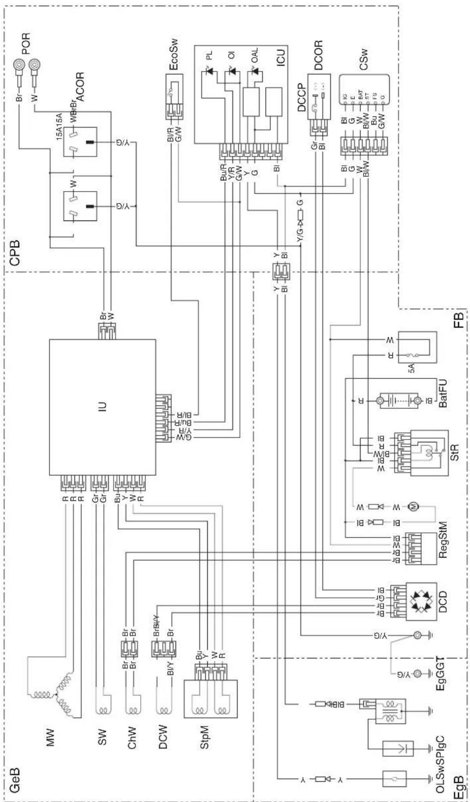
EU30is: U type. W-3
ABBREVIATIONS
Symbol Part name
ACCP AC Circuit Protector
ACNF AC Noise Filter
ACOR AC Output Receptacle
Bat Battery
ChW Charge Winding
CPB Control Panel Block
CPG Control Panel Ground
CSw Combination Switch
DCCP DC Circuit Protector
DCD DC Diode
DCNF DC Noise Filter
DCOR DC Output Receptacle
DCW DC Winding
EcoSw Eco Throttle Switch
EgB Engine Block
EgG Engine Ground
ESw Engine Switch
FB Frame Block
FU Fuse
GeB Generator Block
GT Ground Terminal
ICU Ignition Control Unit
IgC Ignition Coil
IU Inverter Unit
MW Main Winding
OAL Oil Alert Indicator
OI Overload Indicator
OLSw Oil Level Switch
Symbol Part name
PL Output Indicator
POR Parallel Operation
Receptacle
Reg Regulator
SP Spark Plug
StM Starter Motor
StpM Stepping Motor
StR Starter Relay
SW Sub Winding
WIRE COLOR CODE
BI BLACK
Y YELLOW
Bu BLUE
G GREEN
R RED
W WHITE
Br BROWN
Lg LIGHT GREEN
Gr GRAY
Lb LIGHT BLUE
ORANGE
P PINK
SWITCH CONNECTIONS
ENGINE SWITCH
EU26i
| IG | E | |
| OFF o o | — | — |
| ON |
COMBINATION SWITCH
EU30is
| IG E | BAT S | T FS G | ||||
| O F F | — | — 0 | 0 | 0 | — 0 | |
| ON | ||||||
| START o o | — — |
ECO THROTTLE SWITCH
| BI/R G/W | ECO THROTTLE | |
| ON | 0-0 | OFF |
| OFF | ON |
RECEPTACLE
| Type Shape Plug | |||
| G, GW, CL | GROUND PIN | ||
| GW1 | GROUND PIN | ||
| B | GROUND PIN | ||
| F | GROUND PIN | ||
| U | GROUND PIN | ||
WIRINGDIAGRAM
SCHEMADECABLAGE
SCHALTPLAN
DIAGRAMADECONEXIONES
MAJOR Honda DISTRIBUTOR ADDRESSES
For further information, please contact Honda Customer Information Centre at the following address or telephone number:
BALTIC STATES (Estonia/Latvia/ Lithuania)
Honda Motor Europe Ltd.
Estonian Branch
Tulika 15/17
10613 Tallinn
Tel.:+3726801300
Fax: +372 6801 301

honda.baltic@honda-eu.com.
BELGIUM
Honda Belgium
Doornveld 180-184
1731 Zellik
Te1.:+3226201000
Fax: +32 2620 10 01
http://www.honda.be

BH_PE@HONDA-EU.COM
BULGARIA
Kirov Ltd.
49 Tsaritsa Yoana blvd 1324 Sofia
Tel. : +359 2 93 30 892
Fax: +359 2 93 30 814
http://www.kirov.net

honda@kirov.net
CROATIA
Hongoldonia d.o.o.
Jelkovecka Cesta 5
10360 Sesvete - Zagreb
Tel. +38512002053
Fax:+38512020754
http://www.hongoldonia.hr

jure@hongoldonia.hr
CYPRUS
Alexander Dimitriou & Sons Ltd.
162, Yiannos Kranidiotis Avenue
2235 Latsia, Nicosia
TeI. +35722715300
Fax: +357 22 715 400
CZECH REPUBLIC
BG Technik cs, a.s.
U Zavodiste 251/8
15900 Prague 5 - Velka Chuchle
Tel. : + 420283870850
Fax: +420 2667 111 45
http://www.honda-stroje.cz
DENMARK
Tima Products A/S
Tarnfalkvej 16 2650 Hvidovre
Te1.:+4536342550
Fax: +45 36 77 16 30
http://www.tima.dk
FINLAND
OY Brandt AB.
Tuupakantie 7B
01740 Vantaa
Tel. : + 358207757200
Fax: +358 9 878 5276
http://www.brandt.fi
FRANCE
Honda Relations Clients TSA 80627
45146 St Jean de la Ruelle Cedex
Tel.:0238813390
Fax:0238813391
http://www.honda-fr.com

espaceclient@honda-eu.com
GERMANY
M50 Business Park, Ballymount Dublin 12
Tel.:+35314381900
Fax: +353 1 4607851
http://www.hondaireland.ie

Service@hondaireland.ie
ITALY
The Associated Motors
Company Ltd.
New Street in San Gwakkin Road
Afd, Power Equipment
Capronilaan 1
1119 NN Schiphol-Rijk
Tel. +31 2070000
Fax: +31 20 7070001
http://www.honda.nl
NORWAY
Berema AS
P.O.Box 454 1401 Ski
Tel. +4764860500
Fax: +47 64 86 05 49
http://www.berema.no

berema@berema.no
POLAND
Aries Power Equipment Sp. z o.o.
- MKAD 47 km., Leninsky district.
Moscow region, 142784 Russia
Tel.:+7(495)7452080
Fax: +7 (495) 745 2081
http://www.honda.co.ru

postoffice@honda.co.ru
SERBIA & MONTENEGRO
Bazis Grupa d.o.o.
Grcica Milenko 39
11000 Belgrade
Tel.: +381 11 3820 295
Fax: +381 11 3820 296
http://www.hondasrbija.co.rs
SLOVAKIA REPUBLIC
Honda Slovakia, spel. s r.o.
Prievozská 6 821 09 Bratislava
Tel. :+421 232131112
Fax: +421 232131111
http://www.honda.sk
SLOVENIA
AS Domzale Moto Center D.O.O.
Blatnica 3A
1236Trzin
Tel. : +386 1562 22 42
Fax: +386 1562 37 05
http://www.as-domzale-motoc.si
SPAIN &
Las Palmas province
(Canary Islands)
Greens Power Products, S.L.
Poligono Industrial Congost -
Av Ramon Ciurans n^2
08530 La Garriga - Barcelona
Tel.: +34 93 860 50 25
Fax: +34 93 871 81 80
http://www.hondaencasa.com
Tenerife province
(Canary Islands)
Honda (UK) Power Equipment
470 London Road
Slough - Berkshire, SL3 8QY
Te1. +44 (0)845 200 8000
http://www.honda.co.uk
AUSTRALIA
Honda Australia Motorcycle and
Power Equipment Pty. Ltd
1954-1956 Hume Highway
Campbellfield Victoria 3061
Tel.: (03) 9270 1111
Fax:(03)92701133
CHILE
Honda Motor De Chile S.A
San Ignacio 031 Quilicura
Cod. Postal 8720018-Santiago
Tel.:+5622709800
Fax: +56 2 7386511
http://www.honda.cl

contacto@honda.cl
"EC Declaration of Conformity" CONTENT OUTLINE "CE-Déclaration de conformité" DESCRIPTION DE TABLE DES MATIERES "EU-Konformitätserklärung" INHALTSÜBERSICHT DESCRIPTION GENERAL DEL CONTENIDO DE LA "Declaración de Conformidad CE" DESCrizIONE DEL CONTENO DELLA "Dichiarazione CE di Conformità"
EC Declaration of Conformity
-
The undersigned, Piet Renneboog, on behalf of the authorized representative, herewith declares that the machinery described below fulfils all the relevant provisions of:
-
Directive 2006/42/EC on machinery
- Directive 2004/108/EC on electromagnetic compatibility
-
Directive 2000/14/EC - 2005/88/EC on outdoor noise
-
Description of the machinery
a) Generic denomination: Generating sets
b) Function: producing electrical power
c) Commercial name d) Type e) Serial number
*1 *1
- Manufacturer
Honda Motor Co., Ltd.
2-1-1 Minamiaoyama
Minato-ku, Tokyo, JAPAN
- Authorized representative
Honda Motor Europe Ltd. Aalst Office
- References to harmonized standards 6. Other standards or specifications
EN 12601:2010 -
- Outdoor noise Directive
a) Measured sound power dB(A): *1
b) Guaranteed sound power dB(A):
c) Noise parameter:
d) Conformity assessment procedure:
e) Notified body:
- Done at:
- Date:
*1
*1
ANNEX VI
AIB-VINCOTTE International NV
Homologation Manager
Honda Motor Europe, Ltd., Aalst Office
Types G, GW, GW1, B, F, CL

Types G, GW, GW1, B, F, CL
For further information, please contact Honda Customer Information Centre at the following address or telephone number:
BALTIC STATES (Estonia/Latvia/ Lithuania)
Honda Motor Europe Ltd.
Estonian Branch
Tulika 15/17
10613 Tallinn
Tel.:+3726801300
Fax: +372 6801 301

honda.baltic@honda-eu.com.
BELGIUM
Honda Belgium
Doornveld 180-184
1731 Zellik
Te1.:+3226201000
Fax: +32 2620 10 01
http://www.honda.be

BH_PE@HONDA-EU.COM
BULGARIA
Kirov Ltd.
49 Tsaritsa Yoana blvd 1324 Sofia
Tel. : +359 2 93 30 892
Fax: +359 2 93 30 814
http://www.kirov.net

honda@kirov.net
CROATIA
Hongoldonia d.o.o.
Jelkovecka Cesta 5
10360 Sesvete - Zagreb
Tel. +38512002053
Fax: +385 1 2020754
http://www.hongoldonia.hr

jure@hongoldonia.hr
CYPRUS
Alexander Dimitriou & Sons Ltd.
162, Yiannos Kranidiotis Avenue
2235 Latsia, Nicosia
TeI. +35722715300
Fax: +357 22 715 400
CZECH REPUBLIC
BG Technik cs, a.s.
U Zavodiste 251/8
15900 Prague 5 - Velka Chuchle
Tel. : + 420283870850
Fax: +420 2667 111 45
http://www.honda-stroje.cz
DENMARK
Tima Products A/S
Tarnfalkvej 16 2650 Hvidovre
Te1.:+4536342550
Fax: +45 36 77 16 30
http://www.tima.dk
FINLAND
OY Brandt AB.
Tuupakantie 7B
01740 Vantaa
Tel. : + 358207757200
Fax: +358 9 878 5276
http://www.brandt.fi
FRANCE
Honda Relations Clients TSA 80627
45146 St Jean de la Ruelle Cedex
Tel.:0238813390
Fax:0238813391
http://www.honda-fr.com

espaceclient@honda-eu.com
GERMANY
M50 Business Park, Ballymount Dublin 12
Tel.:+35314381900
Fax: +353 1 4607851
http://www.hondaireland.ie

Service@hondaireland.ie
ITALY
The Associated Motors
Company Ltd.
New Street in San Gwakkin Road
Afd, Power Equipment
Capronilaan 1
1119 NN Schiphol-Rijk
Tel. +31 20700000
Fax: +31 20 7070001
http://www.honda.nl
NORWAY
Berema AS
P.O.Box 454 1401 Ski
Tel. +4764860500
Fax: +47 64 86 05 49
http://www.berema.no

berema@berema.no
POLAND
Aries Power Equipment Sp. z o.o.
- MKAD 47 km., Leninsky district.
Moscow region, 142784 Russia
Tel.:+7(495)7452080
Fax: +7 (495) 745 2081
http://www.honda.co.ru

postoffice@honda.co.ru
SERBIA & MONTENEGRO
Bazis Grupa d.o.o.
Grcica Milenko 39
11000 Belgrade
Tel.: +381 11 3820 295
Fax: +381 11 3820 296
http://www.hondasrbija.co.rs
SLOVAKIA REPUBLIC
Honda Slovakia, spel. s r.o.
Prievozská 6 821 09 Bratislava
Tel. :+421 232131112
Fax: +421 232131111
http://www.honda.sk
SLOVENIA
AS Domzale Moto Center D.O.O.
Blatnica 3A
1236Trzin
Tel. : +386 1562 22 42
Fax: +386 1562 37 05
http://www.as-domzale-motoc.si
SPAIN &
Las Palmas province
(Canary Islands)
Greens Power Products, S.L.
Poligono Industrial Congost -
Av Ramon Ciurans n^2
08530 La Garriga - Barcelona
Tel.: +34 93 860 50 25
Fax: +34 93 871 81 80
http://www.hondaencasa.com
Tenerife province
(Canary Islands)
Honda (UK) Power Equipment
470 London Road
Slough - Berkshire, SL3 8QY
Te1. +44 (0)845 200 8000
http://www.honda.co.uk
AUSTRALIA
Honda Australia Motorcycle and
Power Equipment Pty. Ltd
1954-1956 Hume Highway
Campbellfield Victoria 3061
Tel.: (03) 9270 1111
Fax:(03)92701133
CHILE
Honda Motor De Chile S.A
San Ignacio 031 Quilicura
Cod. Postal 8720018-Santiago
Tel.:+5622709800
Fax: +56 2 7386511
http://www.honda.cl

contacto@honda.cl
"EC Declaration of Conformity" CONTENT OUTLINE "CE-Déclaration de conformité" DESCRIPTION DE TABLE DES MATIERES "EU-Konformitätserklärung" INHALTSÜBERSICHT DESCRIPTION GENERAL DEL CONTENIDO DE LA "Declaración de Conformidad CE" DESCrizIONE DEL CONTENO DELLA "Dichiarazione CE di Conformità"
EC Declaration of Conformity
-
The undersigned, Piet Renneboog, on behalf of the authorized representative, herewith declares that the machinery described below fulfils all the relevant provisions of:
-
Directive 2006/42/EC on machinery
- Directive 2004/108/EC on electromagnetic compatibility
-
Directive 2000/14/EC - 2005/88/EC on outdoor noise
-
Description of the machinery
a) Generic denomination: Generating sets
b) Function: producing electrical power
c) Commercial name d) Type e) Serial number
*1
- Manufacturer
Honda Motor Co., Ltd.
2-1-1 Minamiaoyama
Minato-ku, Tokyo, JAPAN
- Authorized representative
Honda Motor Europe Ltd. Aalst Office
- References to harmonized standards 6. Other standards or specifications
EN 12601:2010 -
- Outdoor noise Directive
a) Measured sound power dB(A): *1
b) Guaranteed sound power dB(A):
c) Noise parameter:
d) Conformity assessment procedure:
e) Notified body:
- Done at:
- Date:
*1
*1
ANNEX VI
AIB-VINCOTTE International nv
Homologation Manager
Honda Motor Europe, Ltd., Aalst Office
Typen G, GW, GW1, B, F, CL
EU30is: BPR6ES (NGK), W20EPR-U (DENSO)
For further information, please contact Honda Customer Information Centre at the following address or telephone number:
BALTIC STATES (Estonia/Latvia/ Lithuania)
Honda Motor Europe Ltd.
Estonian Branch
Tulika 15/17
10613 Tallinn
Tel.:+3726801300
Fax: +372 6801 301

honda.baltic@honda-eu.com.
BELGIUM
Honda Belgium
Doornveld 180-184
1731 Zellik
Te1.:+3226201000
Fax: +32 2620 10 01
http://www.honda.be

BH_PE@HONDA-EU.COM
BULGARIA
Kirov Ltd.
49 Tsaritsa Yoana blvd 1324 Sofia
Tel. : +359 2 93 30 892
Fax:+35929330814
http://www.kirov.net

honda@kirov.net
CROATIA
Hongoldonia d.o.o.
Jelkovecka Cesta 5
10360 Sesvete - Zagreb
Tel. +38512002053
Fax: +385 1 2020754
http://www.hongoldonia.hr

jure@hongoldonia.hr
CYPRUS
Alexander Dimitriou & Sons Ltd.
162, Yiannos Kranidiotis Avenue
2235 Latsia, Nicosia
TeI. +35722715300
Fax: +357 22 715 400
CZECH REPUBLIC
BG Technik cs, a.s.
U Zavodiste 251/8
15900 Prague 5 - Velka Chuchle
Tel. : + 420283870850
Fax: +420 2667 111 45
http://www.honda-stroje.cz
DENMARK
Tima Products A/S
Tarnfalkvej 16 2650 Hvidovre
Te1.:+4536342550
Fax: +45 36 77 16 30
http://www.tima.dk
FINLAND
OY Brandt AB.
Tuupakantie 7B
01740 Vantaa
Tel. : + 358207757200
Fax: +358 9 878 5276
http://www.brandt.fi
FRANCE
Honda Relations Clients TSA 80627
45146 St Jean de la Ruelle Cedex
Tel.:0238813390
Fax:0238813391
http://www.honda-fr.com

espaceclient@honda-eu.com
GERMANY
M50 Business Park, Ballymount Dublin 12
Tel.:+35314381900
Fax: +353 1 4607851
http://www.hondaireland.ie

Service@hondaireland.ie
ITALY
The Associated Motors
Company Ltd.
New Street in San Gwakkin Road
Afd, Power Equipment
Capronilaan 1
1119 NN Schiphol-Rijk
Tel. +31 20700000
Fax: +31 20 7070001
http://www.honda.nl
NORWAY
Berema AS
P.O.Box 454 1401 Ski
Tel. +4764860500
Fax: +47 64 86 05 49
http://www.berema.no

berema@berema.no
POLAND
Aries Power Equipment Sp. z o.o.
- MKAD 47 km., Leninsky district.
Moscow region, 142784 Russia
Tel.:+7(495)7452080
Fax: +7 (495) 745 2081
http://www.honda.co.ru

postoffice@honda.co.ru
SERBIA & MONTENEGRO
Bazis Grupa d.o.o.
Grcica Milenko 39
11000 Belgrade
Tel.: +381 11 3820 295
Fax: +381 11 3820 296
http://www.hondasrbija.co.rs
SLOVAKIA REPUBLIC
Honda Slovakia, spel. s r.o.
Prievozská 6 821 09 Bratislava
Tel. +421 232131112
Fax: +421 232131111
http://www.honda.sk
SLOVENIA
AS Domzale Moto Center D.O.O.
Blatnica 3A
1236Trzin
Tel. : +386 1562 22 42
Fax: +386 1562 37 05
http://www.as-domzale-motoc.si
SPAIN &
Las Palmas province
(Canary Islands)
Greens Power Products, S.L.
Poligono Industrial Congost -
Av Ramon Ciurans n^2
08530 La Garriga - Barcelona
Tel.: +34 93 860 50 25
Fax: +34 93 871 81 80
http://www.hondaencasa.com
Tenerife province
(Canary Islands)
Honda (UK) Power Equipment
470 London Road
Slough - Berkshire, SL3 8QY
Te1. +44 (0)845 200 8000
http://www.honda.co.uk
AUSTRALIA
Honda Australia Motorcycle and
Power Equipment Pty. Ltd
1954-1956 Hume Highway
Campbellfield Victoria 3061
Tel.: (03) 9270 1111
Fax:(03)92701133
CHILE
Honda Motor De Chile S.A
San Ignacio 031 Quilicura
Cod. Postal 8720018-Santiago
Tel.:+5622709800
Fax: +56 2 7386511
http://www.honda.cl

contacto@honda.cl
"EC Declaration of Conformity" CONTENT OUTLINE "CE-Déclaration de conformité" DESCRIPTION DE TABLE DES MATIERES "EU-Konformitätserklärung" INHALTSÜBERSICHT DESCRIPTION GENERAL DEL CONTENIDO DE LA "Declaración de Conformidad CE" DESCrizIONE DEL CONTENO DELLA "Dichiarazione CE di Conformità"
EC Declaration of Conformity
-
The undersigned, Piet Renneboog, on behalf of the authorized representative, herewith declares that the machinery described below fulfils all the relevant provisions of:
-
Directive 2006/42/EC on machinery
- Directive 2004/108/EC on electromagnetic compatibility
-
Directive 2000/14/EC - 2005/88/EC on outdoor noise
-
Description of the machinery
a) Generic denomination: Generating sets
b) Function: producing electrical power
c) Commercial name d) Type e) Serial number
*1 *1
- Manufacturer
Honda Motor Co., Ltd.
2-1-1 Minamiaoyama
Minato-ku, Tokyo, JAPAN
- Authorized representative
Honda Motor Europe Ltd. Aalst Office
- References to harmonized standards 6. Other standards or specifications
EN 12601:2010 -
- Outdoor noise Directive
a) Measured sound power dB(A): *1
b) Guaranteed sound power dB(A):
c) Noise parameter:
d) Conformity assessment procedure:
e) Notified body:
- Done at:
- Date:
*1
*1
ANNEX VI
AIB-VINCOTTE International nv
Homologation Manager
Honda Motor Europe, Ltd., Aalst Office
For further information, please contact Honda Customer Information Centre at the following address or telephone number:
BALTIC STATES (Estonia/Latvia/ Lithuania)
Honda Motor Europe Ltd.
Estonian Branch
Tulika 15/17
10613 Tallinn
Tel.:+3726801300
Fax: +372 6801 301

honda.baltic@honda-eu.com.
BELGIUM
Honda Belgium
Doornveld 180-184
1731 Zellik
Te1. +3226201000
Fax: +32 2620 10 01
http://www.honda.be

BH_PE@HONDA-EU.COM
BULGARIA
Kirov Ltd.
49 Tsaritsa Yoana blvd 1324 Sofia
Tel.:+35929330892
Fax:+35929330814
http://www.kirov.net

honda@kirov.net
CROATIA
Hongoldonia d.o.o.
Jelkovecka Cesta 5
10360 Sesvete - Zagreb
Tel. +38512002053
Fax:+38512020754
http://www.hongoldonia.hr

jure@hongoldonia.hr
CYPRUS
Alexander Dimitriou & Sons Ltd.
162, Yiannos Kranidiotis Avenue
2235 Latsia, Nicosia
TeI. +35722715300
Fax: +357 22 715 400
CZECH REPUBLIC
BG Technik cs, a.s.
U Zavodiste 251/8
15900 Prague 5 - Velka Chuchle
Tel. : + 420283870850
Fax: +420 2667 111 45
http://www.honda-stroje.cz
DENMARK
Tima Products A/S
Tarnfalkvej 16 2650 Hvidovre
Te1.:+4536342550
Fax: +45 36 77 16 30
http://www.tima.dk
FINLAND
OY Brandt AB.
Tuupakantie 7B
01740 Vantaa
Tel. : + 358207757200
Fax: +358 9 878 5276
http://www.brandt.fi
FRANCE
Honda Relations Clients TSA 80627
45146 St Jean de la Ruelle Cedex
Tel.:0238813390
Fax:0238813391
http://www.honda-fr.com

espaceclient@honda-eu.com
GERMANY
M50 Business Park, Ballymount Dublin 12
Tel.:+35314381900
Fax: +353 1 4607851
http://www.hondaireland.ie

Service@hondaireland.ie
ITALY
The Associated Motors
Company Ltd.
New Street in San Gwakkin Road
Afd, Power Equipment
Capronilaan 1
1119 NN Schiphol-Rijk
Tel. +31 2070000
Fax: +31 20 7070001
http://www.honda.nl
NORWAY
Berema AS
P.O.Box 454 1401 Ski
Tel. +4764860500
Fax: +47 64 86 05 49
http://www.berema.no

berema@berema.no
POLAND
Aries Power Equipment Sp. z o.o.
- MKAD 47 km., Leninsky district.
Moscow region, 142784 Russia
Tel.:+7(495)7452080
Fax: +7 (495) 745 2081
http://www.honda.co.ru

postoffice@honda.co.ru
SERBIA & MONTENEGRO
Bazis Grupa d.o.o.
Grcica Milenko 39
11000 Belgrade
Tel.: +381 11 3820 295
Fax: +381 11 3820 296
http://www.hondasrbija.co.rs
SLOVAKIA REPUBLIC
Honda Slovakia, spel. s r.o.
Prievozká 6 821 09 Bratislava
Tel. :+421 232131112
Fax: +421 232131111
http://www.honda.sk
SLOVENIA
AS Domzale Moto Center D.O.O.
Blatnica 3A
1236Trzin
Tel. : +386 1562 22 42
Fax: +386 1562 37 05
http://www.as-domzale-motoc.si
SPAIN &
Las Palmas province
(Canary Islands)
Greens Power Products, S.L.
Poligono Industrial Congost -
Av Ramon Ciurans n^2
08530 La Garriga - Barcelona
Tel.: +34 93 860 50 25
Fax: +34 93 871 81 80
http://www.hondaencasa.com
Tenerife province
(Canary Islands)
Honda (UK) Power Equipment
470 London Road
Slough - Berkshire, SL3 8QY
Te1. +44 (0)845 200 8000
http://www.honda.co.uk
AUSTRALIA
Honda Australia Motorcycle and
Power Equipment Pty. Ltd
1954-1956 Hume Highway
Campbellfield Victoria 3061
Tel.: (03) 9270 1111
Fax:(03)92701133
CHILE
Honda Motor De Chile S.A
San Ignacio 031 Quilicura
Cod. Postal 8720018-Santiago
Tel.:+5622709800
Fax: +56 2 7386511
http://www.honda.cl

contacto@honda.cl
"EC Declaration of Conformity" CONTENT OUTLINE "CE-Déclaration de conformité" DESCRIPTION DE TABLE DES MATIERES "EU-Konformitätserklärung" INHALTSÜBERSICHT DESCRIPTION GENERAL DEL CONTENIDO DE LA "Declaración de Conformidad CE" DESCrizIONE DEL CONTENO DELLA "Dichiarazione CE di Conformità"
EC Declaration of Conformity
-
The undersigned, Piet Renneboog, on behalf of the authorized representative, herewith declares that the machinery described below fulfils all the relevant provisions of:
-
Directive 2006/42/EC on machinery
- Directive 2004/108/EC on electromagnetic compatibility
-
Directive 2000/14/EC - 2005/88/EC on outdoor noise
-
Description of the machinery
a) Generic denomination: Generating sets
b) Function: producing electrical power
c) Commercial name d) Type e) Serial number
*1 *1
- Manufacturer
Honda Motor Co., Ltd.
2-1-1 Minamiaoyama
Minato-ku, Tokyo, JAPAN
- Authorized representative
Honda Motor Europe Ltd. Aalst Office
- References to harmonized standards 6. Other standards or specifications
EN 12601:2010 -
- Outdoor noise Directive
a) Measured sound power dB(A): *1
b) Guaranteed sound power dB(A):
c) Noise parameter:
d) Conformity assessment procedure:
e) Notified body:
- Done at:
- Date:
*1
*1
ANNEX VI
AIB-VINCOTTE International nv
Homologation Manager
Honda Motor Europe, Ltd., Aalst Office
- GENERATOR EU26i/EU30is
- WARNING
- IMPORTANT SAFETY INFORMATION
- Operator Responsibility
- Carbon Monoxide Hazards
- Electric Shock Hazards
- Fire and Burn Hazards
- Refuel With Care
- Explosion proof
- Disposal
- U type
- NOTE:
- CONTROL PANEL
- Eco Throttle
- ECO:
- OFF:
- CAUTION:
- Recommended oil
- Check the fuel level.
- Gasolines Containing Alcohol
- Check the air cleaner.
- Electric starting (EU30is only)
- Manual starting
- High altitude operation
- GW1 type
- AC applications
- AC Circuit Protector (B, F, G, GW, GW1, CL Types)
- Output and Overload Indicators
- Parallel operation
- DC Application
- DC Current
- 2.Start the engine.
- Oil Alert system
- IN NORMAL USE:
- Maintenance Schedule
- 1.CHANGING OIL
- 2.AIR CLEANER SERVICE
- 3.Foam element:
- 3.FUEL SEDIMENT CUP SERVICE
- 4.SPARK PLUG SERVICE
- RECOMMENDED SPARK PLUG:
- 5.FUSE REPLACEMENT
- (EU30is only)
- 6.BATTERY REMOVAL/INSTALLATION
- Removal:
- Installation:
- Appliance does not operate:
- No electricity at the DC receptacle:
- INDEX
- ABBREVIATIONS
- Symbol Part name
- WIRE COLOR CODE
- SWITCH CONNECTIONS
- RECEPTACLE
- WIRINGDIAGRAM
- SCHEMADECABLAGE
- SCHALTPLAN
- DIAGRAMADECONEXIONES
- MAJOR Honda DISTRIBUTOR ADDRESSES
- BALTIC STATES (Estonia/Latvia/ Lithuania)
- BELGIUM
- BULGARIA
- CROATIA
- CYPRUS
- CZECH REPUBLIC
- DENMARK
- FINLAND
- FRANCE
- GERMANY
- ITALY
- NORWAY
- POLAND
- SERBIA & MONTENEGRO
- SLOVAKIA REPUBLIC
- SLOVENIA
- SPAIN &
- Las Palmas province
- Tenerife province
- AUSTRALIA
- CHILE
- "EC Declaration of Conformity" CONTENT OUTLINE "CE-Déclaration de conformité" DESCRIPTION DE TABLE DES MATIERES "EU-Konformitätserklärung" INHALTSÜBERSICHT DESCRIPTION GENERAL DEL CONTENIDO DE LA "Declaración de Conformidad CE" DESCrizIONE DEL CONTENO DELLA "Dichiarazione CE di Conformità"
- EC Declaration of Conformity
Brand : Honda
Model : EU30IS
Category : Generator