
MS80 ECO - Boiler FAGOR - Free user manual and instructions
Find the device manual for free MS80 ECO FAGOR in PDF.

| Product type | Electric water heater |
| Brand | Fagor |
| Model | MS80 ECO |
| Capacity | 80 liters |
| Electrical supply | 230 V AC, 50 Hz |
| Rated power | 2000 W |
| Temperature range | 30 °C to 70 °C |
| Default temperature | 70 °C |
| Energy saving mode | 55 °C |
| Maximum service pressure | 9 bar |
| Hydraulic connection | Cold water inlet, hot water outlet |
| Safety valve | Supplied, to be installed on the cold water inlet |
| Insulating sleeves | Supplied, to be installed on the connections |
| Installation possibility | Horizontal or vertical |
| Minimum distance under the appliance | 0.5 m |
| Electrical protection | Bipolar switch, earth connection, residual current circuit breaker ≤30 mA recommended |
| Safety device | Safety thermostat, pressure limiter |
| Maintenance | Clean with a soft damp cloth, without abrasives or detergents |
| Drainage | Via the safety valve lever |
| Insulation | Polyurethane foam |
| Weight (approx.) | 25 kg |
| Standards | Compliant with applicable standards |
Frequently Asked Questions - MS80 ECO FAGOR
User questions about MS80 ECO FAGOR
0 question about this device. Answer the ones you know or ask your own.
Ask a new question about this device
Download the instructions for your Boiler in PDF format for free! Find your manual MS80 ECO - FAGOR and take your electronic device back in hand. On this page are published all the documents necessary for the use of your device. MS80 ECO by FAGOR.
USER MANUAL MS80 ECO FAGOR
natural_image
White cylindrical water heater with a small black control panel at the bottom (no visible text or symbols)EN INSTRUCTION MANUAL
CONGRATULATIONS. You have decided to acquire an electric water heater from FAGOR. We are a prestigious brand and our top priority is fulfilling the needs of our customers, solving them in advance via our innovative state of the art products. Our specialists have carefully manufactured and inspected all our FAGOR electric water heaters in order to provide an ideal response to their needs.
Thank you for the confidence placed in us.
The correct operation of a water heater does not only depend on the quality of the product, but also on its correct installation by a trained professional.
Read this manual carefully before installing and using your water heater in order to achieve its highest performance and extend its life cycle. Keep this manual for future use.
SAFETY AND GENERAL WARNINGS
- The installation and first use must be performed according to these instructions and only by trained professionals. (See the installation section).
- FAGOR water heaters are manufactured and tested according to current regulations.
- This device can be used by children age 8 and older, by physically, sensory or mentally handicapped persons, or persons without proper experience or knowledge, if they have received appropriate supervision or training regarding the safe use of the device and understand the dangers involved. Children should not play with the device. Cleaning and maintenance of the device should not be performed by unsupervised children.
- If the power cable is damaged it must be replaced by the manufacturer, its post-sales department or similarly trained personnel in order to prevent any risks.
- The pressure limiter device must be used often in order to remove lime deposits and verify it is not blocked.
- The water heater does not need any specific maintenance. Before cleaning the device, disconnect it. Scrubbing it with a smooth cloth or moist sponge is enough. Do not use abrasive materials or detergents.
ENVIRONMENT
Legislations and regulations for the protection of the environment are strictly observed (2002/96/EC guideline on electric and electronic waste).
INFORMATION FOR THE CORRECT MANAGEMENT OF RESIDUES FROM ELECTRIC AND ELECTRONIC DEVICES
At the end of its life cycle, it should not be disposed of mixed with general wastes.
It can be delivered, without any cost, to specific waste collection centers, designed by local administrations, or to suppliers that provide this service.
Disposing of the electric device separately serves to prevent possible harmful consequences for environment and health derived from an incorrect disposal, and permits a correct treatment and recycling of its materials, which result in important energy and resources savings.
For further information, contact the local authorities or the store where you acquired the product.
MALFUNCTIONS OR BREAKDOWN
If your water heater presents any malfunctions, immediately disconnect the device from the electrical power supply. Report to the Technical Assistance Service.
In order to facilitate the tasks of the Technical Assistance Service, please provide the following data:
- Heater model.
– Series number.
– Purchase date.
– Description of the problem.
– Address and phone number.
– Full name of the contact person.
INSTALLATION
ACCESORIES
This electric water heater includes the basic installation elements which are found in the packaging, i.e.:
– Insulating bushing for pipes.
- Safety valve.
The accessories are located within the packaging.
WALL MOUNTING PROCEDURE
Both the wall and the screws and Rawl-plugs should be capable of withstanding the weight produced by a totally full heater. In case of low thickness walls, the wall should be reinforced.
NOTE.- The placement of the heater must allow access to the supply cable.
LOCATION
The installation procedure is greatly facilitated by being able to locate the unit horizontally or vertically anywhere in the house. It is advisable, however, to situate the unit as close as possible to where the hot water is to be used as pipe length reduction allows water temperature losses to be prevented.
A minimum 0,5 m. space should be left underneath the pipe outlet for servicing.
As shown in the Figure 1 and 2, when installed horizontally, the input and output pipes must be located on the left. Should the unit be close to a wall, leave the minimum recommended space (0,5 m.) for maintenance and servicing operations.
Don't install the heater with its wall mounts against the floor nor on a horizontal plane.
HYDRAULIC INSTALATION
NOTE FOR INSTALLERS: the insulating sleeves found inside the packaging, must be located on the inlet/outlet pipes, using teflon on the screw of the pipes. Tightening torque for sleeves: 3.5Kg/m.
Before proceeding to the hydraulic connexion, please rinse the connecting pipe in the order to avoid filth from entering inside the electric water heater.
Install the water heater according to the diagrams in figures 1 and 2.
a) The safety valve supplied with the heater MUST BE INSTALLED on the cold water input pipe.
No other hydraulic accessory can be installed between the safety valve and the cold water inlet pipe.
The outlet of the safety valve must be connected to a drain, whose diameter should be at least identical to inlet pipe. The inclination must be continuous and open, keeping a minimum distance of 20mm., as shown in Figures 1 and 2. This pipe must be installed in an environment where freeze is not possible and with a downward slope. Water expands when heated, leaking (at heats a 3% per heating cycle). Do not worry, this is a standard phenomenon.
To empty the heater, operate the safety group hoisting the lever as shown on figure 3. We should act on said lever periodically to prevent it locks and check for proper operation.
In the models with upper connections, undo the components cover and undo the drainage bolt shown in figure 4.
b) If the water-supply pressure exceeds 5 bars, a type-approved reducing valve (between 3 or 4 bars) must be installed. c) In case of plastic piping in the system, please take into account pressure and temperature conditions. Maximum pressure 9 bars and 70°C maximum temperature in standard conditions or 110°C in abnormal conditions when the safety thermostat cuts the energy supply.
ELECTRIC INSTALLATION
All storage water heaters are of 230V AC. Before connecting make sure that the mains supply and unit input features coincide.
The heater's installation procedure is totally straightforward and only requires that Low Voltage Electronic Regulations be met.
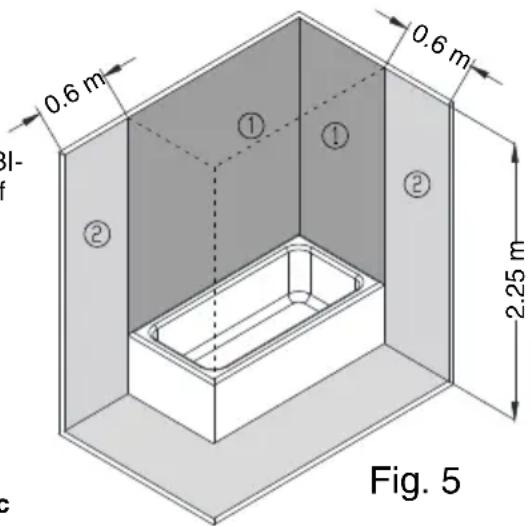
For installations in bathrooms and toilets Regulation IEC 60364-7-701 shall be adhered to.
VOLUME OF PROHIBITION: Zone 1 defined in figure 5.
No switches, sockets or lighting fixtures will be installed.
VOLUME OF PROTECTION: Zone 2 defined in figure 5.
No switches will be installed, however safety sockets or sockets protected by a 30 mA circuit breaker may be installed.
The boiler should be installed outside the VOLUME OF PROHIBITION, in order to prevent water reaching the inside of the appliance. If the boiler has no plug, electrical power should be supplied through a bipolar switch with contact openings of at least 3 mm. The installation should be protected with fuses of a calibre corresponding to the absorbed current. An earth connection should be included in every electrical installation. To make this connection, the boiler plug is provided with the appropriate contact, therefore it is enough for the base of the plug to correspond to that supplied with the appliance. If there is no regulatory “EARTH”, we recommend the installation of a ≤30 mA differential switch.
This appliance complies with the regulation on Radio-electric Disruption and interferences.
WARNING: always service the appliance with official aftersales, included the plug.
USE
START UP
Filling up. Open the shutoff cock as soon as the heater has been installed. Open the hot water taps. Water appears as soon as the unit fills up completely. Close the taps and check the system for leaks.
Don't connect the heater to the power mains if uncertain as to whether it is full or not.
Electric Connection Plug into the mains and press the main power input switch. A light flashes on when the heating element is activated. The thermostat re-connects the heating element after a certain amount of water has been used.
Adjusting water temperature. Allows the user to adjust the temperature of hot water between about 30 ^ (minimum position) and 70 ^ (maximum position).
Position E. (Energy saving). The water reaches a temperature of about 55^ C. In this position the heat losses are minimal and the formation of limescale is virtually eliminated.
It is advisable to have the heater plugged into the mains permanently as the thermostat will only activate the unit whenever it becomes necessary to maintain the selected temperature setting. The expanded polyurethane foaming will neutralize any potential heat loss.
How to empty the unit. The heater should be fully drained if left unused for extended periods or if subject to freezing hazards where
installed. This can be done by means of the safety valve.
Always remember to:
– Cut-off the power supply.
- Shut-off the input cock.
- Open the hot water tap.
MAINTENANCE
The water heater does not need any specific maintenance. Before cleaning the device, disconnect it. Scrubbing it with a smooth cloth or moist sponge is enough. Do not use abrasive materials or detergents.
Any overheating caused by thermostat failures is offset by the safety limiting device cutting both stages off and leaving the heater without power input.
Should any problem arise, the customer is advised to contact the After Sales Services.
THE MANUFACTURER reserves the right to modify the characteristics and specifications of all products without prion notice.
HYDRAULICKÁ INSTALACE
ELEKTRICKÁ INSTALACE
HYDRAULICKÁ INŠTALÁCIA
5 alشكل
natural_image
Simple line drawing of a wall-mounted device with a cylindrical container and cable, no text or symbols present.DETALLE ENCLAVAMIENTO
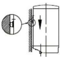
- Safety valve.
- Easing lever (for draining).
- Discharge pipe of the pressure relief device.
- Shut off valve.
- Pressure reducer: it's necessary installed after the "meter" when the pressure is more then 5 kg/cm².
- Earthed plastic sleeves (supplied with the heater).
FR
natural_image
Technical line drawings of mechanical components (no text or symbols)Fig. 3 Fig. 4
VACIADO EN HORIZONTAL Y VERTICAL TOMAS INFERIORES
VACIADO EN VERTICAL
TUBOS TOMAS SUPERIORES
ES
1- Heating element
2- Heating pilot
3- Work. thermostat
4- Safety thermostat
5- Thermostat
FR
1.- Brand name
2.- Models
3.- Emission of nitrogen oxides
4.- Sound power level
5.- Hot water generation: Specified load profile
6.- Hot water generation: Energy-efficiency class
7.- Hot water generation: Energy-efficiency
8.- Annual fuel consumption
9.- Daily fuel consumption
10.- Annual electricity consumption
11.- Daily electricity consumption
12.- Temperature setting for the temperature controller
13.- "Smart" value "1": The information on the hot water generation energy efficiency and on the manual power or fuel consumption applies only whe the intelligent control system is switched on.
14.- Weekly fue consumption with smart control
15.- Weekly fue consumption without smart control
16.- Weekly electricity consumption with smart control
17.- Weekly electricity consumption without smart control
18.- Option to only operate during low-demand periods.
19.- Capacity
20.- Mixed water at 40°C.
FR


- SAFETY AND GENERAL WARNINGS
- ENVIRONMENT
- INFORMATION FOR THE CORRECT MANAGEMENT OF RESIDUES FROM ELECTRIC AND ELECTRONIC DEVICES
- MALFUNCTIONS OR BREAKDOWN
- INSTALLATION
- ACCESORIES
- WALL MOUNTING PROCEDURE
- LOCATION
- HYDRAULIC INSTALATION
- ELECTRIC INSTALLATION
- USE
- START UP
- MAINTENANCE
- HYDRAULICKÁ INSTALACE
- ELEKTRICKÁ INSTALACE
- HYDRAULICKÁ INŠTALÁCIA
- FR
- ES
Brand : FAGOR
Model : MS80 ECO
Category : Boiler