RAID 6805E - Controller ADAPTEC - Free user manual and instructions
Find the device manual for free RAID 6805E ADAPTEC in PDF.
Frequently Asked Questions - RAID 6805E ADAPTEC
User questions about RAID 6805E ADAPTEC
0 question about this device. Answer the ones you know or ask your own.
Ask a new question about this device
Download the instructions for your Controller in PDF format for free! Find your manual RAID 6805E - ADAPTEC and take your electronic device back in hand. On this page are published all the documents necessary for the use of your device. RAID 6805E by ADAPTEC.
USER MANUAL RAID 6805E ADAPTEC
SAS RAID Controllers
Quick Start Guide
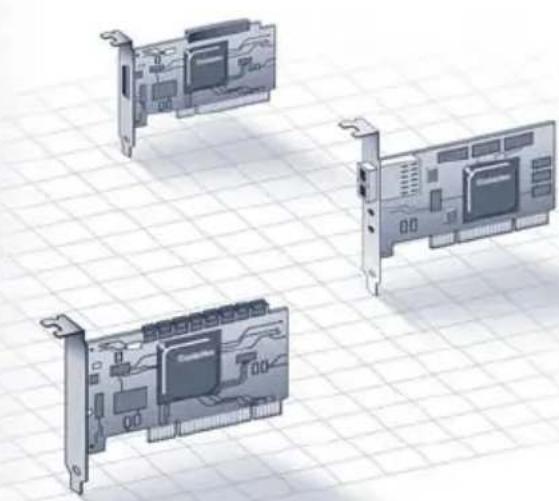
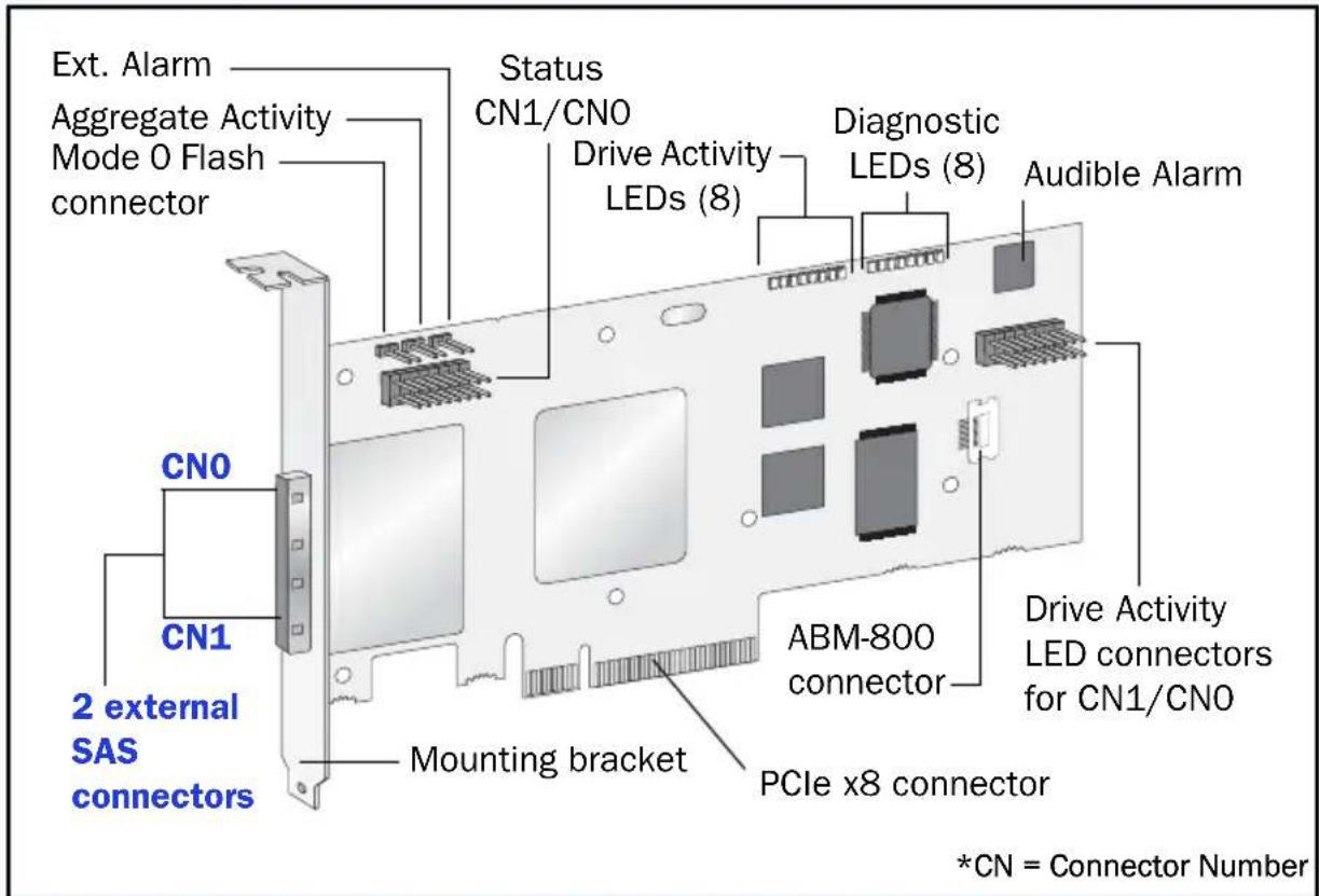
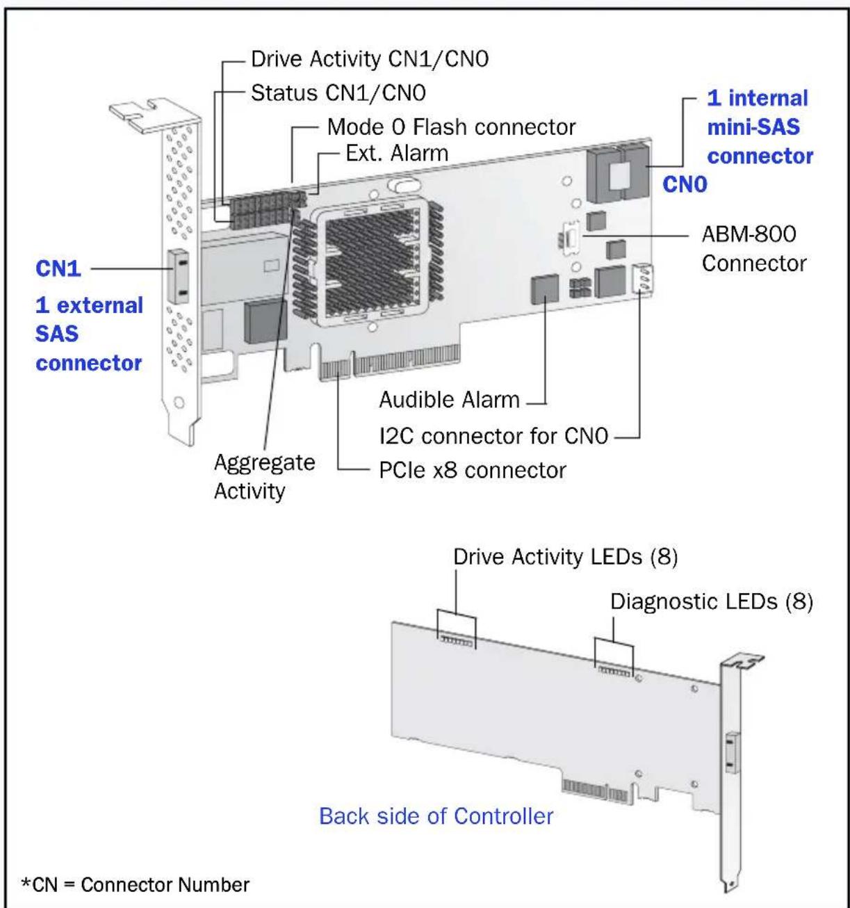
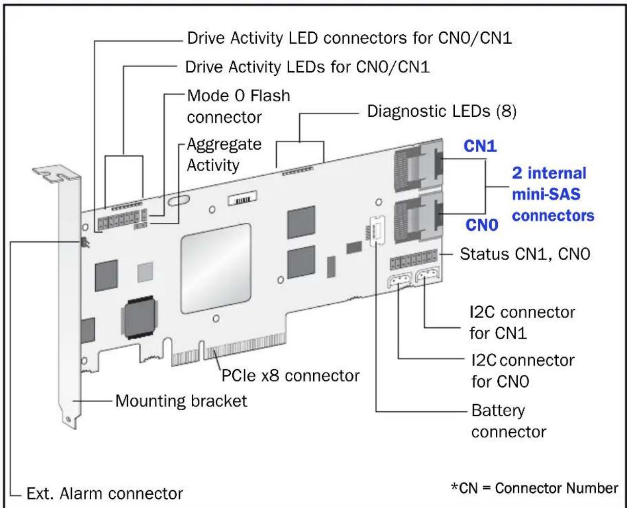
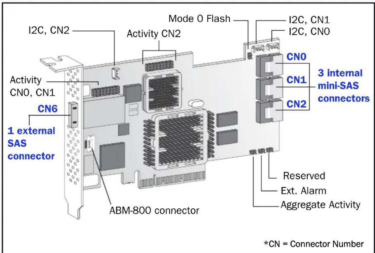
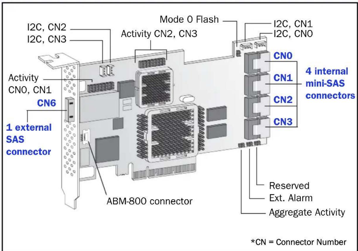
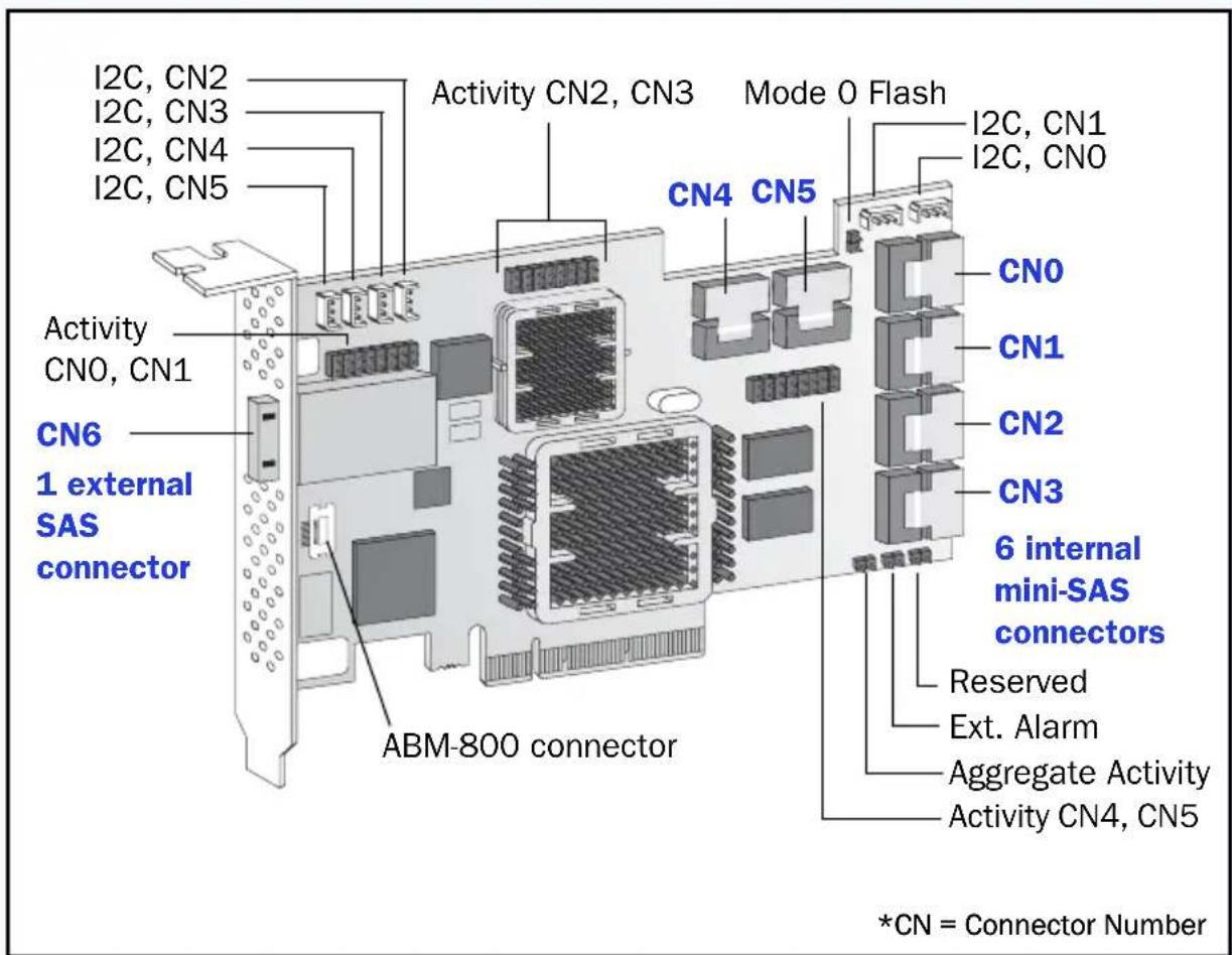
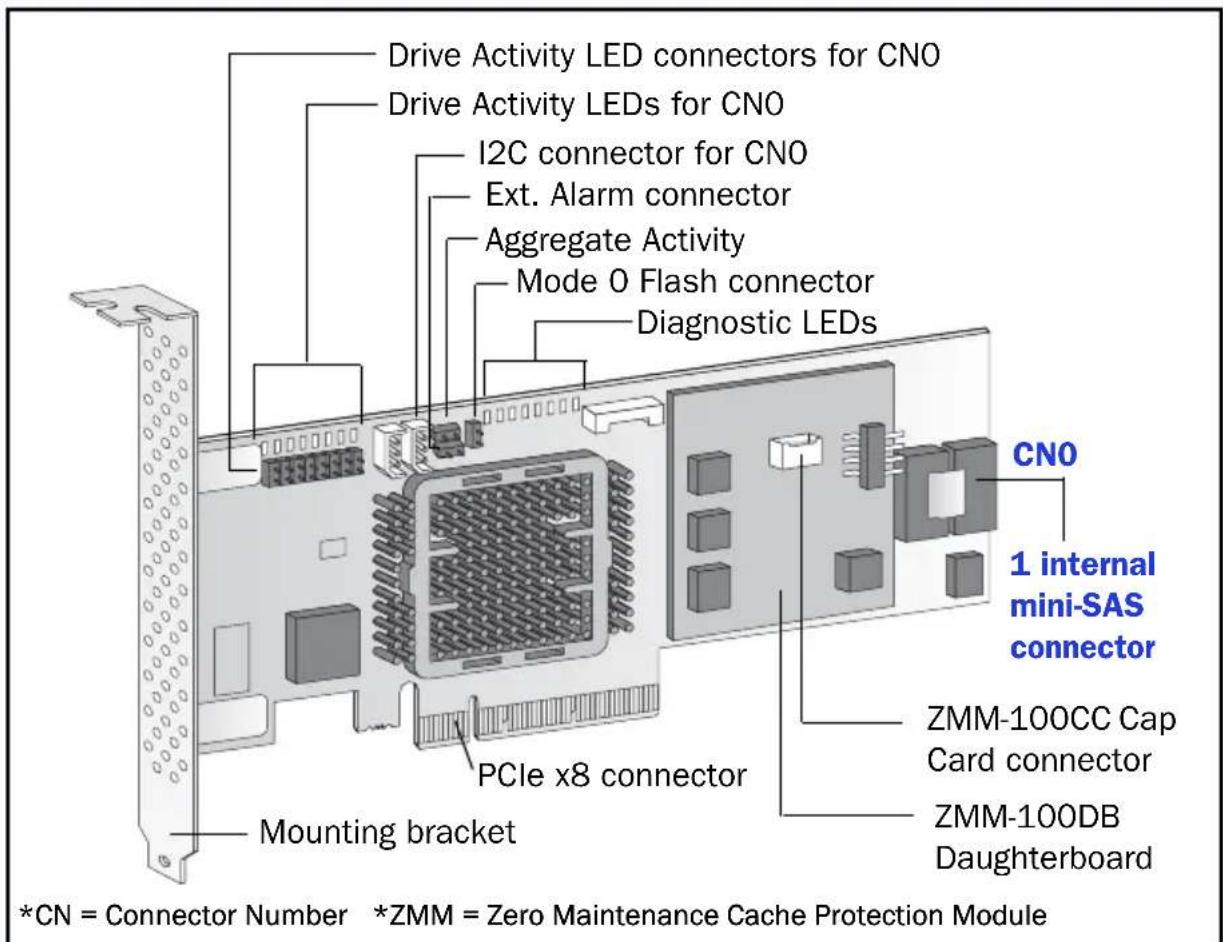
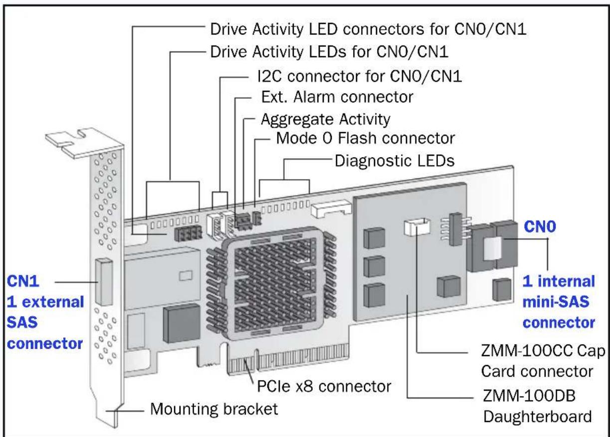
Controller Illustrations
Introduction
This Quick Start Guide describes how to install your Adaptec® by PMC RAID controller, create a bootable RAID 1 or RAID 5 array, and then install your Microsoft® Windows® 2008, Microsoft Windows 7, or Red Hat® Enterprise Linux 5 operating system and controller driver on that array. For other installation options, refer to the Adaptec RAID Controllers Installation and User's Guide included on the Adaptec Installation DVD. For controller illustrations, refer to the last section of this document.
Note: For the latest information about the products described in this guide, supported OSs, and to download drivers, visit www.adaptec.com. For a list of compatible Solid State Drives for Adaptec MaxIQ caching applications, visit www.adaptec.com/compatibility.
Kit Contents
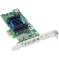
Adaptec RAID controller
Embedded in the controller's BIOS are these utilities:
- Array Configuration Utility (ACU): Used to create, configure and manage arrays
- SerialSelect: Used to modify your controller and disk drive settings
- Disk Utilities: Used to format and verify disk drives
Adaptec Installation DVD
-Drivers and firmware for the Adaptec RAID controller
Adaptec MaxIQ SSD (Solid State Drive) Caching software
-Adaptec Storage Manager: User-friendly application that you can use to create and manage arrays
Adaptec RAID Controller Configuration Utility (ARCCONF): Used to perform basic array and configuration management tasks
- Product documentation for the Adaptec RAID controller, BIOS Utilities, Adaptec Storage Manager, and ARCCONF Utility
Cables (type and quantity vary, depending on controller; cables are included only with Adaptec Kit product, not Adaptec Single product)
Low-profile bracket (depending on controller)
Quick Start Guide (this document)
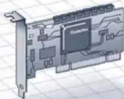
Step 1 Install the Controller

Caution: Electrostatic discharge (ESD) can damage your controller. Follow standard anti-ESD precautions to avoid exposing the controller to static charge.
a If you have a LP controller and a LP computer cabinet, replace the original full-height bracket on the controller card with the LP bracket supplied in the controller kit.
b Turn off the computer and disconnect the power cord.
c Open the cabinet. Refer to the manufacturer's instructions as needed.
d Insert the controller into an available PCIe slot that's compatible with your controller and secure the controller bracket to the chassis.
e Optional—Connect your computer's disk activity LED cable to the LED connector on your controller (not available on some models). Attach the positive lead to pin 1.
f Optional—Connect the controller's I2C connector (not available on some models) to an I2C connector on an internal SAS backplane or enclosure. Use an I2C cable (typically included with the backplane).
g Install and connect any internal hard disk drives (HDDs) or Solid State Drives (SSD) using the appropriate cable(s), then close the computer cabinet.
Note: To build a RAID 1, you must install two HDDs. To build a RAID 5, you must install at least three HDDs.
h Connect any external cables and HDDs or SSDs to the controller.
- Do not attach a cable to the controller unless the other end of the cable is attached to at least one drive. Doing so can cause unstable operation.
- Use high-quality cables—poor quality cables degrade reliability.
Step 2 Create a RAID Array
RAID 1 and RAID 5 arrays are used here as an example. Create a RAID 1 if your controller does not support RAID 5. You can create a different level array in a similar manner.
a Turn on the computer, then when prompted press Ctrl+A to enter the BIOS-based configuration utility. The Menu Options screen displays.
Note: If you have more than one of the same type of controller installed, select your controller, then press Enter.
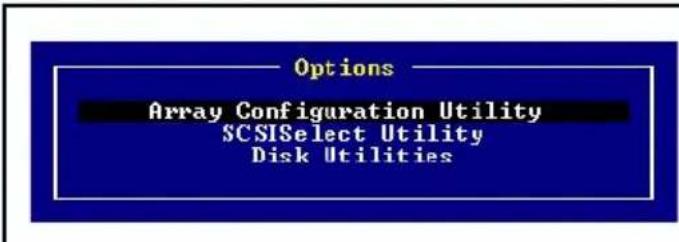
b Select Array Configuration Utility, then press Enter. The ACU Menu displays.
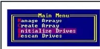
c Select Initialize Drives, then press Enter.
d Select at least three HDDs for a RAID 5 array or two disks for a RAID 1. Press Insert for each selected HDD, then press Enter.
e Press Y, then press Enter. The selected drives are initialized, then the ACU Menu displays.
Warning: Initializing HDDs deletes all data stored on these drives. Back up any data you want to keep before initializing the HDDs.
f Select Create Array, then press Enter.
g Select the HDDs you just initialized, press Insert for each selected HDD, then press Enter.
h On the Array Properties screen, respond as follows:
Array Type
Select RAID 5 or RAID 1, then press Enter.
Array Label Type a name, then press Enter.
Array Size
Press Enter, then press Enter again to use the default granularity of GB.
Stripe Size Press Enter to use the default (256KB).
Read Caching Press Enter to use the default (Yes).
Write Caching
Press Enter to use the default (Enable always).
Create RAID via
Press Enter to use the default (Build/Verify).
[Done] Press Enter.
i When a cache warning message is displayed, type Y.
j Once the array is created, a message tells you that the array can now be used. Press any key to return to the ACU Menu.
Note: Although you can start using the array now, performance is reduced until the build process is complete.
Press Esc until the Exit Utility window appears.
Select Yes, then press Enter. The computer restarts.
Step 3 Set up the Boot Sequence
The process you use to access your computer's BIOS Setup program and set the boot sequence varies by computer manufacturer. Refer to the instructions provided with your specific computer. Steps may be similar to:
a During startup, press the key combination (for example, <F2> , <F1> , <DEL> ) that starts the BIOS Setup program.
b Go to the menu used to specify the boot sequence. Put the DVD drive first—this allows you to perform Step 4 on page 4.
c Go to the menu used to specify the boot priority for HDDs. Put the Adaptec RAID controller first in this sequence.
d Save your changes, exit Setup, and restart the computer.
Step 4 Create the Driver Disk—Linux Only
a Insert the Adaptec Installation DVD and turn on the computer to boot from the DVD.
b Click Create Driver Disk, then select your Red Hat Linux OS version.
c Select your floppy disk drive letter, then select the format you want. You need a full format only if your floppy disk is unformatted.
d Insert the floppy disk, then click OK. The computer creates the driver disk.
e Remove and label the driver disk.
f Continue with the installation of the OS and controller driver, as described in Step 5 below. If your OS is not listed in Step 5, refer to the Adaptec RAID Controllers Installation and User's Guide on the Adaptec Installation DVD.
Step 5 Install the Controller Driver with the OS
Windows 2008, Windows 7
For Windows 2003 or Windows Vista, refer to the Adaptec RAID Controllers Installation and User's Guide on the Adaptec Installation DVD.
a Insert your Windows CD, then restart the computer.
b Follow the on-screen instructions to begin the Windows installation.
c When prompted to specify a location for Windows, select Load Driver.
d Insert the Adaptec Installation DVD, browse to the driver location, then click OK.
e When the driver is found, press Next.
Note: With Adaptec Series 6 controllers, you may see the message 'No drives were found'. Repeat Step c, Step d (without reinserting the DVD), and Step e. On the second attempt, the driver will load successfully.
f Click Next again to accept the default partition configuration, or refer to your Windows documentation to configure partitions manually.
g Follow the on-screen instructions to complete the installation.
Red Hat Enterprise Linux 5
For Red Hat 6 or other Linux versions, refer to the Adaptec RAID Controllers Installation and User's Guide on the Adaptec Installation DVD.
a Insert the first Red Hat installation CD.
b Restart the computer.
c When the Red Hat Welcome screen appears, type linux dd at the Boot: prompt.
d When prompted, insert the driver disk, then select OK.
e Follow the prompts to set up the environment you want.
f If you are installing other third-party devices, install them now. Otherwise, select Done.
g Continue with the Linux installation, according to the Red Hat instructions.
Step 6 Install Adaptec Storage Manager
Before installing Adaptec Storage Manager, ensure that you are logged in with administrator or root privileges. Any customization files you created using the previous version are saved and used in the upgrade.
Windows Installation
a Insert the Adaptec Installation DV D. Select Install Adaptec Storage Manager from the DVD menu. The Installation wizard starts. (If it doesn't start, select Browse the CD/DVD, then click Autorun.)
b Follow the on-screen instructions to complete the installation. When prompted to install SNMP (Simple Network Management Protocol), do not install unless you have a specific requirement for Adaptec Storage Manager to work with SNMP gets and traps.
Linux Installation
On Linux, Adaptec Storage Manager includes the Java Runtime Environment (JRE).
a Insert the Adaptec Installation DVD.
b Mount the Adaptec Installation DVD: mount /dev/cdrom /mnt/cdrom
c Change to the manager directory: cd /mnt/cdrom/ASMCD/linux/manager
d Extract the RPM package and install it: rpm --install./StorMan*.rpm
e Unmount the Adaptec Installation DVD: umount /mnt/cdrom
More Information
For more information about Adaptec RAID controllers, specifications, and updates, visit www.adaptec.com.
To find detailed information about the controllers described in this Quick Start Guide, refer to these documents:
- Readme—Text files located on the Adaptec Installation DVD. These files provide late-breaking technical information.
- Adaptec RAID Controllers Installation and User's Guide—PDF file located on the Adaptec Installation DVD. It provides complete information on how to install and configure your controller and attach devices.
- Adaptec Storage Manager User's Guide—PDF file located on the Adaptec Installation DVD. It provides complete information on how to install and use Adaptec Storage Manager.
- Command Line Utility User's Guide—PDF file located on the Adaptec Installation DVD. It provides complete information on how to use ARCCONF.
- Adaptec Storage Manager Online Help—Adaptec Storage Manager includes embedded online Help that describes how to use Adaptec Storage Manager to create and manage arrays.
Einführung
(Caching in lettuce)
In Linux, Adaptec Storage Manager include l'ambiente JRE (Java Runtime Environment).
cd /mnt/cdrom/ASMCD/linux/manager
Serial Attached SCSI RAID Controllers
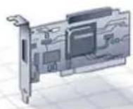
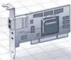
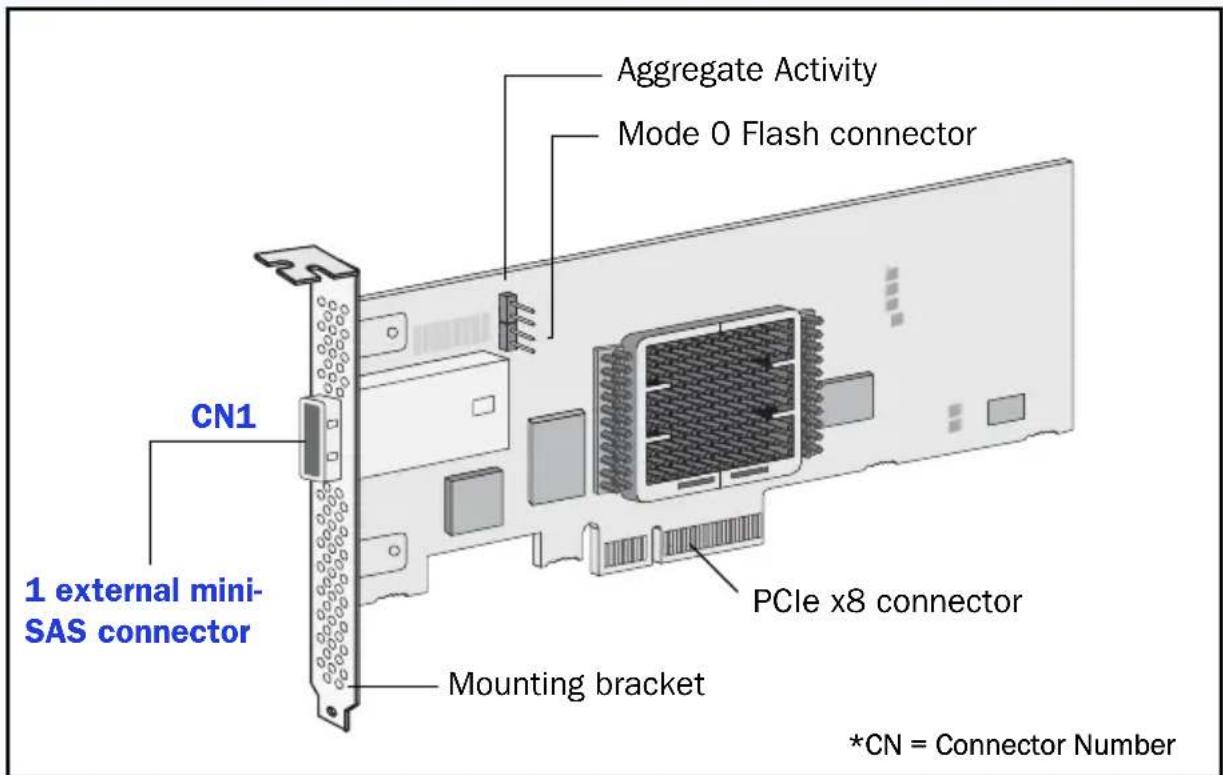
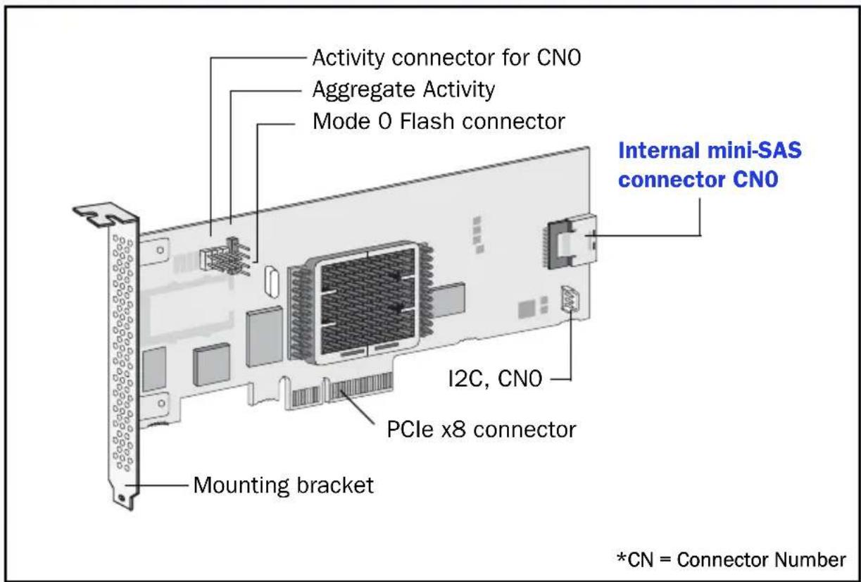
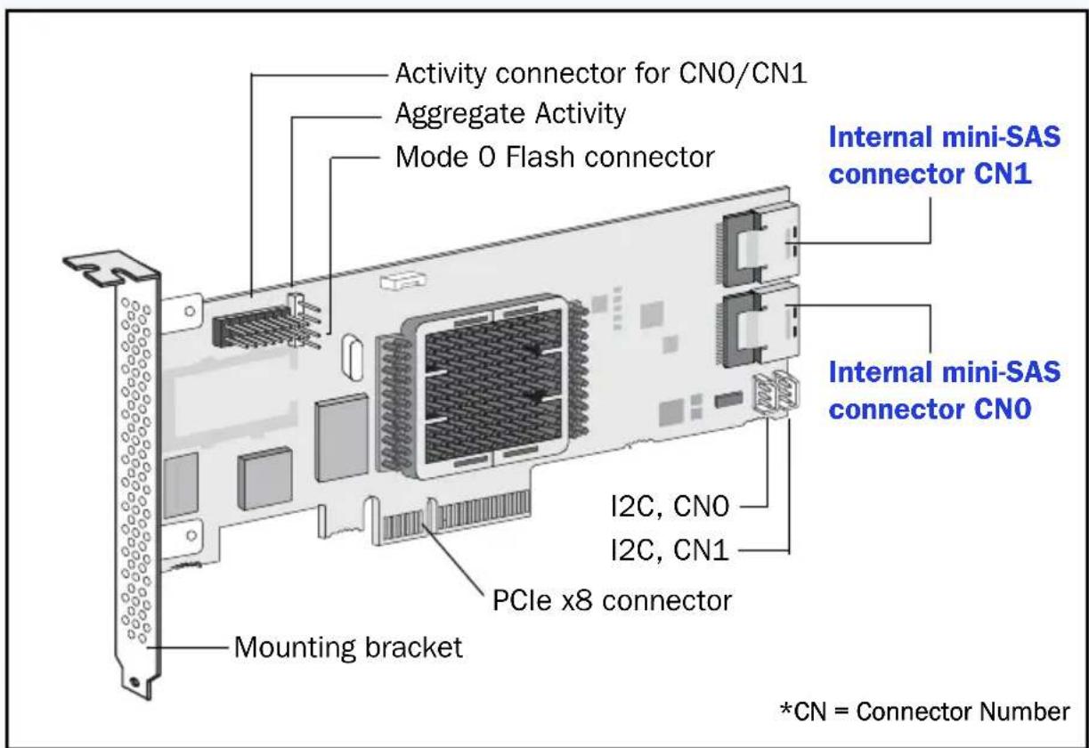
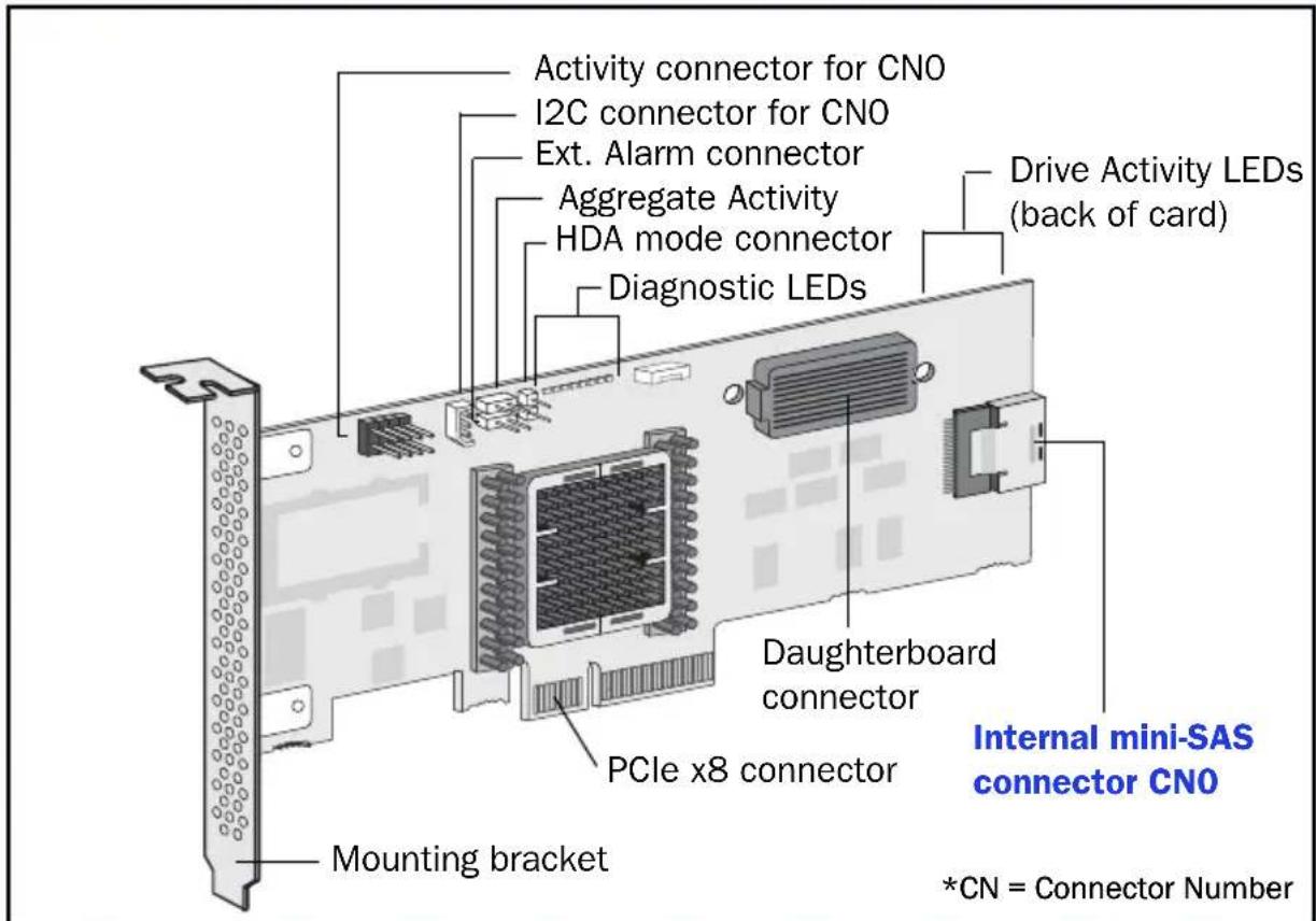
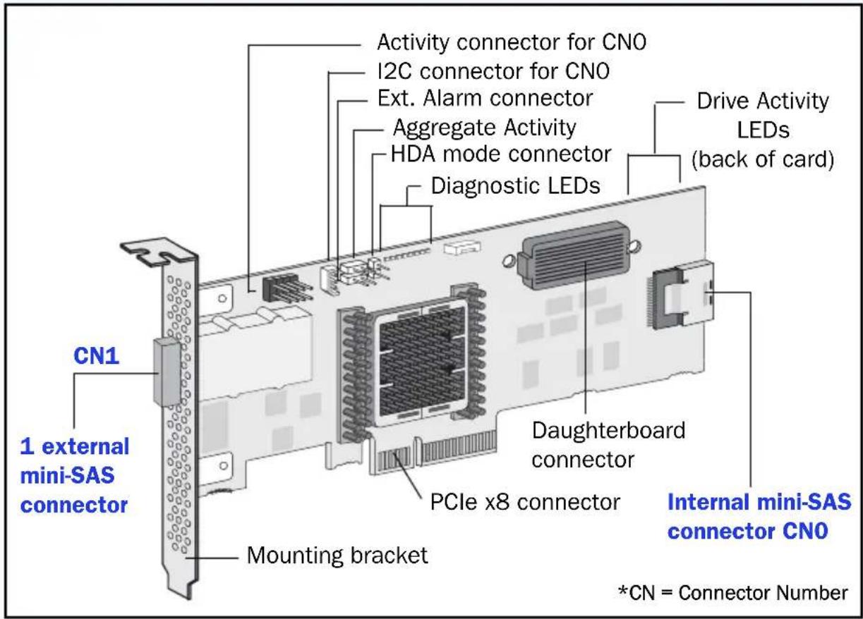
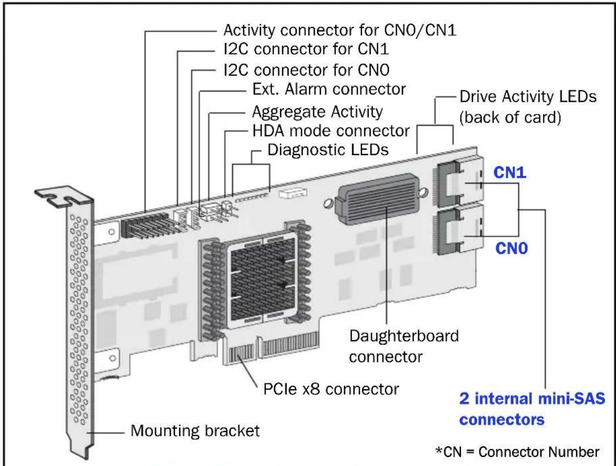
Controller Illustrations
Adaptec 5085
Adaptec 5405

Adaptec 5445
Adaptec 5805/5805Q
Adaptec 51245
Adaptec 51645
Adaptec 52445
Adaptec 5405Z
Adaptec 5445Z
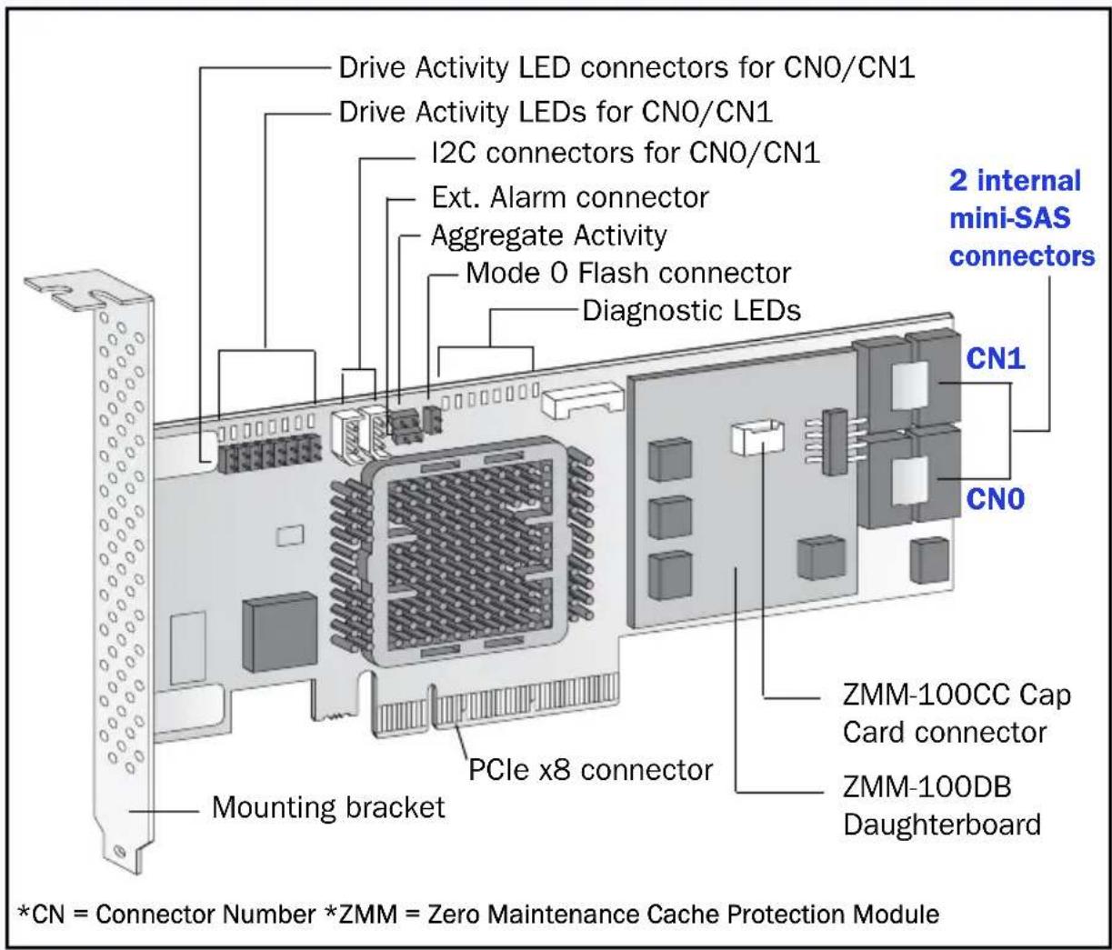
Adaptec 5805Z/5805ZQ
Adaptec 2045
Adaptec 2405/2405Q
Adaptec 2805
Adaptec 6405
Adaptec 6445
Adaptec 6805
Adaptec 6405E
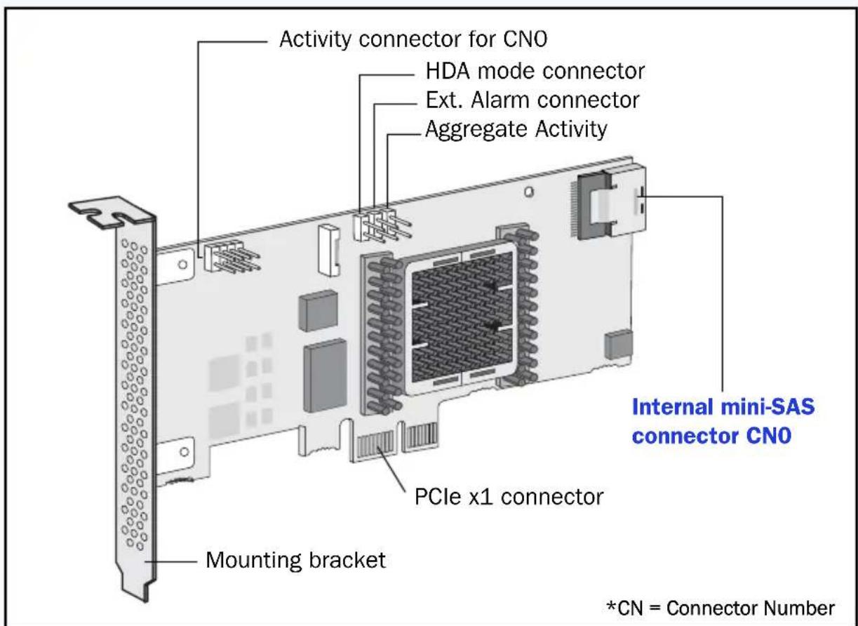
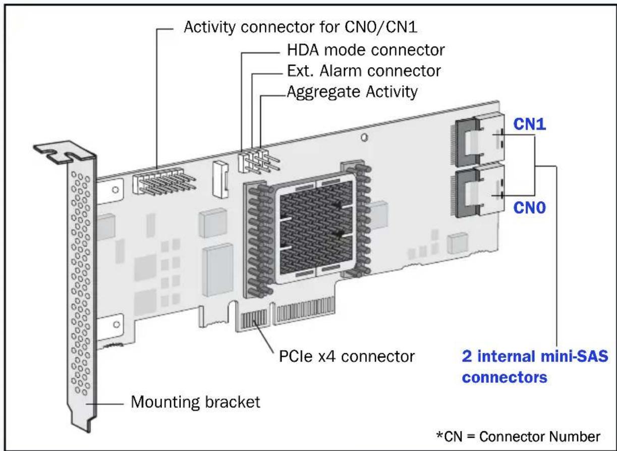
Adaptec 6805E
adaptec
by PMC
PMC-Sierra, Inc.
1380 Bordeaux Drive
Sunnyvale, CA 94089 USA
PMC-Sierra, Inc. 2011
All rights reserved. Adaptec and the Adaptec by PMC
logo are trademarks of PMC-Sierra, Inc.
Part Number: CDP-00261-02UN-A Rev. A