
DDLE Basis 27 - Boiler AEG - Free user manual and instructions
Find the device manual for free DDLE Basis 27 AEG in PDF.
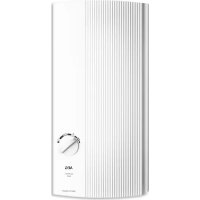



| Product type | Instantaneous water heater with electronic regulation |
| Brand | AEG |
| Model | DDLE Basis 27 |
| Dimensions (H x W x D) | 485 x 226 x 93 mm |
| Weight | 3.6 kg |
| Connected power | 27 kW |
| Rated voltage | 400 V three-phase (3/PE) |
| Temperature range | 30 °C to 60 °C |
| Minimum flow rate for activation | > 3 l/min |
| Maximum permissible pressure | 1 MPa (10 bar) |
| Protection rating | IP25 (recessed) / IP24 (surface-mounted) |
| Nominal capacity | 0.4 L |
| Heating system | Bare wire, scale-resistant |
| Regulation | Electronic with air detector |
| Safety | Safety limiter, pressure switch, frost protection |
| Cleaning | Damp cloth, descaling of fittings |
| Maintenance | Regular cleaning of the filter |
| Spare parts | Available (see manual) |
| Warranty | According to country conditions |
Frequently Asked Questions - DDLE Basis 27 AEG
User questions about DDLE Basis 27 AEG
0 question about this device. Answer the ones you know or ask your own.
Ask a new question about this device
Download the instructions for your Boiler in PDF format for free! Find your manual DDLE Basis 27 - AEG and take your electronic device back in hand. On this page are published all the documents necessary for the use of your device. DDLE Basis 27 by AEG.
USER MANUAL DDLE Basis 27 AEG
Electronically controlled instantaneous water heater
Operation and installation 17
- General information 18
- Safety 18
- Appliance description 19
- Settings 19
- Cleaning, care and maintenance 19
- Troubleshooting 19
INSTALLATION
- Safety 20
- Appliance description 20 9. Preparations 20
- Installation 21
- Commissioning 25
- Shutdown 26
- Troubleshooting 26
- Maintenance 27
- Specification 27
GUARANTEE
ENVIRONMENT AND RECYCLING
SPECIAL INFORMATION
The appliance may be used by children aged 8 and up and persons with reduced physical, sensory or mental capabilities or a lack of experience and know-how, provided that they are supervised or they have been instructed on how to use the appliance safely and have understood the resulting risks. Children must never play with the appliance. Children must never clean the appliance or perform user maintenance unless they are supervised. - Risk of scalding: The tap can reach temperatures in excess of 60°C. Ensure the appliance can be separated from the power supply by an isolator that disconnects all poles with at least 3mm contact separation. - Secure the appliance as described in chapter "Installation / Installation". Observe the maximum permissible pressure (see chapter Installation / Specification / Data table). Drain the appliance as described in chapter "Installation / Maintenance / Draining the appliance".
OPERATION
1. General information
The chapters "Special Information" and "Operation" are intended for both the user and qualified contractors.
The chapter "Installation" is intended for qualified contractors.

Note
Read these instructions carefully before using the appliance and retain them for future reference.
Pass on the instructions to a new user if required.
1.1 Safety instructions
1.1.1 Structure of safety instructions

KEYWORD Type of risk
Here, possible consequences are listed that may result from failure to observe the safety instructions.
» Steps to prevent the risk are listed.
1.1.2 Symbols, type of risk
| Symbol Type of risk | |
| ! | Injury |
| Electrocution | |
| Burns (burns, scalding) | |
1.1.3 Keywords
| KEYWORD Meaning | |
| DANGER | Failure to observe this information will result in seri-ous injury or death. |
| WARNING | Failure to observe this information may result in seri-ous injury or death. |
| CAUTION | Failure to observe this information may result in non-serious or minor injury. |
1.2 Other symbols in this documentation

Note
General information is identified by the adjacent symbol.
» Read these texts carefully.
| Symbol Meaning | |
| ! | Material losses (appliance damage, consequential losses and environmental pollution) |
| Appliance disposal | |
» This symbol indicates that you have to do something. The action you need to take is described step by step.
1.3 Units of measurement

Note
All measurements are given in mm unless stated otherwise.
2. Safety
2.1 Intended use
This appliance is intended for domestic use. It can be used safely by untrained persons. The appliance can also be used in a non-domestic environment, e.g. in a small business, as long as it is used in the same way.
This pressurised appliance is suitable for heating domestic hot water or for reheating preheated water. The appliance can supply one or more draw-off points.
Any other use beyond that described shall be deemed inappropriate. Observation of these instructions and of instructions for any accessories used is also part of the correct use of this appliance.
2.2 General safety instructions

CAUTION Burns
During operation, the tap can reach temperatures in excess of 60°C.
There is a risk of scalding at outlet temperatures in excess of 43°C.

CAUTION Burns
If operating with preheated water, e.g. from a solar thermal system, the DHW temperature may vary from the selected set temperature.

WARNING Injury
The appliance may be used by children aged 8 and up and persons with reduced physical, sensory or mental capabilities or a lack of experience and know-how, provided that they are supervised or they have been instructed on how to use the appliance safely and have understood the resulting risks. Children must never play with the appliance. Children must never clean the appliance or perform user maintenance unless they are supervised.
Where children or persons with limited physical, sensory or mental abilities are allowed to use this appliance, we recommend a permanent temperature limit. A qualified contractor can set the limit for you.

Material losses
The user should protect the appliance and its tap against frost.
2.3 CE designation
The CE designation shows that the appliance meets all essential requirements according to the:
Low Voltage Directive, Electromagnetic Compatibility Directive. The maximum permissible mains impedance is indicated in chapter "Installation / Specification / Data table".
2.4 Test symbols
See type plate on the appliance.
Country-specific approvals and certifications: Germany
A general test certificate as verification of suitability regarding noise emissions has been issued for this appliance, based on the State Building Regulations [Germany].
3. Appliance description
The electronically controlled instantaneous water heater with automatic output matching keeps the outlet temperature constant up to the output limit. The temperature is then selected via the draw-off tap.
Heating system
The bare wire heating system has a pressure-tested plastic casing. The heating system is suitable for hard and soft water areas. This heating system has a low susceptibility to scale build-up. This system ensures rapid and efficient DHW availability.

Note
The appliance is equipped with an air detector that largely prevents damage to the heating system. If, during operation, air is drawn into the appliance, the appliance shuts down for one minute, thereby protecting the heating system.
4. Settings
The DHW outlet temperature can be variably adjusted.
| Hand wash basin (approx. 35 °C) |
| Shower (approx. 40 °C) |
| Bath (approx. 45 °C) |
| Kitchen sink (approx. 55 °C) |
Turn the temperature selector to the required temperature.
Temperature limit
Your qualified contractor can set a temperature limit of up to 43°C inside the appliance. With the temperature limit enabled, you can turn the temperature selector across its full range. You can now set the outlet temperature only between 30°C and 43°C.

Note
Should the outlet temperature fail to reach the required level with the draw-off valve fully open and the temperature selector set to maximum, then more water is flowing through the appliance than can be heated by the heating system. The appliance is at its output limit.
» Reduce the water volume at the draw-off valve.
Recommended setting for operation with a thermostatic valve
Set the temperature at the appliance to the maximum temperature.
Following an interruption of the water supply

Material losses
In order to prevent the destruction of the bare wire heating system, return the appliance into use following an interruption of the water supply as follows:
» Disconnect the appliance from the power supply by removing the fuses/tripping the MCBs.
Open the tap for one minute until the appliance and its upstream cold water inlet line are free of air. Switch the mains power back ON again.
5. Cleaning, care and maintenance
Never use abrasive or corrosive cleaning agents. A damp cloth is sufficient for cleaning the appliance. Check the taps regularly. Limescale deposits at the tap outlets can be removed using commercially available descaling agents.
6. Troubleshooting
| Problem Cause Remedy | ||
| The appliance will not start despite the DHW valve being fully open. | There is no voltage at the appliance. | Check the fuses/ MCBs in your fuse box/distribution panel. |
| The flow rate is too low. The aerator in the tap or the shower head is scaled up or contaminated. | Clean and/or descale the aerator or shower head. | |
| Required temperature > 45 °C is not achieved. | The water supply has been interrupted. | Vent the appliance and the cold water inlet line (see chapter "Operation / Settings"). |
| The cold water inlet temperature is > 45 °C. | Reduce the cold water inlet temperature. | |
If you cannot remedy the fault, notify your qualified contractor. To facilitate and speed up your enquiry, please provide the serial number from the type plate (000000-0000-0000):
D0000041614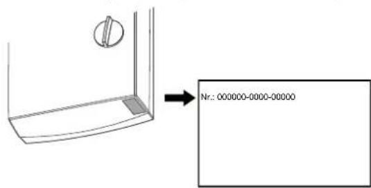
INSTALLATION
7. Safety
Only a qualified contractor should carry out installation, commissioning, maintenance and repair of the appliance.
7.1 General safety instructions
We guarantee trouble-free function and operational reliability only if original accessories and spare parts intended for the appliance are used.

Material losses
Observe the maximum inlet temperature. Higher temperatures may damage the appliance. You can limit the maximum inlet temperature by installing a central thermostatic valve.
72 Instructions, standards and regulations

Note
Observe all applicable national and regional regulations and instructions.
The protection rating IP 25 (hoseproof) can only be ensured with a correctly fitted cable grommet. The specific electrical resistance of the water must not fall below that stated on the type plate. In a linked water network, factor in the lowest electrical resistance of the water (see chapter "Installation / Specification / Data table"). Your water supply utility will advise you of the specific electrical water resistance or conductivity.
8. Appliance description
8.1 Standard delivery
The following are delivered with the appliance:
- Wall mounting bracket
- Threaded studs, screws and rawl plugs for the wall mounting bracket. Installation template. 2 twin connectors (cold water with shut-off valve). Flat gaskets. Cable grommet (power cable from above / below).
- Screws / rawl plugs for fixing the back panel in the case of water connection on finished walls. Additional flow limiter in the cold water pipe (only DDLE Basis 18/21/24).
8.2 Accessories
Tap
ADEo 70 WD Mono lever mixer tap with bath / shower changeover
Stove connection set
Connection set for the power connection of the DDLE Basis 11 and DDLE Basis 13
Installation accessories
Pipe assembly, undersink installation UT 104, connections: Finished walls, G 3/8, top. Water connections with 12 mm compression fitting.
Universal mounting frame
Mounting frame with electrical connections.
Pipe assembly for undersink appliances
You will need the undersink installation set if you use the water connections (G 3/8 A) at the top of the appliance.
Pipe assembly for offset installation
You will need the pipe assembly with bends if you intend to offset the appliance by 90mm downwards from the water connection.
Pipe assembly for replacing a gas water heater
You will need the pipe assembly if you are using the existing gas water heater connections (cold water connection on the left-hand side, DHW connection on the right-hand side).
Load shedding relay (LR 1-A)
The load shedding relay for installation in the distribution board provides priority control for the instantaneous water heater when other appliances, such as electric storage heaters, are being operated simultaneously.
ZTA 3/4 - Central thermostatic valve
The thermostatic valve is for central premixing, for example on an instantaneous water heater with solar thermal system.
9. Preparations
9.1 Installation site

Material losses
Install the appliance in a room free from the risk of frost.
Always install the appliance vertically and near the draw-off point.
The appliance is suitable for undersink and oversink installations.
Undersink installation 26_02_02_1345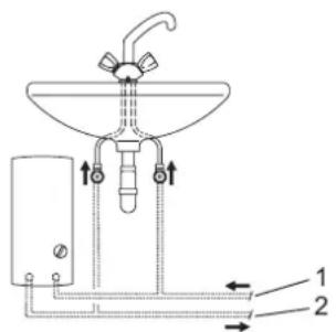
Oversink installation 26_02_02_1344
Mount the appliance on the wall. The wall must have a sufficient load-bearing capacity.
9.2 Water installation
A safety valve is not required.
Flush the water line thoroughly. Ensure that the flow rate for switching on the appliance is achieved (see chapter "Installation / Specification / Data table", On). If the flow rate is not achieved, remove the flow limiter (see chapter "Installation / Installation, Removing the flow limiter"). If the required flow rate is not achieved when the draw-off valve is fully opened, increase the water line pressure.
Taps
Use appropriate pressure taps. Open taps are not permitted.

Note
Never use the shut-off valve in the cold water inlet to reduce the flow rate. The shut-off valve is intended to shut off the appliance.
Permissible water line materials
Cold water inlet line:
Galvanised steel pipe, stainless steel pipe, copper pipe or plastic pipe
DHW outlet line: Stainless steel pipe, copper pipe or plastic pipe

Material losses
If plastic pipework is used, take into account the maximum inlet temperature and the maximum permissible pressure (see chapter "Installation / Specification / Data table").
Flexible water connection lines
If the appliance is installed with flexible water connection lines, ensure that the bayonet fittings of the pipe bends do not become twisted inside the appliance. Secure the back panel at the bottom with two additional screws.
10. Installation
10.1 Standard installation
- Electrical connection from above; installation on unfinished walls. Water connection on unfinished walls.
- DDLE Basis 18/21/24: Connected load 21kW preset. For further installation options, see chapter "Installation / Installation / Installation options": Electrical connection from below on unfinished walls.
- Electrical connection on finished walls.
- Connecting a load shedding relay. Undersink installation, water connections from above. Water installation on finished walls. Operation with preheated water. Temperature limit.
Opening the appliance: Open the appliance by releasing the snap lock.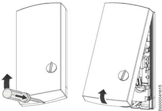
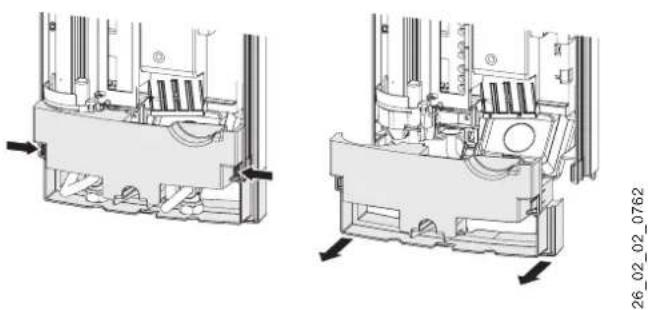
Remove the back panel by pressing the two locking hooks and pulling the lower section of the back panel forwards.
Preparing the power cable.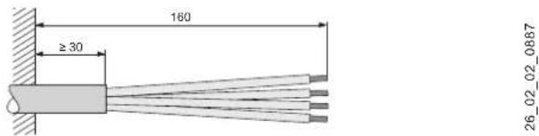
Fitting the wall mounting bracket: Mark out the holes for drilling with the installation template. If the appliance is to be installed with water connections on finished walls, also mark out the fixing holes in the lower part of the template.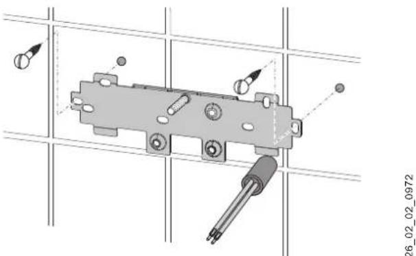
Drill the holes and secure the wall mounting bracket with 2 screws and 2 rawl plugs (screws and rawl plugs are part of the standard delivery). Fit the threaded stud provided. Mount the wall mounting bracket.
Fitting the cable grommet.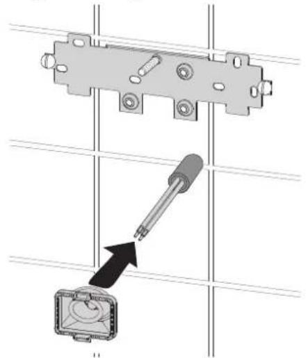
26_02_02_0950
Fit the cable grommet. For connecting cables larger than 6 mm², enlarge the hole in the cable grommet.
Making the water connection

Material losses
Carry out all water connection and installation work in accordance with regulations.
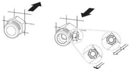
Seal and insert the twin connectors.

Material losses
Never use the shut-off valve in the cold water inlet to reduce the flow rate.
Preparing the back panel

Material losses
If you break out the wrong knock-out by mistake, use a new back panel.
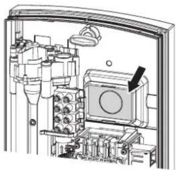
Break out the cable grommet knock-out in the back panel. Deburr the sharp edges with a file if necessary.
Installing the appliance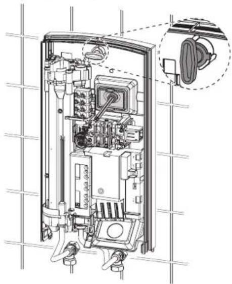
Push the back panel over the threaded stud and the cable grommet. Pull the cable grommet by the locking hooks into the back panel using pliers, until both locking hooks audibly click into place. Remove the transport plugs from the water connections. Push the back panel firmly against the wall. Lock the fixing toggle by turning it 90° clockwise.
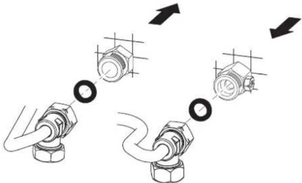
Screw the water connection pipes with flat gaskets onto the twin connectors.

Material losses
The strainer must be fitted for the appliance to function.
When replacing an appliance, check whether the strainer is installed (see chapter "Installation / Maintenance").
Removing / replacing the flow limiter

Note
Never remove the flow limiter if you are using a thermostatic valve.
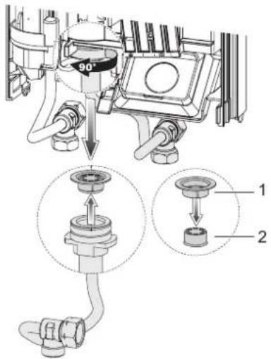
1 Plastic profile washer 2 Flow limiter
Remove the flow limiter. Re-insert the plastic profile washer.
DDLE Basis 18/21/24: Replace the flow limiter
If 24 kW connected load has been selected, replace the fitted flow limiter (white) with the flow limiter supplied (orange, fixed to the cold water pipe).
Making the electrical connection

WARNING: Electrocution
Carry out all electrical connection and installation work in accordance with relevant regulations.

WARNING: Electrocution
The connection to the power supply must be in the form of a permanent connection in conjunction with the removable cable grommet. Ensure the appliance can be separated from the power supply by an isolator that disconnects all poles with at least 3 mm contact separation.

WARNING: Electrocution
Ensure that the appliance is earthed.

Material losses
Observe the type plate. The specified voltage must match the mains voltage.
Connect the power cable to the mains terminal (see chapter "Installation / Specification / Wiring diagram").
DDLE Basis 18/21/24: Re-plugging the coding card
In its delivered condition, the appliance is plugged to 21 kW. When changing to a different connected load, carry out the following steps:
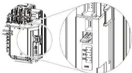
» Re-plug the coding card according to the actual connected load (for connected load options and fuse protection of the appliance, see chapter "Installation / Specification / Data table").
Tick the selected connected load on the type plate. Please use a ballpoint pen to do this.
Fitting the lower section of the back panel
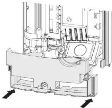
Fit the lower section into the back panel. Click the lower section of the back panel into place. Align the mounted appliance by loosening the fixing toggle, aligning the power supply and back panel, and then re-tightening the fixing toggle. If the appliance back panel does not rest against the wall, you can secure the appliance with two additional screws (see chapter "Installation / Installation options / Water installation on finished walls").
10.2 Installation options
10.2.1 Electrical connection from below on unfinished walls
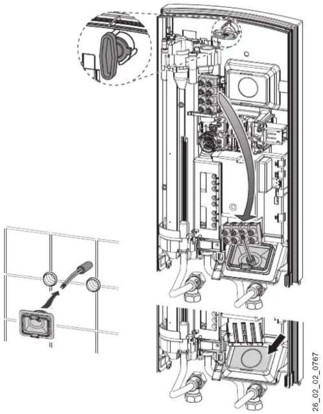
Fit the cable grommet.

Material losses: If you break out the wrong knock-out by mistake, use a new back panel.
Break out the cable grommet knock-out in the back panel. Deburr the sharp edges with a file if necessary. Reposition the mains terminal in the appliance from the top to the bottom. Push the back panel over the threaded stud and the cable grommet. Pull the cable grommet by the locking hooks into the back panel using pliers, until both locking hooks audibly click into place. Push the back panel firmly against the wall. Lock the fixing toggle by turning it 90° clockwise.
10.2.2 Electrical connection on finished walls

Note
This type of connection changes the protection rating of the appliance.
Change the type plate. Cross out "IP 25" and mark the box "IP 24". Please use a ballpoint pen to do this.

Material losses
If you break out the wrong knock-out by mistake, use a new back panel.
Cleanly cut or break out the required opening in the appliance back panel (see chapter "Installation / Specification / Dimensions and connections"). De-burr the sharp edges with a file if necessary.
Route the power cable through the cable grommet and connect it to the mains terminal.
10.2.3 Connecting a load shedding relay
Install a load shedding relay in the distribution board in conjunction with other electric appliances, e.g. electric storage heaters. The relay responds when the instantaneous water heater starts.

Material losses
Connect the phase that switches the load shedding relay to the indicated terminal of the mains terminal in the appliance (see chapter "Installation / Specification / Wiring diagram").
10.2.4 Undersink installation, water connections - from above
An undersink installation with water connections from above can be achieved with an additional pipe assembly for undersink appliances. Cleanly break out the water pipe knock-outs in the back panel and fit the pipe assembly.
10.2.5 Water installation on finished walls

Note
This type of connection changes the protection rating of the appliance.
» Change the type plate. Cross out "IP 25" and mark the box "IP 24". Please use a ballpoint pen to do this.
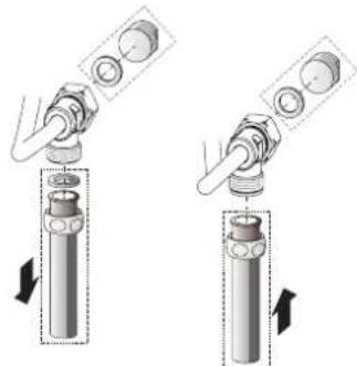
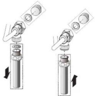
» Fit the water plugs with gaskets in order to seal the connection for unfinished walls. » Fit a suitable pressure tap.
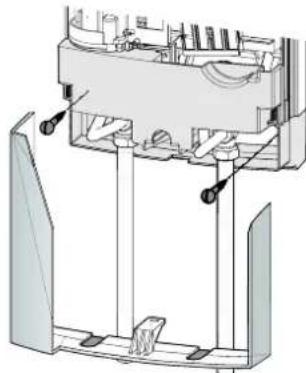
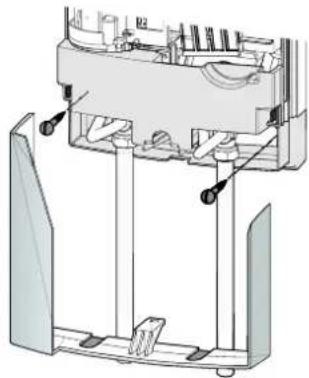
Click the lower section of the back panel into place in the upper section of the back panel. » Secure the connection pipes to the appliance. Secure the back panel at the bottom with two additional screws.

Material losses
If you break out the wrong knock-out by mistake, use a new back panel.
Cleanly break out the knock-outs in the appliance cover. Deburr the sharp edges with a file if necessary.
Slide the lower section of the back panel under the tap connection pipes. Click the lower section of the back panel into place. Secure the connection pipes to the appliance.
10.2.6 Operation with preheated water
You can limit the maximum inlet temperature by installing a central thermostatic valve.
10.2.7 Temperature limit

CAUTION Burns
If operating with preheated water, the set temperature limit and anti-scalding protection may be ineffective.
In this case, limit the temperature with an upstream central thermostatic valve.
You can set the temperature limit inside the appliance cover to 43°C.
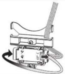
Push the set value transducer cable plug onto the 43°C temperature limiter.
After enabling the temperature limit, you can only select temperatures between 30 and 43°C.
10.3 Completing the installation
Open the shut-off valve in the twin connector or the cold water inlet line.
11. Commissioning

WARNING Electrocution. Commissioning may only be carried out by a qualified contractor in accordance with safety regulations.
11.1 Initial start-up
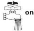
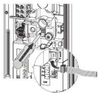
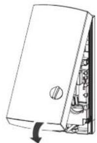
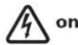
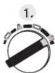
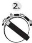
Open and close all connected draw-off valves several times, until all air has been vented from the pipework and the appliance. Carry out a tightness check. Activate the safety pressure limiter by firmly pressing in the reset button (safety pressure limiter disabled in the delivered condition). Plug the temperature selector cable plug into the PCB. Fit the appliance cover. The appliance cover must audibly click into place. Check that the appliance cover is seated correctly. Switch the mains power ON. Calibrate the temperature. Turn the temperature selector fully clockwise then fully anti-clockwise. Check the function of the appliance.
Appliance handover
Explain the functions of the appliance to the user. Show the user how to operate the appliance. Make the user aware of potential dangers, especially the risk of scalding. Hand over these instructions.
11.2 Recommissioning
Vent the appliance and the cold water inlet line (see chapter "Operation / Settings"). See chapter "Installation / Installation / Commissioning / Initial start-up".
12. Shutdown
Isolate all poles of the appliance from the power supply.
Drain the appliance (see chapter "Installation / Maintenance").
13. Troubleshooting

WARNING Electrocution
To test the appliance, it must be supplied with power.
Possible indications of diagnostic traffic light (LED)
| Red Illuminates in the event of a fault |
| Yellow Illuminates during heating mode |
| Green Flashing: Appliance is supplied with mains power |
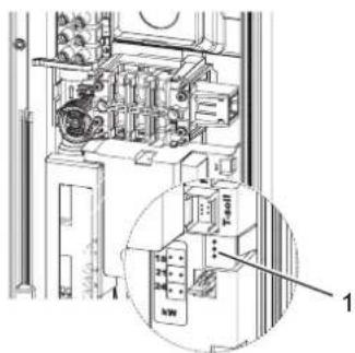
1 Diagnostic traffic light
| Fault / diagnostic traffic light LED display | Cause Remedy | |
| The flow rate is too low. The strainer in the | the appliance is dirty. Clean the strainer. | |
| The set temperature is not achieved. | One phase down. | Check the fuse/MCB in your fuse box/distribution panel. |
| The heating system does not switch on. | The system detects air in the water. Heating output stops temporarily. | The appliance restarts after one minute. |
| No hot water and no traffic light display. | The MCB/fuse has responded/blown. | Check the fuse/MCB in your fuse box/distribution panel. |
| The safety pressure limiter has tripped. | Remove the cause of the fault (e.g. faulty pressure washer). | |
| Protect the heating system against overheating by opening a draw-off valve downstream of the appli- ance for one minute. This depressurises and cools down the heating system. | ||
| Activate the safety pressure limiter at flow pressure by pressing the reset button (see chapter "Installa-tion / Commissioning / Initial start-up"). | ||
| The PCB is faulty. | Check the PCB and replace if required. | |
| Traffic light display: Green flashing or constantly on | The PCB is faulty. | Check the PCB and replace if required. |
| No hot water at a flow rate of >3 l/min. | The flow meter DFE is not plugged in. | Plug the flow meter plug back in. |
| The flow meter plug is faulty. | Check the flow meter and replace if required. | |
| Traffic light display: Yellow constantly on; green flashing | The high limit safety cut-out has responded or its lead is broken. | Check the high limit safety cut-out and replace if required. |
| No hot water at a flow rate of >3 l/min. | ||
| The heating system is faulty. | Check the heating system resistor and replace if required. | |
| The PCB is faulty. | Check the PCB and replace if required. | |
| Traffic light display: Yellow constantly on; green flashing | The outlet sensor has been pulled off. A lead is broken. | Plug in the outlet sensor or replace if required. |
| Traffic light display: Red constantly on; green flashing | The cold water sensor is faulty. | Check the PCB and replace if required. |
| No hot water Required temperature >45 °C is not achieved. | The cold water inlet temperature exceeds 45 °C. | Reduce the cold water inlet temperature to the ap- pliance. |
| Traffic light display: Red constantly on; green flashing | The outlet sensor is faulty (short circuit). | Check the outlet sensor and replace if required. |
14. Maintenance

WARNING Electrocution Before any work on the appliance, disconnect all poles from the power supply.
Draining the appliance
You can drain the appliance for maintenance work or to protect it from frost.

WARNING Burns Hot water may escape when the appliance is being drained.
Close the shut-off valve in the twin connector or the cold water inlet line. Open all draw-off valves. Undo the water connections on the appliance. If dismantled, store the appliance in a room free from the risk of frost, as water residues remaining inside the appliance can freeze and cause damage.
Cleaning the strainer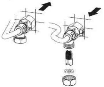
If dirty, clean the strainer in the threaded cold water fitting. Close the shut-off valve in the cold water inlet line before removing, cleaning and refitting the strainer.
15. Specification
15.1 Dimensions and connections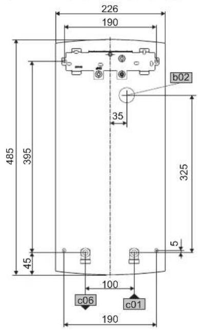
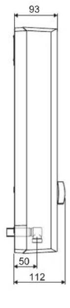
| b02 Entry electrical cables I | ||
| c01 Cold water Inlet Male thread G 1/2 A | ||
| c06 DHW outlet | Male thread | G 1/2 A |
Alternative connection options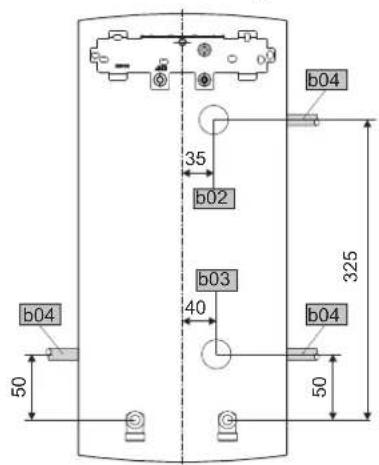
| b02 | Entry electrical cables I |
| b03 | Entry electrical cables II |
| b04 | Entry electrical cables III |
15.2 Wiring diagram
3/PE ~ 380 - 415 V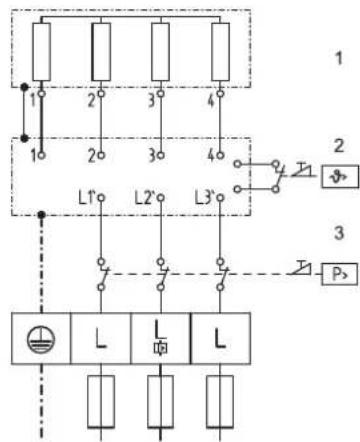
1 Heater 2 High limit safety cut-out 3 Safety pressure limiter
Load shedding relay LR 1-A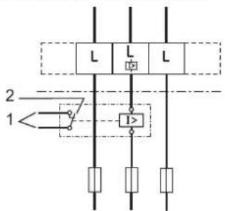
1 Control cable to the contactor of the second appliance (electrical storage heater for example). 2 Control contact opens when switching the instantaneous water heater on.
15.3 DHW output
The DHW output is subject to the mains voltage, the appliance's connected load and the cold water inlet temperature. The rated voltage and rated output can be found on the type plate (see chapter "Operation / Troubleshooting").
Specific electrical resistance and specific electrical conductivity (see chapter "Installation / Specification / Data table").
| Standard specifica-tion at 15 °C | 20 °C | 25 °C | ||||||
| Resist- ance ρ | Conductiv- ity Ω | Resist- ance ρ | Conductiv- ity Ω | Resist- ance ρ | Conductiv- ity Ω | |||
| Ωcm | mS/m | μS/cm | Ωcm | mS/m | μS/cm | Ωcm | mS/m | μS/cm |
| 900 | 111 | 1111 | 800 | 125 | 1250 | 735 | 136 | 1361 |
| 1000 | 100 | 1000 | 890 | 112 | 1124 | 815 | 123 | 1227 |
| 1100 | 91 | 909 | 970 | 103 | 1031 | 895 | 112 | 1117 |
| 1200 | 83 | 833 | 1070 | 93 | 935 | 985 | 102 | 1015 |
| 1300 | 77 | 769 | 1175 | 85 | 851 | 1072 | 93 | 933 |
15.5 Pressure drop
Taps
| Pressure drop at taps at flow rate of 10 l/min | ||
| Mono lever mixer tap, approx. | MPa | 0.04 - 0.08 |
| Thermostatic valve, approx. | MPa | 0.03 - 0.05 |
| Hand shower, approx. | MPa | 0.03 - 0.15 |
Sizing the pipework
When calculating the size of the pipework, a pressure drop for the appliance of 0.1 MPa is recommended.
15.6 Fault conditions
In case of faults, loads up to a maximum of 95°C at a pressure of 1.2 MPa can occur temporarily in the installation.
15.7 Details on energy consumption
Product data complies with EU regulations relating to the Directive on the eco-design of energy related products (ErP).
| DDLE Basis 11 | DDLE Basis 13 | DDLE Basis 18 | DDLE Basis 18/21/24 | DDLE Basis 27 | ||
| 229296 | 229297 | 222388 | 222390 | 222391 | ||
| Manufacturer | AEG Haustechnik | AEG Haustechnik | AEG Haustechnik | AEG Haustechnik | AEG Haustechnik | |
| Load profile | XS | XS | S | S | S | |
| Energy efficiency class | A | A | A | A | A | |
| Annual power consumption | kWh | 473 | 473 | 477 | 477 | 481 |
| Energy conversion efficiency | % | 39 | 39 | 39 | 39 | 39 |
| Default temperature setting | °C | 60 | 60 | 60 | 60 | 60 |
| Sound power level | dB(A) | 15 | 15 | |||
| Special information on measuring efficiency | none | none | none | Data at Pmax. | none |
15.8 Data table
| DDLE Basis | 11 | DDLE Basis 13 | DDLE Basis 18 | DDLE Basis 18/21/24 | DDLE Basis 27 | |||||||||
| 229296 229297 222 | 388 222 | 390 | 222391 | |||||||||||
| Electrical data | ||||||||||||||
| Rated voltage | V | 380 | 400 | 380 | 400 | 415 | 380 | 400 | 415 | 380 | 400 | 415 | 380 | 400 |
| Rated output | kW | 10.1 | 11 | 12.2 | 13.5 | 14.5 | 16.2 | 18 | 19.4 | 16.2/19/21.7 | 18/21/24 | 19.4/22.6/25.8 | 24.4 | 27 |
| Rated current | A | 15.4 | 16 | 18.5 | 19.5 | 20.2 | 24.7 | 26 | 27 | 27.6/29.5/35 | 29/31/35 | 30.1/32.2/36.3 | 37.1 | 39 |
| Fuse | A | 16 | 16 | 20 | 20 | 20 | 25 | 25 | 32 | 32/32/35 | 32/32/35 | 32/32/40 | 40 | 40 |
| Phases | 3/PE | 3/PE | 3/PE | 3/PE | 3/PE | |||||||||
| Frequency | Hz | 50/60 | 50/60 | 50/60 | 50/60 | 50/- | 50/60 | 50/60 | 50/- | 50/60 | 50/60 | 50/- | 50/60 | 50/60 |
| Specific resistance ρ 15≥ (at δcold ≤25 °C) | Ω cm | 900 | 900 | 900 | 900 | 1000 | 900 | 900 | 1000 | 900 | 900 | 1000 | 900 | 900 |
| Specific conductivity σ15≤ (at δcold ≤25 °C) | μS/cm | 1111 | 1111 | 1111 | 1111 | 1000 | 1111 | 1111 | 1000 | 1111 | 1111 | 1000 | 1111 | 1111 |
| Specific resistance ρ 15≥ (at δcold ≤45 °C) | Ω cm | 1200 | 1200 | 1200 | 1200 | 1300 | 833 | 1200 | 1300 | 833 | 1200 | 1300 | 833 | 1200 |
| Specific conductivity σ15≤ (at δcold ≤45 °C) | μS/cm | 830 | 830 | 830 | 830 | 770 | 1200 | 833 | 770 | 1200 | 833 | 770 | 1200 | 833 |
| Max. mains impedance at 50Hz | Ω | 0.379 | 0.360 | 0.347 | 0.284 | 0.270 | 0.260 | 0.254 | 0.241 | |||||
| Connections | ||||||||||||||
| Water connection | G 1/2 A | G 1/2 A | G 1/2 A | G 1/2 A | G 1/2 A | |||||||||
| Application limits | ||||||||||||||
| Max. permissible pressure | MPa | 1 | 1 | 1 | 1 | 1 | ||||||||
| Max. inlet temperature for reheating | °C | 45 | 45 | 45 | 45 | 45 | ||||||||
| Values | ||||||||||||||
| Max. permissible inlet temperature | °C | 60 | 60 | 60 | 60 | 60 | ||||||||
| On | l/min | >3 | >3 | >3 | >3 | >3 | ||||||||
| Flow rate for pressure drop | l/min | 3.1 | 3.9 | 5.2 | 5.2/6.0/6.9 | 7.7 | ||||||||
| Pressure drop at flow rate | MPa | 0.07 (0.02 without DMB) | 0.11 (0.03 without DMB) | 0.08 (0.06 without DMB) | 0.08/0.10/0.13 (0.06/0.08/0.10 without DMB) | 0.16(0.12 without DMB) | ||||||||
| Flow rate limit at | l/min | 4.0 | 4.0 | 8.0 | 8.0 / 8.0 / 9.0 | 9.0 | ||||||||
| DHW delivery | l/min | 5.6 | 6.9 | 9.2 | 9.2/10.7/12.3 | 12.7 | ||||||||
| Δδ on delivery | K | 28 | 28 | 28 | 28 | 28 | ||||||||
| Hydraulic data | ||||||||||||||
| Nominal capacity | I | 0.4 | 0.4 | 0.4 | 0.4 | 0.4 | ||||||||
| Versions | ||||||||||||||
| Connected load adjustable | - | |||||||||||||
| Temperature setting range | °C | ca. 30-60 | ca. 30-60 | approx. 30-60 | approx. 30-60 | approx. 30-60 | ||||||||
| Insulating block | Plastic | Plastic | Plastic | Plastic | Plastic | |||||||||
| Heating system heat generator | Bare wire | Bare wire | Bare wire | Bare wire | Bare wire | |||||||||
| Cover and back panel | Plastic | Plastic | Plastic | Plastic | Plastic | |||||||||
| Colour | White | White | White | White | White | |||||||||
| IP rating | IP25 | IP25 | IP25 | IP25 | IP25 | |||||||||
| Dimensions | ||||||||||||||
| Height | mm | 485 | 485 | 485 | 485 | 485 | ||||||||
| Width | mm | 226 | 226 | 226 | 226 | 226 | ||||||||
| Depth | mm | 93 | 93 | 93 | 93 | 93 | ||||||||
| Weights | ||||||||||||||
| Weight | kg | 3.6 | 3.6 | 3.6 | 3.6 | 3.6 | ||||||||
Guarantee
The guarantee conditions of our German companies do not apply to appliances acquired outside of Germany. In countries where our subsidiaries sell our products a guarantee can only be issued by those subsidiaries. Such guarantee is only granted if the subsidiary has issued its own terms of guarantee. No other guarantee will be granted.
We shall not provide any guarantee for appliances acquired in countries where we have no subsidiary to sell our products. This will not affect warranties issued by any importers.
Environment and recycling
We would ask you to help protect the environment. After use, dispose of the various materials in accordance with national regulations.
10.3 Mounting and closing
Unless otherwise specified, all dimensions are given in millimeters.
2. Safety technology
2.1 Intended use
The appliance is intended for household use. Safe operation by the user does not require special training. The appliance can be used not only in households, but also, for example, in small businesses, provided that the operating conditions are observed.
The pressure-type appliance is intended for heating tap water or for additional heating of previously heated water. The appliance can supply water to one or several draw-off points.
Any other use not specified in this manual is considered use not in accordance with the intended purpose. Use in accordance with the intended purpose includes compliance with the requirements of this manual, as well as the manuals for the accessories used.
2.2 General safety instructions

CAUTION: Hot surface
During operation, the mixer can heat up to temperatures above 60°C.
If the water temperature at the outlet exceeds 43°C, there is a risk of scalding.

CAUTION: Hot surface
In operating mode with the use of pre-heated water, for example, from a solar installation, the temperature of the prepared hot water may deviate from the set temperature.

WARNING: Injury
Children over 8 years of age, as well as persons with reduced physical, sensory, or mental capabilities, or those lacking experience and knowledge of the appliance, are only allowed to use the appliance under the supervision of other persons or after receiving appropriate instructions on safe use and understanding the potential dangers in case of non-compliance with these rules. Do not allow children to play with the appliance. Children may perform cleaning and user maintenance tasks only under adult supervision.
If the appliance is used by persons with reduced physical, sensory, or mental capabilities, we recommend setting a constant temperature limit. This setting can be performed by a specialist.

Material damage
The user must ensure that the water pipes are protected from freezing.
2.3 Symbols
The device complies with all the main requirements:
Directives for low-voltage equipment,
Directives for electromagnetic compatibility. The maximum permissible total network distortion is specified in the Installation / Technical characteristics / Parameters table chapter.
2.4 Technical control mark
See the factory plate on the device.
Eurasian conformity

This device complies with the safety requirements of the technical regulation of the Customs Union, confirmed by the conformity assessment procedure.
2.5 Technical control mark
See the factory plate on the device.
State permits and certificates: Germany
In accordance with construction standards and regulations, a general certificate of conformity has been issued for the possibility of using the device from the point of view of its noise characteristics.
3. Description of the device
The flow-through water heater with electronic control automatically regulates the heating power, allowing to ensure a constant water temperature at the outlet, taking into account the maximum power of the device. When the maximum power of the device is exceeded, the temperature regulation is carried out by reducing the water flow through the fitting.
Heating system
The heating system with an open heating element is protected by a sealed plastic housing. The heating system is suitable for both soft and hard water. Such a system is less susceptible to scale formation. The heating system provides fast and effective supply of hot water.
Instruction for the device
The device is equipped with an air detection system that prevents damage to the heating system. If air enters the device during operation, the device turns off the heating for one minute, thereby protecting its heating system.
4. Settings
The outlet water temperature is regulated steplessly.
Temperature limiter
A specialist can set a temperature limiter on the device to a value of 43°C. If the temperature limiting function is activated, it can be adjusted by turning the rotary switch within the limits of the switch knob's rotation. The outlet water temperature can only be set between 30°C and 43°C.

Note
If, with the draw-off valve fully open, the set temperature is at its maximum value, and the outlet water is not hot enough, it means that more water is flowing through the device than the heating system can heat. The device is operating at its power limit.
In such a case, it is necessary to reduce the water flow at the draw-off valve.
Recommendations for settings when using thermostatic fittings
Set the temperature regulator knob to the maximum value.
After disconnecting the water supply

Material damage
To avoid damage to the system with an exposed heating element, the device must be switched on after disconnecting the water supply in the following manner.
Disconnect the device by turning off the circuit breaker. Open the mixer valve for one minute until all air has been removed from the device and the cold water supply. Then restore the power supply.
8.2 Accessories
Mixer
ADEo 70 WD - single-lever mixer with bath/shower diverter
Connection set for the appliance
Connection set for electric water heater DDLE Basis 11 and DDLE Basis 13
Mounting accessories
Pipe set for mounting under the sink UT 104, connection: open mounting, G 3/8, from above. Connection pipes with 12 mm compression fittings.
Universal mounting frame
Mounting frame with electrical terminals.
Pipe set for mounting the appliance under the sink
If the water connection is made from above (G 3/8 A), a set for mounting under the sink is required.
Pipe set for mounting with mixer
If during installation the appliance is shifted 90 mm vertically relative to the water connection pipe, a pipe set with elbow is required for mounting.
Pipe set for conversion to gas column
If the existing pipes of a gas water heater are used during installation (cold water connection on the left, hot water on the right), a pipe set for installation is required.
Reset button (LR 1-A)
The reset button is intended for installation in an electrical distribution device; it ensures the rapid connection of the instantaneous water heater for temporary operation, for example, with electric instantaneous water heaters.
ZTA 3/4 - central thermostat mixing valve
The thermostatic mixing valve is intended for centralized preliminary mixing, for example, of water for instantaneous water heaters and solar installations.
9. Preparatory measures
9.1 Installation location
Material damage to the device is permitted only in frost-free rooms.
The device should be installed vertically, in the immediate vicinity of the draw-off point.
The device can be installed above the sink or on it.
Installation above the sink 26_02_02_1345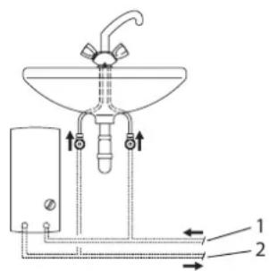
1 Cold water inlet 2 Hot water outlet pipe
Installation above the sink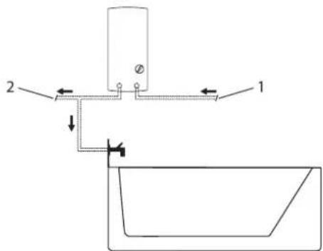
26.02.02.1344
1 Cold water inlet 2 Hot water outlet pipe

Note
Mount the device on the wall. The wall must have sufficient load-bearing capacity.
9.2 Water connection work
Installation of a safety valve is not required. Carefully flush the water supply system. It is necessary to ensure that the volume flow (see chapter "Installation/Technical data/Parameter table") is sufficient for the device to be switched on. If the volume flow value is not reached, the volume flow limiter must be adjusted (see chapter "Installation/Installing the volume flow limiter"). If, with the draw-off valve fully open, the required volume flow value is not reached, the pressure in the water supply main must be increased.
Mixer
Use low-pressure mixers. The use of high-pressure mixers is prohibited.

Note
To reduce the flow rate, it is forbidden to use shut-off valves or supply of cold water! The shut-off valve serves to lock the device.
Permitted materials for water pipes
Pipework for the water connection: galvanized steel, stainless steel, copper or plastic. Pipework for the water supply: pipe made of stainless steel and steel, copper or plastic.

Material for pipes
When using plastic pipes, the maximum temperature and maximum permissible pressure must be taken into account (see chapter "Installation / Technical data / Parameter table").
Flexible hoses for water supply
When connecting the device with flexible hoses, it is necessary to prevent twisting of the union nuts and pipe bends. Secure the hose wall, fixing it from below with two additional screws.
10. Installation
10.1 Standard installation
From above, hidden wiring for concealed installation of the DDLE Basis 18/21/24 water connection. Monobloc adjustment to 21 kW.
Material damage
Reduction of flow rate. It is forbidden to use a shut-off valve on the cold water supply line!
Preparing the rear wall
Material damage
If by mistake the wrong hole was drilled for the cable bushing, a new rear wall must be used!
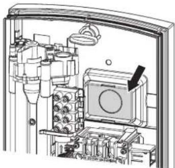
D0000041893
» Drill a hole in the rear wall for the cable bushing. If there are sharp edges, deburr them with a file.
Installing the appliance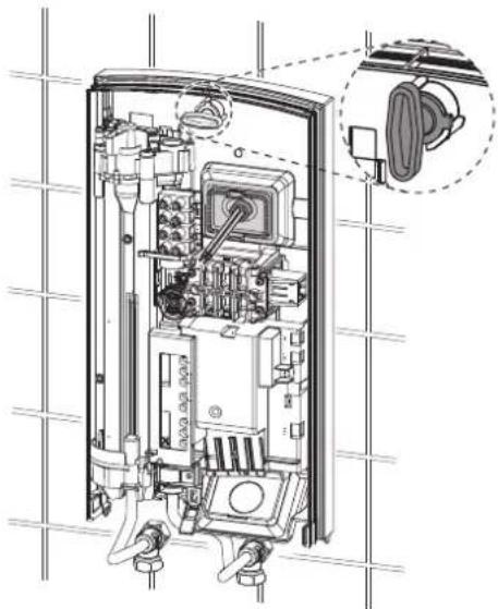
D0000041894
》Place the rear wall and the cable bushing. Insert the cable bushing with pliers into the retainer on the rear wall so that both retainers engage with the visible ring.
Remove the protective caps from the pipe connections before connecting the water. Fit the supply line tightly to the wall. Secure the retaining screw by turning it right to 90°.
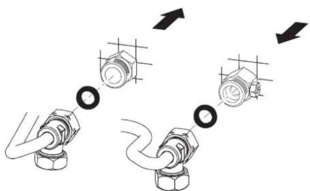
Connect the pipes with flat seals to the double nipples.
Material damage
! For the appliance to work, installation of a sieve filter is necessary.
Before using the device, check the presence of the mains fuse (see chapter "Installation / Technical service").
Dismantling / replacement of the flow rate limiter

Warning
Use of thermostatic valves: dismantling the flow rate limiter is prohibited.
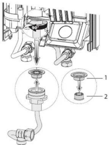
36-02-02-07
1 Plastic spring plate 2 Flow rate limiter. Remove the flow rate limiter. Install the plastic spring plate in place.
Model DDLE Basis 18/21/24 Replacement of the flow rate limiter
When choosing the required power of 24 kW, the installed flow rate limiter (white) must be replaced with the flow rate limiter from the supply kit (orange, attached to the cold water pipe).
Connection to the mains

DANGER: Danger of electric shock
All work on electrical connection and installation must be carried out in accordance with the instructions.

DANGER: Danger of electric shock
Connection to the electrical network is only permitted in a non-detachable design and with a cable gland. The device must be disconnected from the mains with a contact opening of at least 3 mm on all poles.

DANGER: Danger of electric shock
Check the connection of the device to the protective conductor.

The data can be checked against the factory plate. The voltage must match the value indicated on the plate.
Connect the appliance to the mains via an omnipolar switch (see chapter "Installation/Technical characteristics/Electrical diagram").
Model DDLE Basis 18/21/24 - Power selector switch
In the as-delivered state, the power selector switch is set to the 21 kW position. To switch to another single-phase power level, the following steps must be performed:
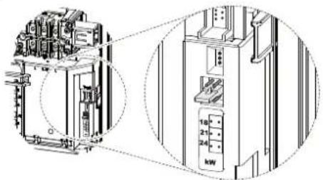
Move the power selector switch to the position corresponding to the selected power (for the power selection and the device's protective devices, see chapter "Installation/Technical characteristics/Parameter table"). Mark the selected power on the factory plate with a cross. Use a ballpoint pen for this.
Mounting the lower part of the rear panel
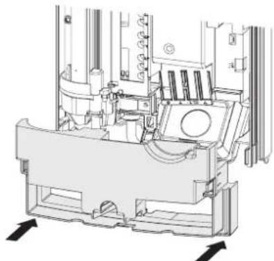
Mount the lower part of the rear panel. Secure the lower part of the rear panel.
Align the installed device by loosening the mounting screws, adjusting the electrical cable and the rear panel, and then retightening the mounting screws. If the rear panel does not fit flush against the wall, the device can be secured from below with two additional screws (see chapter "Installation/Alternative mounting options/On-wall installation, open mounting").
10.2 Alternative mounting options
10.2.1 Electrical connection from below, concealed wiring
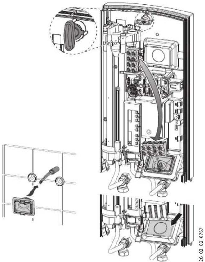
Install the cable grommet.

Material damage If an incorrect hole for the cable grommet was drilled by mistake, a new rear panel must be used!
Insert the cable gland into the hole in the rear panel. If there are sharp edges, protect them with a grommet.
Disconnect the device from the power supply before mounting the rear panel on the wall and cable gland. Insert the flat cable into the cable gland and attach the cable gland to the bracket on the rear panel so that both brackets snap into place with the protruding tab. Press the cable firmly against the panel. Lock the screw collar by turning it 90° to the right.
10.2.2 Electrical connection, exposed wire

Note
With this connection method, the degree of protection of the device changes.
Change the data on the factory nameplate. Pull out the "IP 25" marking and mark the "IP 24" box with a cross. Use a ballpoint pen for this.

Material damage
If the wrong hole for the cable gland was drilled by mistake, a new rear panel must be used.
Drill the required through holes in the rear panel (see chapter Installation / Technical data / Dimensions and connections). If there are sharp edges, protect them with a grommet.
Route the power cable through the cable gland and connect this cable to the terminal block of the mains.
10.2.3 Connection of the load shedding relay
The load shedding relay in the electrical distribution device must be used together with other electrical appliances, for example, with electric storage water heaters. Load shedding is carried out by the operation of the water heater.

Material damage
Connect the device on which the load shedding relay is installed to the terminal block of the mains in the device (see chapter Installation / Technical data / Electrical connection diagrams).
10.2.4 Installation under the sink, water connection pipes from above
For mounting the device under the sink with top pipe connections and water connection, use the mounting kit. Carefully make the through holes for the pipes, then install the pipes from the kit.
10.2.5 CONNECTION TO WATER SUPPLY FOR OPEN MOUNTING

Note
With this connection method, the device's back panel will change.
Change the data on the factory nameplate. Pull out the "IP 25" marking and mark the "IP 24" box with a cross. Then use the ball handle.
26
To close the openings for concealed mounting, install the plugs with seals. Perform the installation according to the appropriate mixer pressure.
2006 2007 2008
Insert the lower part of the back panel into the surface part and snap it in. Connect the pipes to the device. Secure the back panel by screwing it from below with two mounting screws.

Material damage
If by mistake the wrong hole for the cable ducts was made, a new back panel must be used!
Carefully break out the through holes in the device cover. If sharp edges are present, protect them with a grommet.
Push the lower part of the back panel under the pipes of the mixer connection and fix the lower part of the back panel. Connect the pipes to the device.
10.2.6 Working with preheated water
When installing central thermostatic valves, the maximum supply temperature is limited.
10.2.7 Temperature limiter

Carefully
During operation, using a preheated device may be ineffective. In this case, the limiter is set by the central thermostatic valve.
On the inside of the device cover, a temperature limit of 43 °C can be set.
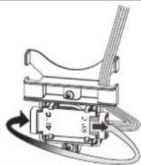
Connect the plug of the locking device to the temperature limiter set to 43 °C.
After setting the temperature limiter, the temperature selection is only possible in the range from 0 to 43 °C.
10.3 Completion of installation
Open the shut-off valves in the double pipe or in the cold water supply pipeline.
11. Commissioning

WARNING: Risk of electric shock
The device may only be put into operation by a specialist, provided that the safety regulations are observed.
11.1 Initial commissioning
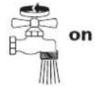
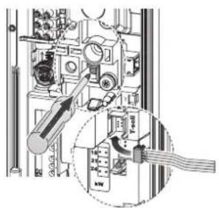
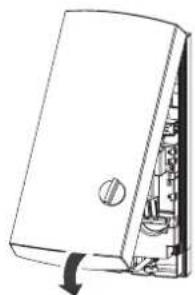
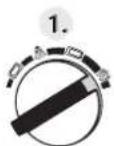
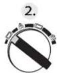
Open and close all connected draw-off valves several times until all air has escaped from the water pipes and the device. Check for leaks. Activate the pressure relief valve by firmly pressing the release button (the pressure relief valve is supplied in the deactivated state). Connect the temperature regulator plug to the electronics unit. Install the device cover. The device cover must be secured with the latch. Check the position of the device cover. Apply the mains voltage. Perform temperature calibration. Turn the temperature regulator to the right and left as far as it will go.
building 2
129343 Moscow
Tel. 0495 7753889
Fax 04957753887
Switzerland
STIEBEL ELTRON AG
Industrie West
Gass 8
5242 Lupfig
Tel. 056 4640-500
Fax 0564640-501


- INSTALLATION
- GUARANTEE
- ENVIRONMENT AND RECYCLING
- SPECIAL INFORMATION
- OPERATION
- GENERAL INFORMATION
- NOTE
- SAFETY INSTRUCTIONS
- STRUCTURE OF SAFETY INSTRUCTIONS
- KEYWORD TYPE OF RISK
- SYMBOLS, TYPE OF RISK
- KEYWORDS
- OTHER SYMBOLS IN THIS DOCUMENTATION
- UNITS OF MEASUREMENT
- SAFETY
- INTENDED USE
- GENERAL SAFETY INSTRUCTIONS
- CAUTION BURNS
- WARNING INJURY
- MATERIAL LOSSES
- CE DESIGNATION
- TEST SYMBOLS
- COUNTRY-SPECIFIC APPROVALS AND CERTIFICATIONS: GERMANY
- APPLIANCE DESCRIPTION
- HEATING SYSTEM
- SETTINGS
- TEMPERATURE LIMIT
- RECOMMENDED SETTING FOR OPERATION WITH A THERMOSTATIC VALVE
- FOLLOWING AN INTERRUPTION OF THE WATER SUPPLY
- CLEANING, CARE AND MAINTENANCE
- TROUBLESHOOTING
- INSTRUCTIONS, STANDARDS AND REGULATIONS
- STANDARD DELIVERY
- ACCESSORIES
- TAP
- STOVE CONNECTION SET
- INSTALLATION ACCESSORIES
- UNIVERSAL MOUNTING FRAME
- PIPE ASSEMBLY FOR UNDERSINK APPLIANCES
- PIPE ASSEMBLY FOR OFFSET INSTALLATION
- PIPE ASSEMBLY FOR REPLACING A GAS WATER HEATER
- LOAD SHEDDING RELAY (LR 1-A)
- ZTA 3/4 - CENTRAL THERMOSTATIC VALVE
- PREPARATIONS
- INSTALLATION SITE
- WATER INSTALLATION
- TAPS
- PERMISSIBLE WATER LINE MATERIALS
- FLEXIBLE WATER CONNECTION LINES
- STANDARD INSTALLATION
- MAKING THE WATER CONNECTION
- PREPARING THE BACK PANEL
- REMOVING / REPLACING THE FLOW LIMITER
- MAKING THE ELECTRICAL CONNECTION
- WARNING: ELECTROCUTION
- DDLE BASIS 18/21/24: RE-PLUGGING THE CODING CARD
- FITTING THE LOWER SECTION OF THE BACK PANEL
- INSTALLATION OPTIONS
- ELECTRICAL CONNECTION FROM BELOW ON UNFINISHED WALLS
- MATERIAL LOSSES: IF YOU BREAK OUT THE WRONG KNOCK-OUT BY MISTAKE, USE A NEW BACK PANEL
- ELECTRICAL CONNECTION ON FINISHED WALLS
- CONNECTING A LOAD SHEDDING RELAY
- UNDERSINK INSTALLATION, WATER CONNECTIONS - FROM ABOVE
- WATER INSTALLATION ON FINISHED WALLS
- OPERATION WITH PREHEATED WATER
- COMPLETING THE INSTALLATION
- COMMISSIONING
- INITIAL START-UP
- APPLIANCE HANDOVER
- RECOMMISSIONING
- SHUTDOWN
- MAINTENANCE
- DRAINING THE APPLIANCE
- SPECIFICATION
- WIRING DIAGRAM
- DHW OUTPUT
- PRESSURE DROP
- SIZING THE PIPEWORK
- FAULT CONDITIONS
- DETAILS ON ENERGY CONSUMPTION
- MOUNTING AND CLOSING
- SAFETY TECHNOLOGY
- CAUTION: HOT SURFACE
- WARNING: INJURY
- MATERIAL DAMAGE
- SYMBOLS
- TECHNICAL CONTROL MARK
- EURASIAN CONFORMITY
- STATE PERMITS AND CERTIFICATES: GERMANY
- DESCRIPTION OF THE DEVICE
- INSTRUCTION FOR THE DEVICE
- TEMPERATURE LIMITER
- RECOMMENDATIONS FOR SETTINGS WHEN USING THERMOSTATIC FITTINGS
- AFTER DISCONNECTING THE WATER SUPPLY
- MIXER
- CONNECTION SET FOR THE APPLIANCE
- MOUNTING ACCESSORIES
- PIPE SET FOR MOUNTING THE APPLIANCE UNDER THE SINK
- PIPE SET FOR MOUNTING WITH MIXER
- PIPE SET FOR CONVERSION TO GAS COLUMN
- RESET BUTTON (LR 1-A)
- ZTA 3/4 - CENTRAL THERMOSTAT MIXING VALVE
- PREPARATORY MEASURES
- INSTALLATION LOCATION
- WATER CONNECTION WORK
- PERMITTED MATERIALS FOR WATER PIPES
- MATERIAL FOR PIPES
- FLEXIBLE HOSES FOR WATER SUPPLY
- PREPARING THE REAR WALL
- DISMANTLING / REPLACEMENT OF THE FLOW RATE LIMITER
- WARNING
- CONNECTION TO THE MAINS
- DANGER: DANGER OF ELECTRIC SHOCK
- MODEL DDLE BASIS 18/21/24 - POWER SELECTOR SWITCH
- MOUNTING THE LOWER PART OF THE REAR PANEL
- ALTERNATIVE MOUNTING OPTIONS
- ELECTRICAL CONNECTION FROM BELOW, CONCEALED WIRING
- MATERIAL DAMAGE IF AN INCORRECT HOLE FOR THE CABLE GROMMET WAS DRILLED BY MISTAKE, A NEW REAR PANEL MUST BE USED
- ELECTRICAL CONNECTION, EXPOSED WIRE
- CONNECTION OF THE LOAD SHEDDING RELAY
- INSTALLATION UNDER THE SINK, WATER CONNECTION PIPES FROM ABOVE
- CONNECTION TO WATER SUPPLY FOR OPEN MOUNTING
- WORKING WITH PREHEATED WATER
- CAREFULLY
- COMPLETION OF INSTALLATION
- WARNING: RISK OF ELECTRIC SHOCK
- INITIAL COMMISSIONING
- SWITZERLAND
Brand : AEG
Model : DDLE Basis 27
Category : Boiler