Sense 203 - Heating DOVRE - Free user manual and instructions
Find the device manual for free Sense 203 DOVRE in PDF.
| Product type | Wood stove |
| Brand | DOVRE |
| Model | Sense 203 |
| Nominal power | 7 kW |
| Fuel | Wood (max. length 33 cm, max. humidity 20 %) |
| Energy efficiency | 80 % |
| Weight | 105 - 125 kg |
| Chimney connection diameter | 150 mm |
| Minimum required draft | 12 Pa |
| Flue gas temperature (at outlet) | 351 °C |
| CO emission (at 13 % O₂) | 0.07 % |
| Dust emission | 25 mg/Nm³ |
| Safety distance – rear (combustible materials) | 300 mm |
| Safety distance – side (combustible materials) | 500 mm |
| External air supply | Possible (kit included) |
| Glass type | Ceramic (cleanable with special product) |
| Routine maintenance | Glass cleaning, chimney sweeping, lubrication of moving parts |
| Spare parts available | Internal refractory plates, ash pan, deflector, etc. |
| Safety | Door with lock, protective glove included, prohibition of inappropriate fuels |
| First use | Burn an intense fire to cure the paint |
Frequently Asked Questions - Sense 203 DOVRE
User questions about Sense 203 DOVRE
0 question about this device. Answer the ones you know or ask your own.
Ask a new question about this device
Download the instructions for your Heating in PDF format for free! Find your manual Sense 203 - DOVRE and take your electronic device back in hand. On this page are published all the documents necessary for the use of your device. Sense 203 by DOVRE.
USER MANUAL Sense 203 DOVRE
Installiecondities 6
Algemeen 6
Schoorsteen 6
Performance declaration 4
Safety 6
Installation requirements 6
General 6
Chimney (flue). 6
Ventilation of the area 7
Floors and walls.7
Product description 8
Installation 9.
General preparation 9
Preparing the connection to the flue 10
Preparing the outside air connection 11
Installing and connecting 11
Use 12
First use 12
Fuel 12
Lighting 12
Burning wood 13
Controlling combustion air 14
Extinguishing the fire 15
Removing ashes 15
Fog and mist 15
Solving problems 15
Maintenance 16
Chimney 16
Cleaning and other regular maintenance activities 16
Sense spare parts. 18
Appendix 1: Technical data. 19
Appendix 2: Dimensions. 20
Appendix 3: Distance from combustible
material 24
Appendix 4: Diagnosis diagram 27
Index 28
Introduction
Dear user,
In buying this DOVRE heating appliance, you have chosen a high quality product. This product is part of a new generation of energy-efficient and environmentally-friendly heating appliances. These appliances make optimum use of convection heat as well as thermal radiation (radiant heat).
- Your DOVRE appliance has been manufactured with state-of-the-art production equipment. In the unlikely event of a malfunction, you can always rely on DOVRE for support and service.
The appliance should not be modified; please always use original parts.
The appliance is intended for use in a living room. It should be connected hermetically to a well-functioning chimney.
We advise you have the appliance installed by an authorized and competent installer.
DOVRE cannot be held liable for any problems or damage resulting from incorrect installation.
Observe the following safety regulations when installing and using the appliance.
In this manual, you can read how the DOVRE heating appliance can be installed, used and maintained safely. Should you require additional information or technical data, or should you experience an installation problem, please first contact your supplier.
© 2013 DOVRE NV
Performance declaration
In accordance with construction products regulation 305/2011
No. 032-CPR-2013
- Unique identification number of the product type:
Sense 7 kW
- Type, batch or serial number or other form of identification for the construction product, as scribed in article 11, subsection 4:
Unique serial number.
- Intended use for the construction product, in accordance with the applicable harmonised techr specification, as specified by the producer:
Stove for solid fuel without production of warm water in accordance with EN 13240.
- Name, registered trade name or registered trademark and contact address of the producer, as scribed in article 11, subsection 5:
- If applicable, name and contact address for the authorised whose mandate covers the tasks cified in article 12, subsection 2:
-
- The system or systems for the assessment and verification of the performance durability of construction product, specified in appendix V:
System 3
- If the performance declaration concerns a construction product that falls under a harmonised
The appointed KVBG instance, registered under the number 2013, has performed a type test under system 3 and has issued the test report no. H20130112.
- If the performance declaration concerns a construction product for which a European technical assessment is issued:
9. Declared performance:
| The harmonised norm EN 13240:2001/A2 ;2004/AC :2007 | |
| Essential characteristics Performance Wood | |
| Fire safety | |
| Fire resistance A1 | |
| Distance from combustible material | Minimum distance in mmRear: 300Side: 500 |
| Risk of glowing particles falling out Conform | |
| Emission of combustion products CO: 0.07% (13%O 2) | |
| Surface temperature | Conform |
| Electrical safety | - |
| Ease of cleaning | Conform |
| Maximum operating pressure | - |
| Flue gas temperature at nominal output | 274 °C |
| Mechanical resistance (weight carry of chimney) | Not determined |
| Nominal output | 7 kW |
| Efficiency | 80.0 % |
- The performance of the product described in points 1 and 2 conform with the performance in point 9.
This performance declaration is supplied under the exclusive responsibility of the producer specifi in point 4:
01/10/2013 Weelde
Tom Gehem CEO
Due to continuous product improvement, the supplied appliance specifications may vary from the description in this brochure without prior notice having been given.
DOVRE N.V.
Please note: All safety regulations must be complied with strictly.
Please read carefully the instructions supplied with the appliance for installation, use and maintenance before using the appliance.
The appliance must be installed in accordance with the legislation and requirements applicable in your country. Installation requirements
All local regulations and the regulations relating to national and European standards must be General observed when installing the appliance. The applic
The appliance must be connected tightly to a wellfunctioning chimney. The appliance should preferably be installed by an authorised installer. Installers will be aware of the applicable regulations and requirements. For the connection measurements: see the appendix "Technical data".
The appliance is designed for heating purposes. All surfaces, including the glass and connecting tube, can become very hot (over 100^ ! When operating, use a so-called "cold hand" or an oven glove.
Make sure there is sufficient protection if young children, disabled persons or old people The flue or chimney is needed for are in the vicinity of the appliance.
Safety distances from flammable materials must be strictly adhered to. As the warm air in the flue or chimney is light than the outside air, it rises
Do not place any curtains, clothes, laundry or other combustible materials on or near the appliance. Air intake, needed for the combustion of fuel in the
When in use, do not use flammable or explosive substances in the vicinity of the appliance. Damage caused by smoke emissions into the room is
Avoid chimney fires by having the chimney not covered by the warranty. swept regularly. Never burn wood with the door Do not connect multiple appliances (such as a open.
In the event of a chimney fire: close all the unless local or national regulations allow this. appliance's air inlets and alert the fire service. In the event of two connections ensure that the
If the glass in the appliance is broken or cracked, it must be replaced before the stove can be used again. Ask your installer for advice regarding the flue. Refer
The appliance must be connected tightly to a well-by functioning chimney.
s. For the connection measurements: see the appendix "Technical data".
- Ask the fire brigade and/or your insurance company about any specific requirements and regulations.
- Removal of combustion gases via natural draught.
As the warm air in the flue or chimney is lighter than the outside air, it rises.
Air intake, needed for the combustion of fuel in the appli- appliance.
A poorly-functioning flue or chimney can cause smoke to escape into the room when the door is opened.
^e Damage caused by smoke emissions into the room is not covered by the warranty.
Do not connect multiple appliances (such as a boiler for central heating) to the same flue, unless local or national regulations allow this. In the event of two connections ensure that the difference in height between the connections is no less than 200~mm .
Ensure that there is adequate ventilation in the room in which the appliance is installed. If ventilation is insufficient, combustion will be incomplete whereby in toxic gases can spread through the room. See the chapter "Installation requirements" for more information on ventilation.
Installation requirements
General
Chimney (flue)
Ask your installer for advice regarding the flue. Refer to the European norm EN13384 for a correct calculations for the flue.
The flue must satisfy the following requirements:
The flue or chimney must be made of fire-resistant material, preferably ceramics or stainless steel.
The flue or chimney must be airtight and well-cleaned and guarantee sufficient draught.
i
A draught/vacuum of 15 - 20 Pa during normal operation is ideal.
Starting from the flue spigot, the flue must run vertically as possible. Changes in direction and horizontal pieces disrupt the outward flow of combustion gases and may cause soot deposits.
To prevent combustion gases from cooling down too much, which reduces the draught, ensure that the interior diameter is not too big.
The flue or chimney should ideally have the same diameter as the connection collar.
i
For the nominal diameter: see the appendix "Technical data". If the smoke channel is well insulated, the diameter may be slightly bigger (up to 2x the section of the connection collar)
The section (area) of the smoke channel must be constant. Wider segments and (in particular) narrower segments disrupt the outward flow of combustion gases.
- When using a cover plate or exhaust hood : make sure that the cover does not restrict the flue outlet and that the cap does not impede the outward flue of combustion gases.
The flue must end in a zone that is not affected surrounding buildings, trees or other obstacles.
The flue outside the house must be insulated.
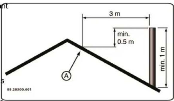
The chimney must be at least 4 metres high.
As a rule of thumb: 60cm above the ridge of the roof.
If the ridge of the roof is more than 3 metres away from the flue: stick to the measurements in the following figure. A = the highest point of the roof FI within a distance of 3 metres.
Ventilation of the area
For good combustion, the stove needs air (oxygen). This air is supplied via adjustable air inlets from the
The combustion will be incomplete in case of insufficient ventilation, which results in toxic gases being produced and spread through the area.
As a rule of thumb, the air supply should be 15cm^2 /kW Extra ventilation is needed when:
The stove is in an area that is well-insulated.
There is mechanical ventilation, for example a centakeral extraction system or an extraction hood in an ltlet open kitchen.
flow You can provide extra ventilation by having a ventilation louvre fitted on the outside wall.
Make sure that other air consuming appliances (such as tumble-driers, other heating appliances or a bathroom fan) have their own supply of outside air, or are switched off when you use the appliance.
i
You can also connect the appliance to an outside air supply. A connection kit is supplied for this purpose. This makes additional ventilation unnecessary.
Floors and walls
The floor on which the appliance is placed must have sufficient bearing capacity. For the weight of the appliance, see the appendix "Technical data".
Protect flammable flooring from heat radiation by means of a fireproof protective plate. See
the appendix "Distance from combustible material".

Remove combustible material such as linoleum, carpets/rugs and similar materials below the fireproof protective plate.

Keep sufficient distance between the appliance and combustible materials such as wooden walls and furniture.

The connecting tube also radiates heat. Ensure that there is sufficient distance or a shield between the connecting tube and combustible material.
The rule of thumb for a single-walled tube is a distance of 3x the diameter. If a lining shell is fitted around the tube, a distance of 1x the diameter is permissible.

Carpets and rugs must be at least 80 cm away from the fire.

Use a fireproof floor plate to protect a flammable floor from any ash which may fall in front of the stove. The protective plate must comply with national standards.

For the dimensions of the fireproof protective plate: see the appendix "Distance from combustible material".

For further requirements in connection with fire safety: see the appendix "Distance from combustible material".
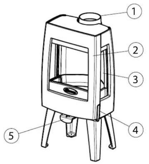
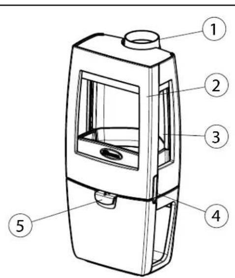
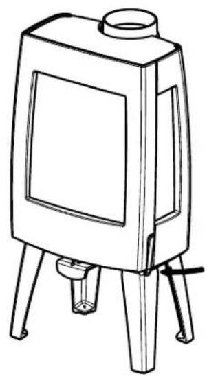
Product description
09-20021-009
09-20021-010
- Connection collar
- Door
- Side glass
- Latch
- Air slide
Door lock
The appliance is supplied with the latch button (4) installed. The door is opened by pressing in the latch button. As the latch button becomes warm during use, a glove has been supplied which you can use to protect your hand.
Installation
General preparation
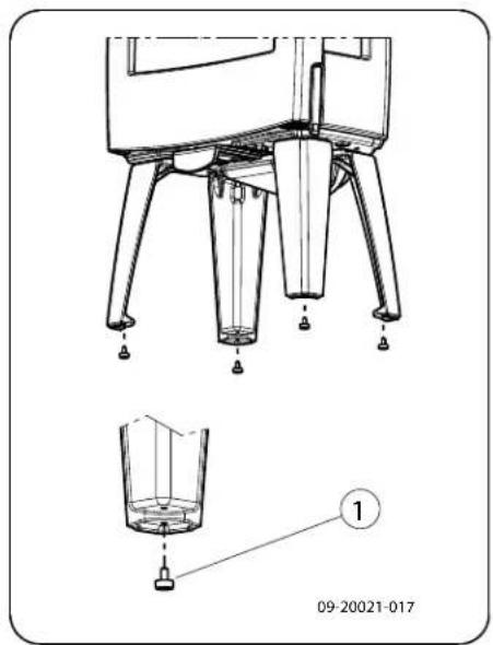
Please check the appliance immediately after delivery for damage caused during transport or any other damage or defects. The appliance is attached to the pallet with screws at the bottom.
If you detect damage caused during transport or any other damage or defects, do not use the appliance and notify the supplier.
09-20021-012
- Remove the removable parts (fire-resistant inner plates, fire grate, top plate, ash pan) from the appli. Remove the fire-resistant inner plates; see the fol- ance before you start installing the appliance. lowing figure.
It is easier to move the appliance and to avoid damage if the removable parts have been removed.
Note the location of the removable parts, so that you can re-position the parts in the correct place later on.
- Open the door; see the following figure.
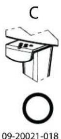
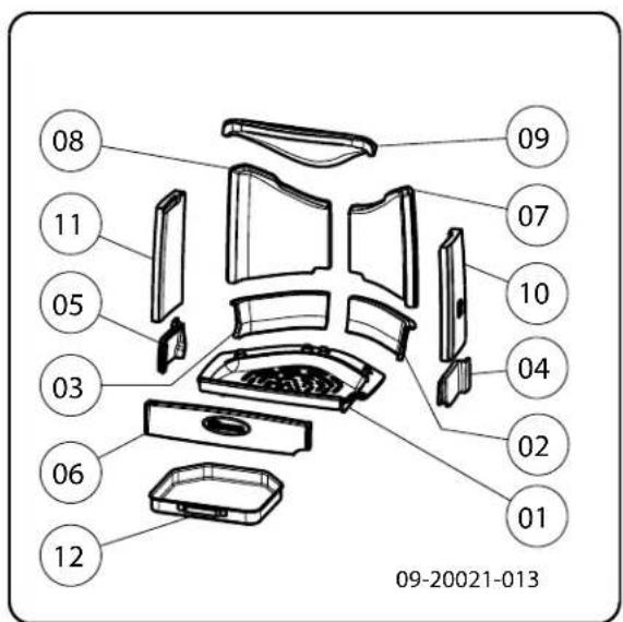
a. First remove the baffle plate (09).
The baffle plate is attached at the top with a metal clip. This is to avoid damage during transit.
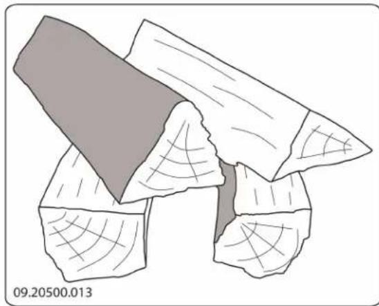
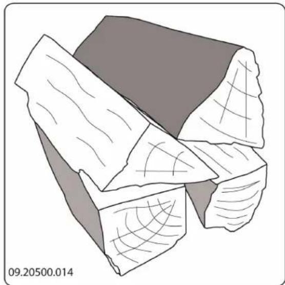
b. Remove the inner plates (10), (11), (07) and (08) at the side and at the back.
c. Remove the fire basket at the side (02) and (03) and at the front (04), (05) and (06).
d. Remove the grate and the ash pan (01) and (12).
i Vermiculite inner plates are light and tend to be ochrous in colour on delivery. They insulate the combustion chamber to boost combustion.
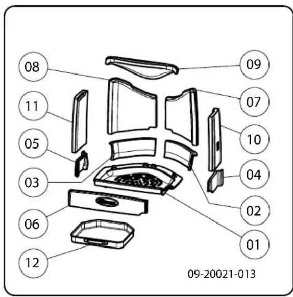
Removable internal parts
01 base plate
02 fire basket right rear
03 fire basket left rear
04 fire basket right
05 fire basket left
06 fire basket
07 side inner plate right rear
08 side inner plate left rear
09 baffle plate inner plate
10 side inner plate right
11 side inner plate left
12 ash pan
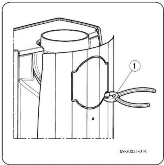
Preparing the connection to the flue
When connecting the appliance to the flue, you can choose to connect to the top or to the rear of the appliance
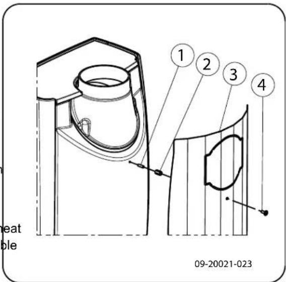
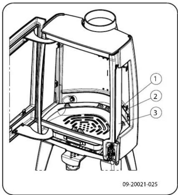
An optional heat shield is available. By using this heat shield you can reduce the distance to the combustible material. See appendix "Distance from combustible material". For a rear connection the escape plate needs to be removed. You can do this with the assist
ance of a screwdriver (1); see following figure.
Fitting the heat shield
To fit the optional heat shield, proceed as follows:
- Screw 2 M6 studs (1) with spacer (2) to the rear wall.
- Place the heat shield (3) and screw into place with 2 M6 flanged cap screws (4), see following figure.
Connecting to the top
As standard, the appliance is delivered with the connection collar fitted for a connection at the top, see following figure.
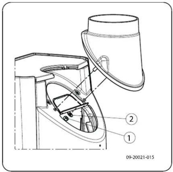
Connecting to the rear
For a connection to the rear, the position of the connection collar needs to be changed. The connection collar is attached with 2 M8 nuts (key 13). Proceeds follows:
-
First remove the baffle plate.
-
Unscrew the nuts and remove the connection col

Check that the sealing tape on the contact surface is not damaged. Replace the sealing tape if it is damaged.
- Place the connection collar turned 180^ with respect to its original position; see next figure.
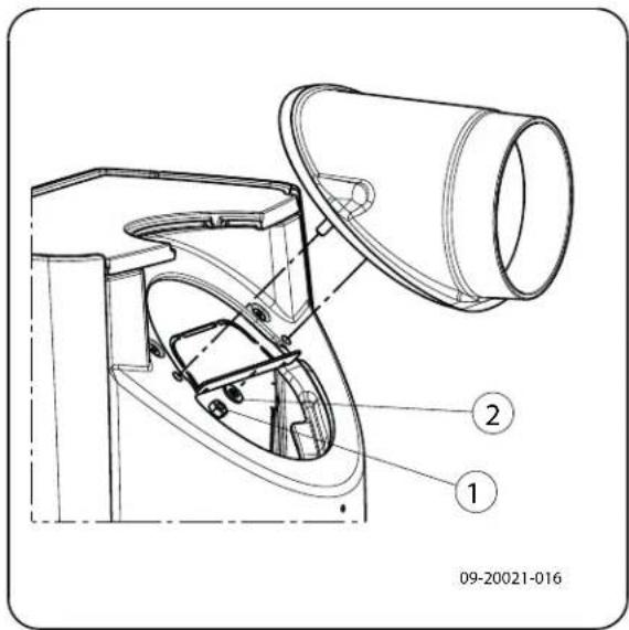
- Fit the connection collar with the 2 M8 nuts.
5 Replace the baffle plate.
Preparing the outside air connection
If the appliance is installed in a room without sufficient ventilation, you can install the connecting kit on the appliance for the supply of outside air.
The air supply tube is 100mm in diameter. If using a smooth tube, it may be no longer than 12 metres long. If accessories such as bends are used, the maximum length (12 metres)) must be reduced by 1 metre for each accessory used.
Outside air connection via the wall
- Make an opening in the wall (see the appendix, "Measurements", for the correct position of the opening).
- Close the air connection hermetically to the wall.
Installing and connecting
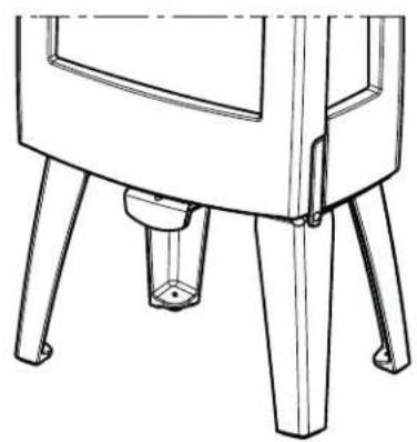
- Position the stove in the correct place, and make sure it is level. The appliance is fitted with adjustable feet so that it can be levelled.
-
Connect the stove to the flue hermetically.
-
For outside air supply connection: connect the out-Saw the wood to size and split it while it is still side air supply to the connection kit which is fitted fresh. Fresh wood is easier to split, and split wood to the appliance. dries more easily. Store the wood under a roof
-
Re-position all removed parts in the correct places in the stove.

Never use the appliance without the fire-resistant inner plates.
The appliance is now ready for use.
Use
First use
When you use the stove for the first time, make an intense fire and keep it going for a good few hours.
This will cure the heat-resistant paint finish. This may
result in some smoke and odours. You could open win by lighting a ball of paper above the baffle plate. A cold stove is located.
some smoke may escape into the room instead of up the chimney. You can avoid this problem by lighting the fire as described below.
Fuel
This stove is only suitable for burning natural wood; sawn and chopped wood that is sufficiently dry.
Do not use other fuels, as they can cause serious damage to the stove.
-
Stack two layers of medium sized logs crosswise.
-
Stack two layers of kindling crosswise on top of the logs.
-
Place a firelighter cube in the lower layer of kindling and light the cube according to the instructions on the packaging.
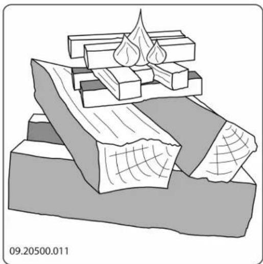
-
Close the door of the appliance and open the primary air inlet and the secondary air inlet of the appliance; see the following figure.
-
Allow the fire develop into a good blaze until there is glowing bed of charcoal. You can then add fuel and adjust the appliance, see the chapter "Stoking with wood".
o o o Primary air open (when lighting the stove)
o o Secondary air open (glass wash)
o Air for post-combustion open
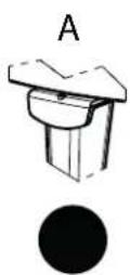
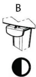
B:
o o Secondary air open (glass wash)
o Air for post-combustion open
A:
o Air for post-combustion open (never close entirely for proper combustion)
Burning wood
After you have followed the instructions for lighting :
- Slowly open the stove door.
- Spread the charcoal evenly across the bottom of the stove base.
- Stack a few logs on the charcoal.
Open stacking
If the logs are stacked openly, the wood will burn quickly as the oxygen can reach each log easily. If you want to use the stove for a short while, make open stack.
Compact stacking
Controlling combustion air
The appliance has various features for air control; see following figure.
The appliance has one air slide that regulates both the primary air and the secondary air inlet. If the air slide is completely pulled out, the primary and the secondary air inlet is open. As the air slide is pushed in, the primary air inlet and then the secondary air inlet is closed. If the air slide is completely closed, a small air vent remains open to allow for the post-combustion under the baffle plate.
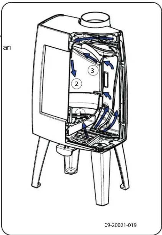
If the logs are stacked tightly, the wood will burn more slowly as the oxygen can only reach some logs easily. If you want to burn wood for a longer period, make secondary air inlet regulates the air for the glass a compact stack. (air wash) (2).
- Close the door of the appliance.
The back wall has permanent vents (3) below the baffle plate that allow for post-combustion.
- Close the primary air inlet and leave the secondary air inlet open.

Fill the appliance up to one third capacity.
Advice

Never burn wood with an open door.

Stoke the fire regularly and thoroughly.
If you frequently burn at a low setting, tar and creosote may be deposited in the flue. Tar and creosote are highly combustible substances. Thicker layers of these substances may catch fire if the temperature in the chimney increases suddenly. By burning the fire at a high intensity on a regular basis, any layers of tar and creosote will disappear. Burning at a low intensity can also cause tar to be deposited on the stove window and door. When the outside temperature is not very low, it is better to burn wood intensely for a few hours instead of having a low intensity fire for long period of time.
Control the air supply using the air vent.

The air inlet not only supplies air to the fire but to the glass as well, so that it does not quickly become dirty.
- Open the primary air inlet for the time being if supply by the secondary air inlet is inadequate you want to fan the fire.
- Topping up with a few logs regularly is better adding many logs in one go.
Extinguishing the fire
Do not add fuel and just let the fire go out. If a fire replaces the ash pan and close the door of the damped down by reducing the air supply, harmful sub-appliance.
stances will be released. For this reason, the fire should be allowed to go out naturally. Keep an eye Fog the fire until it has gone out. All air inlets can be closed
once the fire has died completely.
Removing ashes
After the wood has been burnt, a relatively small amount of ashes is left over. This bed of ashes is good insulating layer for the stove base plate and improves combustion. It is good to leave a thin lay of ashes on the stove base plate.
The flow of air through the fire plate must not be obstructed, however, and no ash may be allowed to
accumulate behind a cast-iron inner plate. Remove the excess ash regularly.
r if 1. Open the door of the appliance.
2 Use the scraper supplied to sweep the excess ash into the ash pan.
3. Using the glove supplied, remove the ash pan and empty it.
Fog and mist
Fog and mist hinder the flow of flue gases through the flue. Smoke can blow back and cause a stench. If it is not strictly necessary, it is better not to use the stove in foggy and misty weather.
Solving problems
Refer to the appendix "Diagnostic diagram" to resolve any problems in using the stove.
Maintenance
Follow the maintenance instructions in this chapter to keep the stove in good condition.
Chimney
In many countries, you are required by law to have your chimney checked and maintained.
At the beginning of the heating season: have the chimney swept by an expert.
During the heating season and after the chimney, Dirt clings less easily to well-cleaned glass. Proceed has not been used for a long time: have the chim- ney checked for soot deposits. as follows:
After the heating season: seal off the chimney with Remove dust and loose soot with a dry cloth.
1. Dirt clings less easily to well-cleaned glass. Proceed as follows:
Remove dust and loose soot with a dry cloth.

Cast-iron inner plates last a long time if you remove frequently the ash that can accumulate behind them. If accumulated ash behind the cast-iron plate is not removed, the plate will no longer be able to dissipate the heat to the surroundings and this may cause the plate to warp or crack.

Never use the stove without the fire-resistant inner plates.
Cleaning glass
- Clean the glass with stove glass cleaner:
a. Apply stove glass cleaner to a kitchen sponge, rub down the entire glass surface and give the cleaning agent time to react.
b. Remove the dirt with a moist cloth or kitchen tissue.
- Clean the glass again with a normal glass cleaning tape product.
- Rub the glass clean with a dry cloth or kitchen tissue-sieve.
Do not use abrasive or aggressive products to clean the glass.
Wear household gloves to protect your hands.

If the glass in the appliance is broken or cracked, it must be replaced before you can use the appliance again.

Make sure that no stove window cleaner runs between the glass and the cast-iron door.
Cleaning and other regular maintenance activities
Do not clean the stove when it is still warm.
Clean the exterior of the stove with a dry lint-free cloth.
You can clean the stove interior thoroughly at the of the heating season:
If necessary, first remove the fire-resistant inner plates. See the chapter "Installation" for instructions on removing and installing the inner plates.
If necessary, clean the air supply ducts.
- Remove the baffle plate at the top of the appliance and clean it.
Checking fire-resistant inner plates
The fire-resistant inner plates are consumables and subject to wear. Check the fire-resistant inner plate frequently and replace them when necessary.
See the chapter "Installation" for instructions on removing and installing the inner plates.
The insulating vermiculite or chamotte inner plates may develop hairline cracks, but this does not affect their performance adversely.
Maintenance enamelled stove
Never clean the stove while it is still hot. The most effective way to clean the enamelled surface of the stove is with a mild green soap and lukewarm water. Use as little water as possible, rub the surface dry and prevent the formation of rust. Wire wool or other abrasives should never be used. Never place a kettle directly onto an enamelled stove; use a stand to prevent damage.
Lubrication
Although cast-iron is slightly self-lubricating, you will still need to lubricate moving parts frequently.

Allow the sealant to harden fully before lighting the stove, as any moisture in the sealant will form bubbles, resulting in a new air leak.
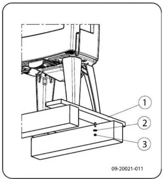
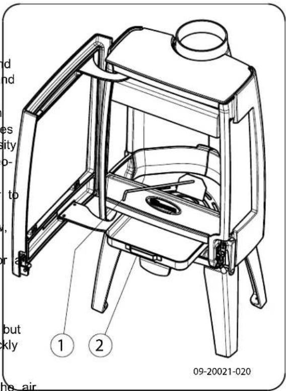
Adjust door closing
Lubricate the moving parts (such as guide systems, hinge pins, latches and air slides) with heat Check if the door closes properly. If required, the clos-resistant grease that is available in the specialisting of the door can be set looser or tighter by adjusti trade. the distance between the locking cam and the door.
Touching up damaged paint
Small areas of damaged paint finish can be touch up with a spray can of special heat-resistant paint available from your supplier.
- Open the door. The locking cam (2) is now freely and accessible; see next figure.
- Unscrew the two screws (1) with which the locking cam is attached.
Touching up the enamelled surface
Enamelling is a process carried out by traditional methods, meaning that it is possible that small colour differences and damage may occur. The appliances
By removing the packing plate (3) behind the locking cam (2), the door closes more tightly. If the door closes too tightly then insert an additional packing plate behind the locking cam.
undergo a visual inspection in the factory, that is to4. Tighten the two screws and check the closing of say, the inspector looks at the surface for a period of the door once again.
10 seconds from a distance of 1 metre.
Any damage that does not stand out is regarded as OK. A special heat-resistant paint is supplied with the stove to touch up any minor damage caused during transport.
Apply the heat-resistant paint in thin layers and leave to dry well before using the appliance.
Some enamel colours are temperature-sensitive. It can happen that the colour changes during use. The original colour will return when the stove has cooled down.
If enamelled surfaces become very hot, hairline cracks can occur. This is a normal phenomenon and has no impact on the functioning of the stove.
Ensure that the stove is not overburdened. If it does become overburdened then the surface gets very hot possibly resulting in lasting damage to the enamel.
09-20021-024
Checking the seal
Check whether the door sealing rope is still in good condition and works well. The sealing rope is subject to wear and will need to be replaced over time.
Check the appliance for air leaks. Close any chinks with stove sealant.
Replacing the glass

If the glass in the appliance is broken or cracked, it must be replaced before the stove is used again.
timeorder to replace the side glass, all the inner panels and the air guide must first be removed. The air guide is attached with a M8 nut in the middle at the top of the appliance. Proceed as follows:
- Unscrew the two glass fixings with parts (1) and (2) and remove the glass (3), see following figure
- Check the glass seal and, if necessary, fit a new sealing rope.
- Place the new glass in the grove and tighten the glass fixings.
| Pos. | Part nr. | Description | Quantity |
| 01 | 03.66544.002 | plate 1 | |
| 02 | 03.77429.002 | basket right rear | 1 |
| 03 | 03.77428.000 | basket left rear | 1 |
| 04 | 03.77425.002 | basket right | 1 |
| 05 | 03.77424.002 | basket left 1 | |
| 06 | 03.77423.002 | basket 1 | |
| 07 | 03.77523.000 | inner plate right rear | 1 |
| 08 | 03.77522.000 | inner plate left rear | 1 |
| 09 | 03.76181.000 | plate inner plate | 1 |
| 10 | 03.77525.000 | inner plate right | 1 |
| 11 | 03.77524.002 | inner plate left | 1 |
| 12 | 03.05216.000 | pan | 1 |
Sense spare parts
Appendix 1: Technical data
| Model Sense | |
| Nominal output 7.0 kW | |
| Flue connection (diameter) 150 mm | |
| Weight 105 kg - 125 kg | |
| Recommended fuel Wood | |
| Fuel property, max. length 33 cm | |
| Mass flow of flue gasses 5.1 g/s | |
| Flue gas temperature measured in the measumentation | 274°C |
| Temperature measured at appliance exit 351 °C | |
| Minimum draught 12 Pa | |
| CO emission (13%2) | 0.07 % |
| NOx emission (13%2) | 89 mg/Nm3 |
| CnHm emission (13%2) | 76 mg/Nm3 |
| Particulate emission | 25 mg/Nm3 |
| Particulate emission in accordance with NS3058-NS3059 | 2.87 g/kg |
| Efficiency | 80 % |
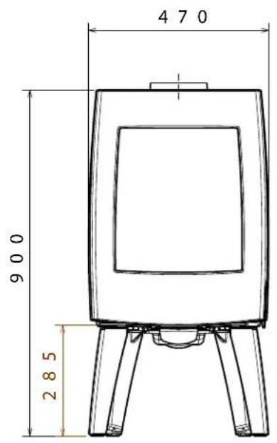
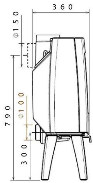
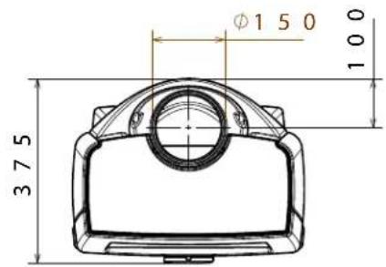
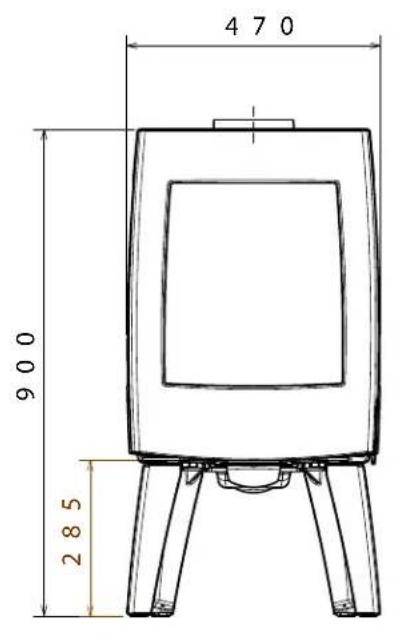
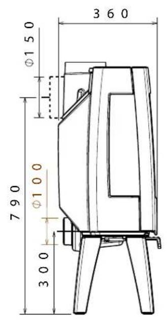
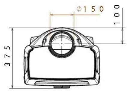
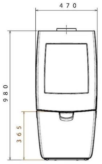
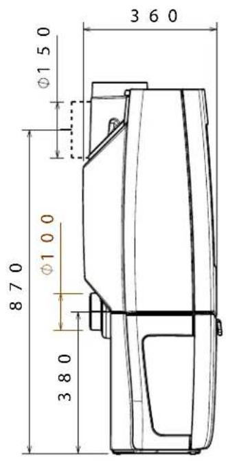
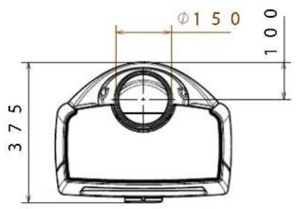
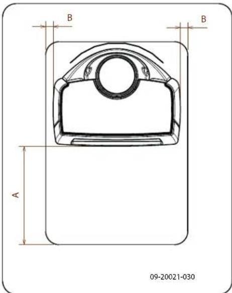
Appendix 2: Dimensions
Sense 100
09-20021-001
Sense 103
09-20021-002
Sense 200
09-20021-003
Sense 203
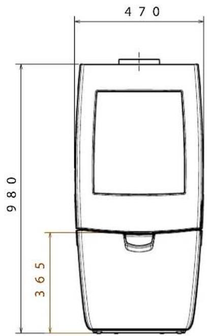
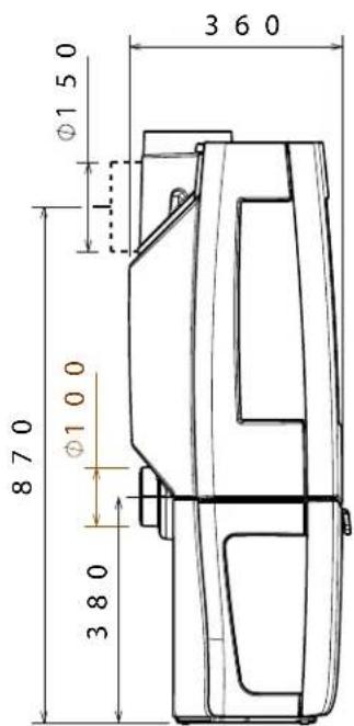
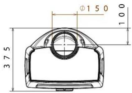
09-20021-004
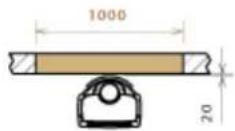
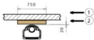
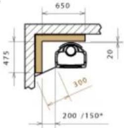
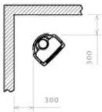
Appendix 3: Distance from combustible material
Sonata - Minimum distances in millimetres for version without heat s
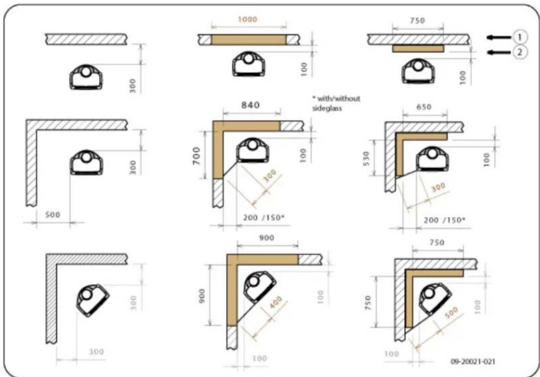
1 Combustible material
2 Indombustible material, thickness 100 mm

Please note: In order to guarantee the supply of combustion air when there is no outside air supply connection, the distance from the connection collar for the outside air to the wall must be at least 20~mm . If required, the connection collar can be removed.
Sense - Minimum distances in millimetres for version with heat shiel
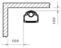
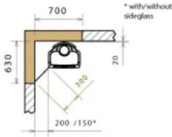
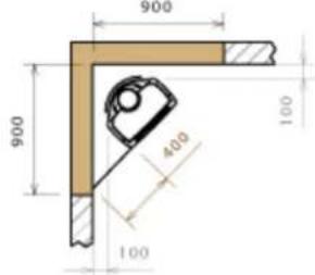
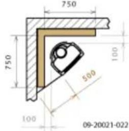
1 Combustible material
2 Indombustible material, thickness 100 mm

Please note: In order to guarantee the supply of combustion air when there is no outside air supply connection, the distance from the connection collar for the outside air to the wall must be at least 20~mm . If required, the connection collar can be removed.
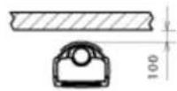
Sense - Dimensions of fireproof floor plate
Minimum dimensions of fireproof floor plate
| A (mm) | B (mm) | |
| Din 18891 500 300 | ||
| Germany 500 300 | ||
| Finland 400 100 | ||
| Norway 300 5 |
Appendix 4: Diagnosis diagram
| Problem | |||||
| ● | Wood will not stay lit | ||||
| ● | Gives off insufficient heat | ||||
| ● | Smoke emissions into the room when adding wood | ||||
| ● | Fire in stove is too intense, is hard to adjust | ||||
| Deposit on the glass | |||||
| possible cause possible | solution | ||||
| ● | ● | ● | Insufficient draught | A cold flue usually failsto create sufficient draught. Follow the instruc-tionsfor starting a fire in the 'Use' section; open a window. | |
| ● | ● | ● | Wood too damp Use wood with no more than 20%moisture. | ||
| ● | ● | ● | Logs too large | Use small piecesof kindling. Use split logs no larger than 30 cm in cir-cumference. | |
| ● | ● | ● | ● | Wood stacked incorrectly | Stackthe logs in a way that allows adequate air flow between the logs (open stacking, see "Burning wood") |
| ● | ● | ● | Chimney does not work properly | Check whether the chimney meets the requirements: at least 4 metres high, correct diameter, well-insulated, smooth inside, not too many bends, no obstructions in chimney (bird'snest, too much soot deposit), hermetically tight (no chinks). | |
| ● | ● | ● | Chimney stack incorrect Sufficiently high | high above the roof, no obstacles in the vicinity | |
| ● | ● | ● | ● | Air inlets set incorrectly Open the air | inlets completely. |
| ● | ● | ● | Stove connected to the chimney incor-rectly | Connection should be hermetically tight. | |
| ● | ● | ● | Vacuum in area in which the stove is installed | Switch off extraction systems. | |
| ● | ● | ● | Insufficient supply of fresh air | Provide an adequate air supply; if necessaryuse outside air con- nection. | |
| ● | ● | ● | Bad weather? Inversion (reversed air flow in chim- because of a high outside temperature) if required, installan extra hood on the flue to increase the draught. | ||
| ● | Draught in the living room | Avoid draught in the living room, do not place the appliance near a door or heating air ducts. | |||
| Flames touch the glass | Make sure the wood is not positioned too close to the glass. Slide the primary air inlet cover closer to the "Closed" position. | ||||
| ● | Stove is leaking air Check the door seals and stove joints. | ||||
Index
A
Adding wood
smoking stove..27.
Aerating the fire.15
Air control.14....
Air inlets.13
Air leak.17
Ash pan
open .15
Ashes
remove .15
B
Bearing capacity of floor.7
Burning
appliance is hard to adjust.27
fire is too intense. 27
insufficient heat 27
topping up fuel 15
Burning wood. 13
adding logs 13
insufficient heat. 15
C
Carpet 7
Cast iron inner plates 9
Chimney
height 7
sweep 16
Chimney fire prevention 15
Chinks in appliance. 17
Clean
glass 16
Cleaning
appliance 16
Combustible material
distance from 24
Connecting
dimensions 20
Connection collar for connection to chimney 10-11
Connection to chimney
at the rear 11
at the top. 10
rear 11
top 10
Connection to supply of outside air 11
Control of air. 14
Controlling air supply 15
Cover on flue. 7
Creosote 15
D
Damage 9
Damp wood. 12
Dimensions 20
Door adjust 17
closing 17
Locking cam
packing plate 17
open 9
sealing rope. 17
Draught 19
Drying wood. 12
E
Efficiency 5, 19
Enamel maintenance 16
External air supply connecting to..12
F
Filling height. 14
Finishing coat, maintenance 17
Fire extinguishing 15 lighting 12
Fire-resistant inner plates maintenance 16 remove 9
Fire going out. 15
Fire safety distance from combustible material. 24
floor 7
furniture 7
walls 7
Fireproof inner plates warning 12
fitting 10.
Fitting heat shield.10
Floors bearing capacity.7.. fire safety.7
Flue
connecting to.12
connection diameter.19
maintenance .16
requirements .6
Flue gas temperature.5.19.
Flue gasses mass flow 19
Fog,do not burn wood 15
Fuel
adding wood 14
necessary amount. 15
suitable 12
topping up. 15
unsuitable 12
wood 12
G
Glass clean 16 cracked 17 deposit 27 replacing 17
Glass damaged 17
H
Heat shield 10
Heat, insufficient 15, 27
Hinge adjust 17
Hood on the flue 7
1
Inner plates vermiculite 9
Inner plates, fire-resistant remove 9
Installing dimensions 20
K
Kindled fire. 12
Kindling 27
L
Lighting 12
Lubricant 17
Lubricate 17
M
Maintenance
chimney 16
clean glass 16
cleaning the appliance. 16
enamel 16
fire-resistant inner plates. 16
lubrication 17
sealing .17
Mist, do not burn wood 15
N
Nominal output 15, 19
0
Particulate emission. 19
Parts, removable 9
Primary air inlet. 13
R
Removable parts 9
Removal of ashes. 15
Remove fire-resistant inner plates 9
Remove ashes. 15
Replacing glass 17
s
Screens clean 16 deposit 27
Sealing rope for door.17
Secondary air inlet 13
Smoke
on first use.12
Smoke emissions into the room.6
Smoking stove.27
Softwood .12
Solving problems 15, 27
Stacking logs.14
Storing wood.12
Stove window cleaner.16
Suitable fuel. 12
Supply of outside air. 7, 11
Sweep chimney. 16
T
Tar 15
Temperature 19
Topping up with fuel 15
U
Unsuitable fuel 12
V
Ventilation 7
connect supply of outside air. 11
rule of thumb 7
Ventilation louvre. 7
Vermiculite
fire-resistant 9.
Vermiculite inner plates 9
W
Walls
fire safety. 7
Warning
chimney fire 12, 15
chimney fires 6
fireproof inner plates. 12
flammable materials 6
glass broken or cracked 16-17
glass is broken or cracked 6
hot surface 6
requirements 6
stove window cleaner 16
terms and conditions for insurance 6
ventilation 6-7
Weather conditions, do not burn wood 15
Weight 19
Wood 12
damp 12
drying 12
right sort. 12
storing 12
will not stay lit. 27
Table des matieres
Introduction 3
Tom Gehem
Director executivo
Gas residual temperature 5, 20
Calore, insufficiente 16, 28