
WX701.2 - Grinder WORX - Free user manual and instructions
Find the device manual for free WX701.2 WORX in PDF.

| Product type | Grinder (angle grinder) |
| Brand | Worx |
| Model | WX701.2 |
| Rated voltage | 220-240 V ~ 50/60 Hz |
| Rated input power | 860 W |
| Rated speed | 12,000 rpm |
| Max. disc diameter | 125 mm |
| Disc bore | 22.2 mm |
| Threaded spindle | M14 |
| Double insulation | Yes (class II) |
| Machine weight | 2.0 kg |
| Sound pressure level (L_pA) | 90 dB(A) |
| Sound power level (L_wA) | 101 dB(A) |
| Vibrations (main handle) | 3.7 m/s² (K=1.5 m/s²) |
| Vibrations (auxiliary handle) | 5.8 m/s² (K=1.5 m/s²) |
| Anti-vibration auxiliary handle | Yes (adjustable) |
| Guard for grinding and cutting | Yes, with clamping lever |
| Spindle lock | Yes, for disc change |
| Tool-free flange INSTALOCK® | Yes (for quick change) |
| Switch | Sliding switch with lock function |
| Maintenance and cleaning | Clean with a dry cloth; keep ventilation slots clean |
| Spare parts and repairability | No user-serviceable parts |
Frequently Asked Questions - WX701.2 WORX
User questions about WX701.2 WORX
0 question about this device. Answer the ones you know or ask your own.
Ask a new question about this device
Download the instructions for your Grinder in PDF format for free! Find your manual WX701.2 - WORX and take your electronic device back in hand. On this page are published all the documents necessary for the use of your device. WX701.2 by WORX.
USER MANUAL WX701.2 WORX
natural_image
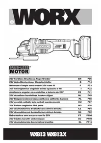
Technical line drawing of a mechanical tool or device with internal components (no text or symbols)| Angle grinder EN | P06 | |
| Winkelschleifer | D | P16 |
| Meuleuse à angle F | P27 | |
| Smerigliatrice angolare I | P38 | |
| Amoladora angular ES | P49 | |
| Haakse slijpmachine NL | P60 | |
| Szlifierka kątowa | PL | P70 |
| Kézi sarokcsiszoló gép | HU | P80 |
| Unghi polizor | RO | P91 |
| Úhlová bruska | CZ | P101 |
| Uhlová brúska SK | P110 | |
| Original instructions EN | |
| Originalbetriebsanleitung | D |
| Notice originale F | |
| Istruzioni originali I | |
| Manual original ES | |
| Oorspronkelijke gebruiksaanwijzing NL | |
| Tłumaczenie oryginalnych instrukcji PL | |
| Eredeti használati utasítás HU | |
| Traducerea instructiunilor initiale | RO |
| Překlad původních pokynů | CZ |
| Preklad pôvodných pokynov | SK |

natural_image
Completely dark image with no visible content, text, or symbols.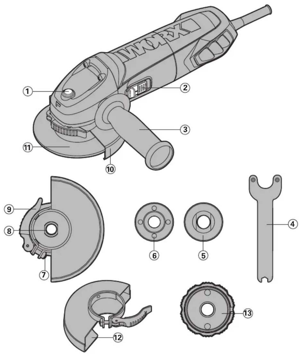
natural_image
Diagram of a mechanical device with a tool and directional arrow indicating motion (no text or symbols)A
natural_image
Mechanical assembly diagram showing a motor and gear mechanism (no text or symbols)B
natural_image
Technical line drawing of a mechanical component with no visible text or symbolsC1
C2
natural_image
Mechanical component diagram showing a rotating disc and housing (no text or symbols)C3
natural_image
Mechanical component diagram showing a valve or connector with an arrow indicating direction (no text or symbols present)D
E
- SPINDLE LOCK BUTTON
- ON/OFF SWITCH
- ANTI-VIBRATION AUXILIARY HANDLE
- SPANNER
- INNER FLANGE
- OUTER FLANGE
- CLAMP ADJUSTMENT NUT
- SPINDLE
- GUARD CLAMPING LEVER
- WHEEL GUARD FOR GRINDING
- DISC*
- WHEEL GUARD FOR CUTTING*
- INSTALOCK® TOOL-LESS FLANGE* (FOR WX701.2 WX702.1 WX707.1)
TECHNICAL DATA
Type WX700 WX701 WX701.1 WX701.2 WX702 WX702.1 WX702.2 WX707 WX707.1 (700-749-designation of machinery, representative of angle grinder)
| WX700 | WX701WX701.1 WX701.2 | WX702WX702.1 WX702.2 | WX707WX707.1 | |
| Voltage 220-240V~50/60Hz | ||||
| Power input 860W 710W 710W 860W | ||||
| Rated speed 12,000/min | ||||
| Disc size 100mm | 115m | 125m | 125mm | |
| Disc bore | 16mm | 22.2mm | 22.2mm | 22.2mm |
| Spindle thread | M10 | M14 | M14 | M14 |
| Protection class | ☐ /II | |||
| Machine weight | 2.0kg | |||
NOISE INFORMATION
| A weighted sound pressure | L_pA : 90dB(A) |
| A weighted sound power | L_wA : 101dB(A) |
| K_PA & K_WA : | 3.0dB(A) |
| Wear ear protection when sound pressure is over | 80dB(A) |
VIBRATION INFORMATION
| Vibration total values (triax vector sum) determined according to EN 60745: | |
| Typical weighted vibration | Vibration emission value a_h=3.7m/s^2 (for main handle)Vibration emission value a_h=5.8m/s^2 (for auxiliary handle) |
| Uncertainty K=1.5m/s2 | |
The declared vibration total value may be used for comparing one tool with another, and may also be used in a preliminary assessment of exposure.

WARNING: The vibration emission value during actual use of the power tool can differ from the declared value depending on the ways in which the tool is used dependant on the
following examples and other variations on how the tool is used:
How the tool is used and the materials being cut.
The tool being in good condition and well maintained.
The use the correct accessory for the tool and ensuring it is sharp and in good condition.
The tightness of the grip on the handles and if any anti vibration accessories are used. And the tool is being used as intended by its design and these instructions.
This tool may cause hand-arm vibration syndrome if its use is not adequately managed.

WARNING: To be accurate, an estimation of exposure level in the actual conditions of use should also take account of all parts of the operating cycle such as the times when the tool is switched off and when it is running idle but not actually doing the job. This may significantly reduce the exposure level over the total working period.
Helping to minimise your vibration exposure risk.
Maintain this tool in accordance with these instructions and keep well lubricated (where appropriate)
If the tool is to be used regularly then invest in anti vibration accessories.
Avoid using tools in temperatures of 10^ C or less.
Plan your work schedule to spread any high vibration tool use across a number of days.
ACCESSORIES
Spanner1
Metal grinding disc 1
Auxiliary handle 1
Anti-vibration auxiliary handle (WX707 WX707.1) (See Fig. A) 1
INSTALOCK® tool-less Flange (WX701.2 WX702.1 WX707.1) 1
We recommend that you purchase your accessories from the same store that sold you the tool. Use good quality accessories marked with a well-known brand name. Choose the type according to the work you intend to undertake. Refer to the accessory packaging for further details. Store personnel can assist you and offer advice.
SAFETY INSTRUCTIONS FOR ALL OPERATIONS
SAFETY WARNINGS COMMON FOR GRINDING OR ABRASIVE CUTTING-OFF OPERATIONS:
- This power tool is intended to function as a grinder, or cut-off tool. Read all safety warnings, instructions, illustrations and specifications provided with this power tool. Failure to follow all instructions listed below may result in electric shock, fire and/or serious injury.
- Operations such as sanding, wire brushing, polishing are not recommended to be performed with this power tool. Operations for which the power tool was not designed may create a hazard and cause personal injury.
- Do not use accessories which are not specifically designed and recommended by the tool manufacturer. Just because the accessory can be attached to your power tool, it does not assure safe operation.
- The rated speed of the accessory must be at least equal to the maximum speed marked on the power tool. Accessories running faster than their rated speed can break and fly apart.
- The outside diameter and the thickness of your accessory must be within the capacity rating of your power tool. Incorrectly sized accessories cannot be adequately guarded or controlled.
- The arbour size of wheels, flanges, backing pads or any other accessory must properly fit the spindle of the power tool. Accessories with arbour holes that do not match the mounting hardware of the power tool will run out of balance, vibrate excessively and may cause loss of control.
- Do not use a damaged accessory. Before each use inspect the accessory such as abrasive wheels for chips and cracks, backing pad for
cracks, tear or excess wear. If power tool or accessory is dropped, inspect for damage or install an undamaged accessory. After inspecting and installing an accessory, position yourself and bystanders away from the plane of the rotating accessory and run the power tool at maximum no-load speed for one minute.
Damaged accessories will normally break apart during this test time.
- Wear personal protective equipment. Depending on application, use face shield, safety goggles or safety glasses. As appropriate, wear dust mask, hearing protectors, gloves and workshop apron capable of stopping small abrasive or workpiece fragments. The eye protection must be capable of stopping flying debris generated by various operations. The dust mask or respirator must be capable of filtrating particles generated by your operation. Prolonged exposure to high intensity noise may cause hearing loss.
- Keep bystanders a safe distance away from work area. Anyone entering the work area must wear personal protective equipment. Fragments of workpiece or of a broken accessory may fly away and cause injury beyond immediate area of operation.
- Hold power tool by insulated gripping surfaces only, when performing an operation where the cutting accessory may contact hidden wiring or its own cord. Cutting accessory contacting a "live" wire may make exposed metal parts of the power tool "live" and shock the operator.
- Position the cord clear of the spinning accessory. If you lose control, the cord may be cut or snagged and your hand or arm may be pulled into the spinning accessory.
- Never lay the power tool down until the accessory has come to a complete stop. The spinning accessory may grab the surface and pull the power tool out of your control.
- Do not run the power tool while
carrying it at your side. Accidental contact with the spinning accessory could snag your clothing, pulling the accessory into your body.
- Regularly clean the power tool's air vents. The motor's fan will draw the dust inside the housing and excessive accumulation of powdered metal may cause electrical hazards.
15.Do not operate the power tool near flammable materials. Sparks could ignite these materials. - Do not use accessories that require liquid coolants. Using water or other liquid coolants may result in electrocution or shock.
- Your hand must hold on the handle when you are working. Always use the auxiliary handles supplied with the tool. Loss of control can cause personal injury
FURTHER SAFETY INSTRUCTIONS FOR ALL OPERATIONS KICKBACK AND RELATED WARNINGS
Kickback is a sudden reaction to a pinched or snagged rotating wheel, backing pad, brush or any other accessory. Pinching or snagging causes rapid stalling of the rotating accessory which in turn causes the uncontrolled power tool to be forced in the direction opposite of the accessory's rotation at the point of the binding.
For example, if an abrasive wheel is snagged or pinched by the workpiece, the edge of the wheel that is entering into the pinch point can dig into the surface of the material causing the wheel to climb out or kick out. The wheel may either jump toward or away from the operator, depending on direction of the wheel's movement at the point of pinching. Abrasive wheels may also break under these conditions.
Kickback is the result of power tool misuse and/or incorrect operating procedures or conditions and can be avoided by taking proper precautions as given below.
- Maintain a firm grip on the power tool and position your body and arm to allow you to resist kickback forces. Always use auxiliary handle, if provided, for maximum control over kickback or torque reaction during start-up. The operator can control torque reactions or kickback forces, if proper precautions are taken.
- Never place your hand near the
rotating accessory. Accessory may kickback over your hand.
- Do not position your body in the area where power tool will move if kickback occurs. Kickback will propel the tool in direction opposite to the wheel's movement at the point of snagging.
- Use special care when working corners, sharp edges etc. Avoid bouncing and snagging the accessory. Corners, sharp edges or bouncing have a tendency to snag the rotating accessory and cause loss of control or kickback.
- Do not attach a saw chain woodcarving blade or toothed saw blade. Such blades create frequent kickback and loss of control.
ADDITIONAL SAFETY INSTRUCTIONS FOR GRINDING AND CUTTING-OFF OPERATIONS SAFETY WARNINGS SPECIFIC FOR GRINDING AND ABRASIVE CUTTING-OFF OPERATIONS:
- Use only wheel types that are recommended for your power tool and the specific guard designed for the selected wheel. Wheels for which the power tool was not designed cannot be adequately guarded and are unsafe.
- The grinding surface of centre depressed wheels must be mounted below the plane of the guard lip. An improperly mounted wheel that projects through the plane of the guard lip cannot be adequately protected.
- The guard must be securely attached to the power tool and positioned for maximum safety, so the least amount of wheel is exposed towards the operator. The guard helps to protect operator from broken wheel fragments and accidental contact with wheel.
- Wheels must be used only for recommended applications. For example: do not grind with the side of cut-off wheel. Abrasive cut-off wheels are intended for peripheral grinding, side forces applied to these wheels may cause them to shatter.
- Always use undamaged wheel flanges that are of correct size and shape for your selected wheel. Proper wheel flanges support the wheel thus reducing the possibility of wheel breakage. Flanges for cut-off wheels may be different from
grinding wheel flanges.
- Do not use worn down wheels from larger power tools. Wheel intended for larger power tool is not suitable for the higher speed of a smaller tool and may burst.
ADDITIONAL SAFETY INSTRUCTIONS FOR CUTTING-OFF OPERATIONS ADDITIONAL SAFETY WARNINGS SPECIFIC FOR ABRASIVE CUTTING-OFF OPERATIONS:
- Do not "jam" the cut-off wheel or apply excessive pressure. Do not attempt to make an excessive depth of cut. Overstressing the wheel increases the loading and susceptibility to twisting or binding of the wheel in the cut and the possibility of kickback or wheel breakage.
-
Do not position your body in line with and behind the rotating wheel. When the wheel, at the point of operation, is moving away from your body, the possible kickback may propel the spinning wheel and the power tool directly at you.
-
When wheel is binding or when interrupting a cut for any reason, switch off the power tool and hold the power tool motionless until the wheel comes to a complete stop. Never attempt to remove the cut-off wheel from the cut while the wheel is in motion otherwise kickback may occur. Investigate and take corrective action to eliminate the cause of wheel binding.
-
Do not restart the cutting operation in the workpiece. Let the wheel reach full speed and carefully reenter the cut. The wheel may bind, walk up or kickback if the power tool is restarted in the workpiece.
-
Support panels or any oversized workpiece to minimize the risk of wheel pinching and kickback. Large workpieces tend to sag under their own weight. Supports must be placed under the workpiece near the line of cut and near the edge of the workpiece on both sides of the wheel.
-
Use extra caution when making a "pocket cut" into existing walls or other blind areas. The protruding wheel may cut gas or water pipes, electrical wiring or objects that can cause kickback.
SYMBOLS

To reduce the risk of injury, user must read instruction manual

Double insulation

Warning

Wear ear protection

Wear eye protection

Wear dust mask
This product has been marked with a symbol relating to removing electric and electronic waste. This means that this product shall not be discarded with household waste but that it shall be returned to a collection system which conforms to the European Directive 2002/96/CE. It will then be recycled or dismantled in order to reduce the impact on the environment. Electric and electronic equipment can be hazardous for the environment and for human health since they contain hazardous substances.
OPERATING INSTRUCTIONS

NOTE: Before using the tool, read the instruction book carefully.
INTENDED USE
The machine is intended for cutting, roughing and brushing metal and stone materials without using water. For cutting metal, a special protection guard for cutting (accessory) must be used.
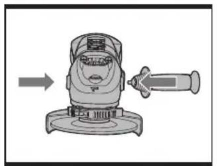
1. INSTALLING THE AUXILIARY HANDLE (See Fig. A)
You have the option of two working positions to provide the safest and most comfortable control of your angle grinder. The handle is screwed clockwise into either hole on the sides of the gear case.
Anti-vibration auxiliary handle (WX707 WX707.1)
The anti-vibration auxiliary handle reduces the vibrations, making operation more comfortable and secure.
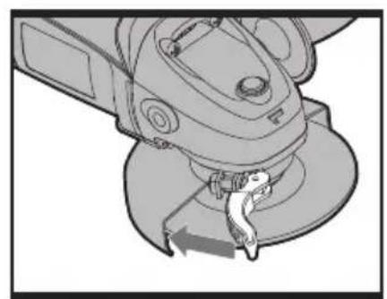
2. ADJUSTING WHEEL GUARD (See Fig. B) Before any work on the machine itself, pull the mains plug.
For work with grinding or cutting discs, the wheel guard must be mounted. Wheel Guard for Grinding
The coded projection on the wheel guard (10) ensures that only a guard that fits the machine type can be mounted.
Open the clamping lever (9). Place the wheel guard (10) with coded projection into the coded groove on the spindle of the machine head and rotate to the required position (working position).
To fasten the wheel guard (10), close the clamping lever (9).
The closed side of the wheel guard (10) must always point to the operator.
NOTE: With the clamping lever (9) open the clamp adjusting nut (7) can be adjusted to ensure the guard is securely clamped after the clamping lever (9) is finally closed.
Wheel Guard for Cutting

WARNING! For cutting metal, always work with the wheel guard for cutting(12).
The wheel guard for cutting (12) is mounted in the same manner as the wheel guard for grinding(10).
3. SPINDLE LOCK BUTTON
Clean the grinder spindle and all parts to be mounted. For clamping and loosening the grinding tools, lock the grinder spindle with the spindle lock button.
Actuate the spindle lock button only when the grinder spindle is at a standstill!
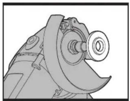
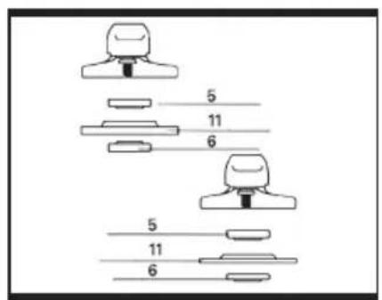
4. FITTING THE DISCS (See Fig. C1, C2, C3)
Put the inner flange onto the tool spindle. Ensure it is located on the two flats of spindle (See Fig. C1). Place the disc on the tool spindle and inner flange. Ensure it is correctly located. Fit the threaded outer flange making sure it is facing in the correct direction for the type of disc fitted. For grinding discs, the flange is fitted with the raised portion facing towards the disc. For cutting discs, the flange is fitted with the raised portion facing away from the disc (See Fig. C2). Press in the spindle lock button and rotate the spindle by hand until it is locked. Keeping the lock button pressed in, tighten the outer flange with the spanner provided. (See Fig. C3)
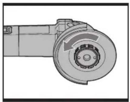
USING INSTALOCK® TOOL-LESS FLANGE (WX701.2 WX702.1 WX707.1)
Lock the grinder spindle with the spindle lock button. To tighten the INSTALOCK ^® tool-less Flange (13) firmly turn the grinding disc in clockwise direction.
A properly attached, undamaged INSTALOCK ^® tool-less Flange can be loosened by hand when turning the knurled ring in anti-clockwise direction. Never loosen a tight INSTALOCK ^® tool-less Flange with pliers. Always use the two-pin spanner.
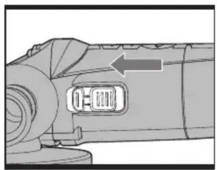
5. SLIDE ON/OFF SWITCH (See Fig. D)
To start the power tool, push the on/off switch (2) forward.
To lock the on/off switch (2), press the on/off switch (2) down at the front until it engages. To switch off the power tool, release the on/off switch (2) or, if it is locked, briefly push down the back of the on/off switch (2) and then release it.
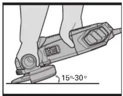
6. TO USE THE GRINDER (See Fig. E)

ATTENTION: Do not switch the grinder on whilst the disc is in contact with the workpiece. Allow the disc to reach full speed before starting to grind.
Hold your angle grinder with one hand on the main handle and other hand firmly around the auxiliary handle.
Always position the guard so that as much of the exposed disc as possible is pointing away from you.
Be prepared for a stream of sparks when the disc touches the metal.
For best tool control, material removal and minimum overloading, maintain an angle between the disc and work surface of approximately 15^-30^ when grinding.
Use caution when working into corners as contact with the intersecting surface may cause the grinder to jump or twist.
When grinding is complete allow the workpiece to cool. Do not touch the hot surface.
7. CUTTING

WARNING! For cutting metal, always work with the wheel guard for cutting.
When cutting, do not press, tilt or oscillate the machine. Work with moderate feed, adapted to the material being cut.
Do not reduce the speed of running down cutting discs by applying sideward pressure.
The direction in which the cutting is performed is important.
The machine must always work in an up-grinding motion. Therefore, never move the machine in the other direction! Otherwise, the danger exists of it being pushed uncontrolled out of the cut.
WORKING HINTS FOR YOUR ANGLE GRINDER
- Always start at no load to achieve maximum speed then start working.
- Do not force the disc to work faster, reducing the Disc's moving speed means longer working time.
- Always work with a 15-30 angle between disc and workpiece. Larger angles will cut ridges into the workpiece and affect
the surface finish. Move the angle grinder across and back and forth over the workpiece.
- When using a cutting disc never change the cutting angle otherwise you will stall the disc and angle grinder motor or break the disc. When cutting, only cut in the opposite direction to the disc rotation. If you cut in the same direction as the disc rotation the disc may push itself out of the cut slot.
- When cutting very hard material best results can be achieved with a diamond disc.
- When using a diamond disc it will become very hot. If this happens you will see a full ring of sparks around the rotating disc. Stop cutting and allow to cool at no load speed for 2-3 minutes.
- Always ensure the workpiece is firmly held or clamped to prevent movement.
MAINTENANCE
Remove the plug from the socket before carrying out any adjustment, servicing or maintenance.
There are no user serviceable parts in your power tool. Never use water or chemical cleaners to clean your power tool. Wipe clean with a dry cloth. Always store your power tool in a dry place. Keep the motor ventilation slots clean. Keep all working controls free of dust. Occasionally you may see sparks through the ventilation slots. This is normal and will not damage your power tool.
If the supply cord is damaged, it must be replaced by the manufacturer, its service agent or similarly qualified persons in order to avoid a hazard.
TROUBLESHOOTING
Although your new angle grinder is really very simple to operate, if you do experience problems, please check the following:
- If your grinder will not operate check the power at the main plug.
- If your grinder wheel wobbles or vibrates, check that outer flange is tight; check that
the wheel is correctly located on the flange plate.
- If there is any evidence that the wheel is damaged do not use as the damaged wheel may disintegrate, remove it and replace with a new wheel. Dispose of old wheels sensibly.
- If working on aluminum or a similar soft alloy, the wheel will soon become clogged and will not grind effectively.
ENVIRONMENTAL PROTECTION
This product has been marked with a symbol relating to removing electric and electronic waste. This means that this product shall not be discarded with household waste but that it shall be returned to a collection system which conforms to the European Directive 2002/96/CE. It will then be recycled or dismantled in order to reduce the impact on the environment. Electric and electronic equipment can be hazardous for the environment and for human health since they contain hazardous substances.
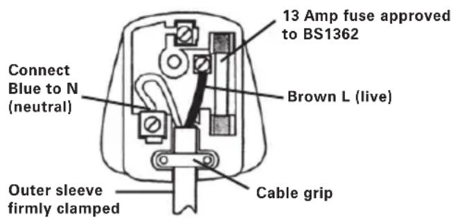
PLUG REPLACEMENT (UK & IRELAND ONLY)
If you need to replace the fitted plug then follow the instructions below.
IMPORTANT
The wires in the mains lead are colored in accordance with the following code:
bLUE = NEUTRAL
bROWN = LIVE
As the colors of the wires in the mains lead of this appliance may not correspond with the colored markings identifying the terminals in your plug, proceed as follows. The wire which is colored blue must be connected to the terminal which is marked with N. The wire which is colored brown must be connected to the terminal which is marked with L.

WARNING: Never connect live or neutral wires to the earth terminal of the Only fit an approved 13ABS1363/A plug he correct rated fuse.
NOTE: If a moulded plug is fitted and has to be removed take great care in disposing of the plug and severed cable, it must be destroyed to prevent engaging into a socket.
DECLARATION OF CONFORMITY
We,
POSITEC Germany GmbH
Declare that the product
Description WORX Angle grinder
Type WX700 WX701 WX701.1 WX701.2
WX702 WX702.1 WX702.2 WX707
WX707.1 (700-749-designation of machinery, representative of angle grinder)
Function Peripheral and lateral grinding
Complies with the following directive:
2006/42/EC
2004/108/EC
2011/65/EU
Standards conform to:
EN 55014-1
EN 55014-2
EN 61000-3-2
EN 61000-3-3
EN 60745-1
EN 60745-2-3
The person authorized to compile the technical file,
Name: Russell Nicholson
Address: Positec Power Tools (Europe)
Ltd, PO Box 152, Leeds, LS10 9DS, UK


2014/04/11
Leo Yue
POSITEC Quality Manager
Anti-vibrationshandgriff (WX707 WX707.1)
Ltd, PO Box 152, Leeds, LS10 9DS, UK
2014/04/11
Leo Yue
INFORMATIONS RELATIVES AU BRUIT
INFORMATIONS RELATIVES AUX VIBRATIONS
DÉCLARATION DE CONFORMITÉ
Nous,
POSITEC Germany GmbH
WX701.2 WX702 WX702.1 WX702.2
Ltd, PO Box 152, Leeds, LS10 9DS, UK

2014/04/11
Leo Yue
Codice WX700 WX701 WX701.1
WX701.2 WX702 WX702.1
WX702.2 WX707 WX707.1
Ltd, PO Box 152, Leeds, LS10 9DS, UK
$$ \text {leo.yue} $$

2014/04/11
Leo Yue
VEILIGHEIDSWAARSCHUWINGEN VOOR SCHURENDE SNIJBEWERKINGEN:
Type WX700 WX701 WX701.1 WX701.2
WX702 WX702.1 WX702.2 WX707
Ltd, PO Box 152, Leeds, LS10 9DS, UK

2014/4/11
Leo Yue
Mâner auxiliar anti-vibrății (WX707 WX707.1)(Fig A) 1
Flanşă de disc fără accesoriu (WX701.2 WX702.1 WX707.1) 1
1
Mâner auxiliar anti-vibrății (WX707 WX707.1)
Tip WX700 WX701 WX701.1 WX701.2
WX702 WX702.1 WX702.2 WX707
Ltd, PO Box 152, Leeds, LS10 9DS, UK

2014/4/11
Leo Yue
Manager de Calitate POSITEC
-
KNOFLÍK NA ZABLOKOVÁNÍ VŘETENA
-
VYPÍNAČ ON/OFF
-
ANTIVIBRAČNÍ PŘÍDAVNÁ RUKOJEŤ
-
PLOCHÝ KLÍČ
-
VNITŘNÍ PŘÍRUBA
-
VNĚJŠÍ PŘÍRUBA
-
NASTAVOVACÍ UPÍNACÍ MATICE
-
VŘETENO
-
UPÍNACÍ PÁKA CHRÁNIČE
-
CHRÁNIČ KOTOUČE PRO BROUŠENÍ
-
DISK*
-
CHRÁNIČ KOTOUČE PRO ŘEZÁNÍ*
-
RYCHLOUPÍNACÍ PŘÍRUBA INSTALOCK*(PRO WX701.2 WX702.1 WX707.1)
Ltd, PO Box 152, Leeds, LS10 9DS, UK


2014/4/11
Leo Yue
| ☐☐☐☐ | ☐☐☐☐☐☐☐☐☐☐☐☐☐☐☐☐☐☐☐☐☐☐☐☐☐☐☐☐☐☐☐☐☐☐☐☐☐☐☐☐☐☐☐☐☐☐☐☐☐☐☐☐☐☐☐☐☐☐☐☐☐☐☐☐☐☐☐☐☐☐☐☐☐☐☐☐☐☐☐☐☐☐☐☐☐☐☐☐☐☐☐☐☐☐☐☐☐☐☐☐ ☐☐☐☐☐☐☐☐☐☐☐☐☐☐☐☐☐☐☐☐☐☐☐☐☐☐☐☐☐☐☐☐☐☐☐☐☐☐☐☐☐☐☐☐☐☐☐☐☐☐☐☐☐☐☐☐☐☐☐☐☐☐☐☐☐☐☐☐☐☐☐☐☐☐☐☐☐☐☐☐☐☐☐☐☐☐☐☐☐☐☐☐☐☐☐☐☐☐☐☐☑☐☐☐☐☐☐☐☐☐☐☐☐☐☐☐☐☐☐☐☐☐☐☐☐☐☐☐☐☐☐☐☐☐☐☐☐☐☐☐☐☐☐☐☐☐☐☐☐☐☐☐☐☐☐☐☐☐☐☐☐☐☐☐☐☐☐☐☐☐☐☐☐☐☐☐☐☐☐☐☐☐☐☐☐☐☐☐☐☐☐☐☐☐☐☐☐☐☐☐☒☐☐☐☐☐☐☐☐☐☐☐☐☐☐☐☐☐☐☐☐☐☐☐☐☐☐☐☐☐☐☐☐☐☐☐☐☐☐☐☐☐☐☐☐☐☐☐☐☐☐☐☐☐☐☐☐☐☐☐☐☐☐☐☐☐☐☐☐☐☐☐☐☐☐☐☐☐☐☐☐☐☐☐☐☐☐☐☐☐☐☐☐☐☐☐☐☐☐☐ | |||
| Menovité napätie | 220-240V~50/60Hz | |||
| Menovitý príkon | 860W 710W 710W 860W | |||
| Otáčky na vol'nobeh | 12,000/min | |||
| Max. priemer brúsneho kotúča | 100mm 115mm 125mm 125mm | |||
| Priemer otvoru kotúča | 16mm 22.2mm 22.2mm 22.2mm | |||
| Závit vretena | M10 M14 | M14 | M14 | |
| Trieda ochrany |  | |||
| Hmotnost' náradia | 2.0kg | |||
□□□□□□□□□□□□□□□□□□□□□□□□
| Nameraný akustický tlak | L_pA : 90dB(A) |
| Nameraný akustický výkon | L_wA : 101dB(A) |
| K_PA & K_WA | 3.0dB(A) |
| Použite chrániče sluchu, ak akustický tlak presiahne | 80dB(A) |
□□□□□□□□□□□□□□□□
BEZPEČNOSTNÉ POKYNY PRE VŠETKY ČINNOSTI
BEZPEČNOSTNÉ VÝSTRAHY SPOLOČNÉ PRE ČINNOSTI BRÚSENIA A ROZBRUSOVANIA:
DOBRÉ RADY NA PRÁCU S UHLOVOU BRÚSKOU
Ltd, PO Box 152, Leeds, LS10 9DS, UK

2014/4/11
Leo Yue
- TECHNICAL DATA
- NOISE INFORMATION
- VIBRATION INFORMATION
- This tool may cause hand-arm vibration syndrome if its use is not adequately managed.
- ACCESSORIES
- SAFETY INSTRUCTIONS FOR ALL OPERATIONS
- SAFETY WARNINGS COMMON FOR GRINDING OR ABRASIVE CUTTING-OFF OPERATIONS:
- FURTHER SAFETY INSTRUCTIONS FOR ALL OPERATIONS KICKBACK AND RELATED WARNINGS
- ADDITIONAL SAFETY INSTRUCTIONS FOR GRINDING AND CUTTING-OFF OPERATIONS SAFETY WARNINGS SPECIFIC FOR GRINDING AND ABRASIVE CUTTING-OFF OPERATIONS:
- ADDITIONAL SAFETY INSTRUCTIONS FOR CUTTING-OFF OPERATIONS ADDITIONAL SAFETY WARNINGS SPECIFIC FOR ABRASIVE CUTTING-OFF OPERATIONS:
- SYMBOLS
- OPERATING INSTRUCTIONS
- INTENDED USE
- INSTALLING THE AUXILIARY HANDLE (See Fig. A)
- Anti-vibration auxiliary handle (WX707 WX707.1)
- ADJUSTING WHEEL GUARD (See Fig. B) Before any work on the machine itself, pull the mains plug.
- The closed side of the wheel guard (10) must always point to the operator.
- Wheel Guard for Cutting
- SPINDLE LOCK BUTTON
- FITTING THE DISCS (See Fig. C1, C2, C3)
- USING INSTALOCK® TOOL-LESS FLANGE (WX701.2 WX702.1 WX707.1)
- SLIDE ON/OFF SWITCH (See Fig. D)
- TO USE THE GRINDER (See Fig. E)
- CUTTING
- WORKING HINTS FOR YOUR ANGLE GRINDER
- MAINTENANCE
- Remove the plug from the socket before carrying out any adjustment, servicing or maintenance.
- TROUBLESHOOTING
- ENVIRONMENTAL PROTECTION
- PLUG REPLACEMENT (UK & IRELAND ONLY)
- IMPORTANT
- DECLARATION OF CONFORMITY
- Anti-vibrationshandgriff (WX707 WX707.1)
- INFORMATIONS RELATIVES AU BRUIT
- INFORMATIONS RELATIVES AUX VIBRATIONS
- DÉCLARATION DE CONFORMITÉ
- VEILIGHEIDSWAARSCHUWINGEN VOOR SCHURENDE SNIJBEWERKINGEN:
- Mâner auxiliar anti-vibrății (WX707 WX707.1)
- □□□□□□□□□□□□□□□□□□□□□□□□
- □□□□□□□□□□□□□□□□
- BEZPEČNOSTNÉ POKYNY PRE VŠETKY ČINNOSTI
- BEZPEČNOSTNÉ VÝSTRAHY SPOLOČNÉ PRE ČINNOSTI BRÚSENIA A ROZBRUSOVANIA:
- DOBRÉ RADY NA PRÁCU S UHLOVOU BRÚSKOU
Brand : WORX
Model : WX701.2
Category : Grinder