F — Cooker — Mode d'emploi PDF")
CP 059 MD.3 (X) F - Cooker HOTPOINT - Free user manual and instructions
Find the device manual for free CP 059 MD.3 (X) F HOTPOINT in PDF.
Frequently Asked Questions - CP 059 MD.3 (X) F HOTPOINT
User questions about CP 059 MD.3 (X) F HOTPOINT
0 question about this device. Answer the ones you know or ask your own.
Ask a new question about this device
Download the instructions for your Cooker in PDF format for free! Find your manual CP 059 MD.3 (X) F - HOTPOINT and take your electronic device back in hand. On this page are published all the documents necessary for the use of your device. CP 059 MD.3 (X) F by HOTPOINT.
USER MANUAL CP 059 MD.3 (X) F HOTPOINT
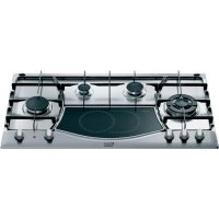
GB Mixed cooker Instructions for use and installation
flowchart
graph TD
    A["M"] --> B["Circle with curved arrow"]
    C["M"] --> D["Circle with curved arrow"]
    E["M"] --> F["Circle with curved arrow"]
    G["M"] --> H["Circle with curved arrow"]
    I["U"] --> J["Circle with dashed arrow"]
    K["H"] --> L["Circle with dashed arrow"]
    M["G"] --> N["Circle with dashed arrow"]
    O["○"] --> P["○"]
    Q["□"] --> R["□"]
    S["□"] --> T["□"]
    U["□"] --> V["□"]
    W["□"] --> X["□"]
    Y["□"] --> Z["□"]
CP 058 MT.2
flowchart
graph TD
    A["M"] --> B["●"]
    C["M"] --> D["●"]
    E["M"] --> F["●"]
    G["M"] --> H["●"]
    I["P"] --> J["□"]
    K["H"] --> L["●"]
    M["G"] --> N["○"]
    O["ARSTON"] --> P["●"]
    Q["●"] --> R["●"]
    S["●"] --> T["●"]
CP 059 MT.2 - CP 859 MT.2
flowchart
graph TD
    M1["M"] --> A["○"]
    M2["M"] --> B["○"]
    M3["M"] --> C["○"]
    M4["M"] --> D["○"]
    M5["M"] --> E["○"]
    M6["V"] --> F["○"]
    S["S"] --> G["○"]
    Z["Z"] --> H["○"]
    T["T"] --> I["○"]
    style A fill:#fff,stroke:#000
    style B fill:#fff,stroke:#000
    style C fill:#fff,stroke:#000
    style D fill:#fff,stroke:#000
    style E fill:#fff,stroke:#000
    style F fill:#fff,stroke:#000
    style G fill:#fff,stroke:#000
    style H fill:#fff,stroke:#000
    style I fill:#fff,stroke:#000
CP 057 GT - CP 857 GT
flowchart
graph TD
    M1["M"] --> A1["Circle"]
    M2["M"] --> A2["Circle"]
    M3["M"] --> A3["Circle"]
    M4["M"] --> A4["Circle"]
    M5["M"] --> A5["Circle"]
    M6["M"] --> A6["Circle"]
    P["P"] --> Box["Box"]
    H["H"] --> Box
    G["G"] --> Box
    Box --> Box1["Box"]
    Box1 --> Box2["Box"]
    Box2 --> Box3["Box"]
CP 059 MD.2
text_image
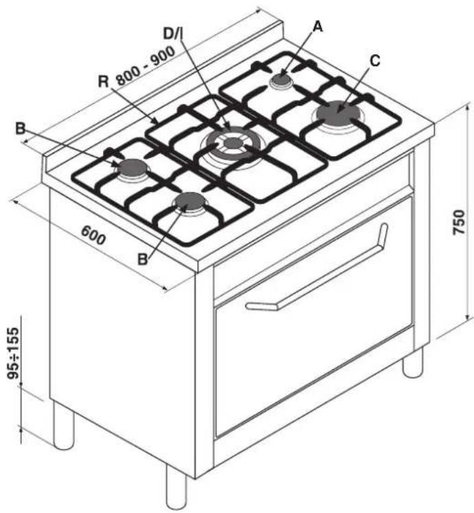
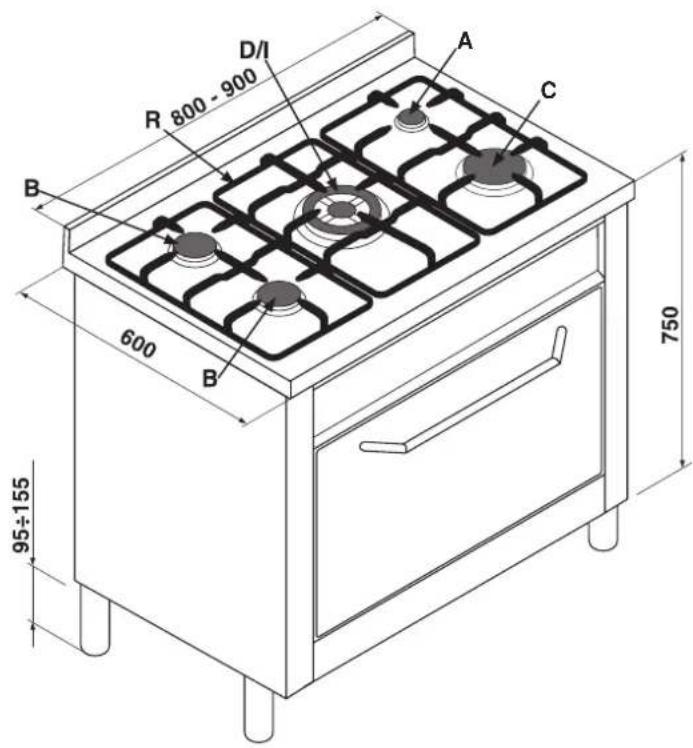
D/I R 800 - 900 A C B 600 B 750 95÷155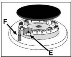
text_image
F Efig.1
natural_image
Three identical illustrations of cooking pots with crossed x marks, no text or symbols presentnatural_image
Line drawing of a hand pressing down on a kitchen appliance panel (no text or symbols)natural_image
Technical line drawing of a mechanical assembly with no visible text or symbolsfig.4
natural_image
Simple line drawing of a ladder leaning against a wall, with motion arrows indicating movement (no text or symbols)FIGURA 7
natural_image
Pure technical line drawing of a mechanical component with no text or symbolsnatural_image
Simple line drawing of three 3D cubes with one shaded and one unshaded, connected by a plane (no text or symbols)natural_image
Simple line drawing of a house interior with a stove, roof, and air vent (no text or symbols)fig.10

natural_image
Simple line drawing of a house interior with a stove, roof, and air duct (no text or symbols)text_image
Technical diagram of a mechanical component with labeled parts A through F, showing assembly or assembly steps.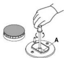
natural_image
Illustration of a hand using a tool to lift a component on a circular base, with no visible text or symbols.fig.13
natural_image
Line drawing of a hand holding a valve with a bulb, no text or symbols presentfig.14fig.12
Fig. C Fig. D
Congratulations for choosing an Ariston appliance, which you will find is dependable and easy to use. We recommend you read though this booklet for the best performance and to extend the life of your appliance. Thank you.
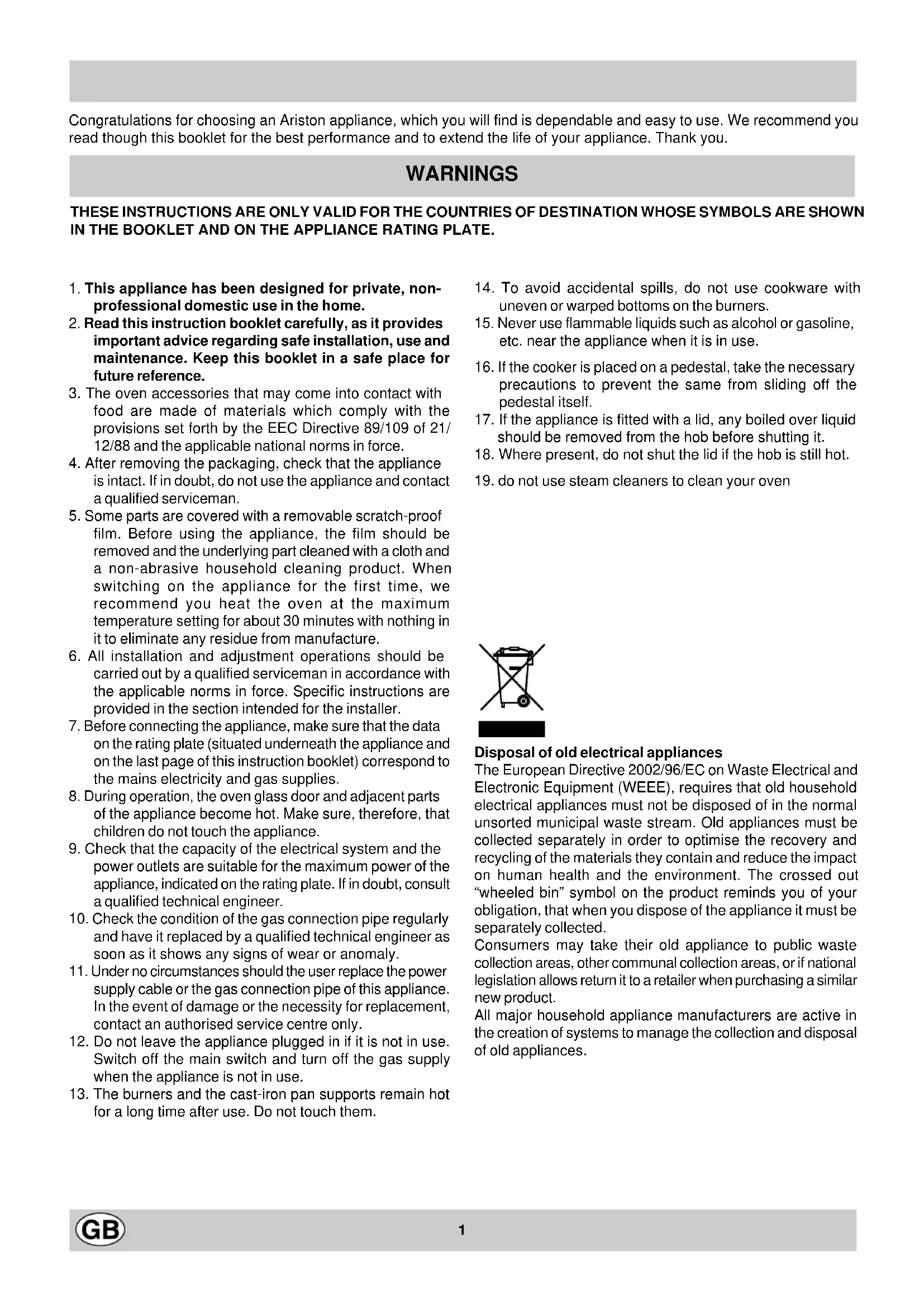
WARNINGS
THESE INSTRUCTIONS ARE ONLY VALID FOR THE COUNTRIES OF DESTINATION WHOSE SYMBOLS ARE SHOWN IN THE BOOKLET AND ON THE APPLIANCE RATING PLATE.
- This appliance has been designed for private, non-professional domestic use in the home.
- Read this instruction booklet carefully, as it provides important advice regarding safe installation, use and maintenance. Keep this booklet in a safe place for future reference.
- The oven accessories that may come into contact with food are made of materials which comply with the provisions set forth by the EEC Directive 89/109 of 21/12/88 and the applicable national norms in force.
- After removing the packaging, check that the appliance is intact. If in doubt, do not use the appliance and contact a qualified serviceman.
- Some parts are covered with a removable scratch-proof film. Before using the appliance, the film should be removed and the underlying part cleaned with a cloth and a non-abrasive household cleaning product. When switching on the appliance for the first time, we recommend you heat the oven at the maximum temperature setting for about 30 minutes with nothing in it to eliminate any residue from manufacture.
- All installation and adjustment operations should be carried out by a qualified serviceman in accordance with the applicable norms in force. Specific instructions are provided in the section intended for the installer.
- Before connecting the appliance, make sure that the data on the rating plate (situated underneath the appliance and on the last page of this instruction booklet) correspond to the mains electricity and gas supplies.
- During operation, the oven glass door and adjacent parts of the appliance become hot. Make sure, therefore, that children do not touch the appliance.
- Check that the capacity of the electrical system and the power outlets are suitable for the maximum power of the appliance, indicated on the rating plate. If in doubt, consult a qualified technical engineer.
- Check the condition of the gas connection pipe regularly and have it replaced by a qualified technical engineer as soon as it shows any signs of wear or anomaly.
- Under no circumstances should the user replace the power supply cable or the gas connection pipe of this appliance. In the event of damage or the necessity for replacement, contact an authorised service centre only.
- Do not leave the appliance plugged in if it is not in use. Switch off the main switch and turn off the gas supply when the appliance is not in use.
-
The burners and the cast-iron pan supports remain hot for a long time after use. Do not touch them.
-
To avoid accidental spills, do not use cookware with uneven or warped bottoms on the burners.
- Never use flammable liquids such as alcohol or gasoline, etc. near the appliance when it is in use.
- If the cooker is placed on a pedestal, take the necessary precautions to prevent the same from sliding off the pedestal itself.
- If the appliance is fitted with a lid, any boiled over liquid should be removed from the hob before shutting it.
- Where present, do not shut the lid if the hob is still hot.
- do not use steam cleaners to clean your oven
Disposal of old electrical appliances
The European Directive 2002/96/EC on Waste Electrical and Electronic Equipment (WEEE), requires that old household electrical appliances must not be disposed of in the normal unsorted municipal waste stream. Old appliances must be collected separately in order to optimise the recovery and recycling of the materials they contain and reduce the impact on human health and the environment. The crossed out "wheeled bin" symbol on the product reminds you of your obligation, that when you dispose of the appliance it must be separately collected.
Consumers may take their old appliance to public waste collection areas, other communal collection areas, or if national legislation allows return it to a retailer when purchasing a similar new product.
All major household appliance manufacturers are active in the creation of systems to manage the collection and disposal of old appliances.
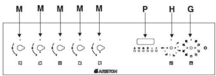
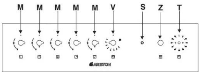
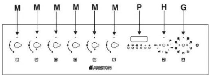
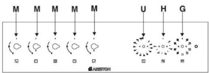
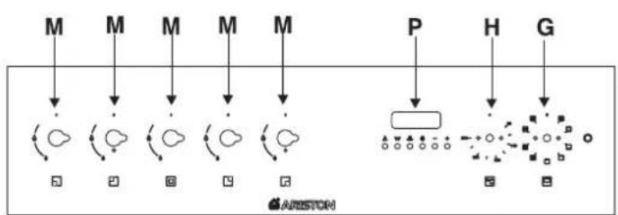
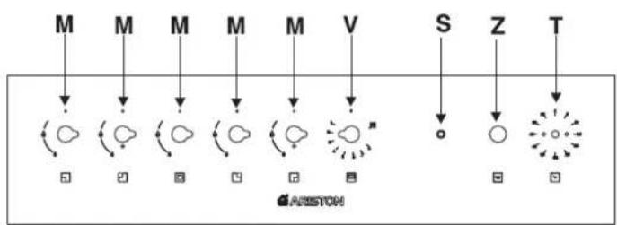
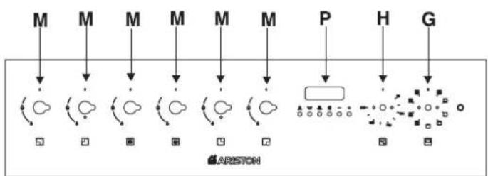
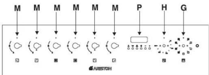
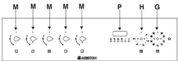
COOKER DESCRIPTION
text_image
M M M M M U H G ARISTONCP 058 MT.2
flowchart
graph TD
    M1["M"] --> A["○"]
    M2["M"] --> B["○"]
    M3["M"] --> C["○"]
    M4["M"] --> D["○"]
    P["P"] --> E["□"]
    H["H"] --> F["●"]
    G["G"] --> F
    A --> G
    B --> H
    C --> I
    D --> J
    E --> K
    F --> L
    G --> M
    H --> N
    I --> O
    J --> P
    K --> Q
    L --> R
    M1 --> S
    M2 --> T
    M3 --> U
    M4 --> V
    P --> W
    H --> X
    G --> Y
    A --> Z["AUSTON"]
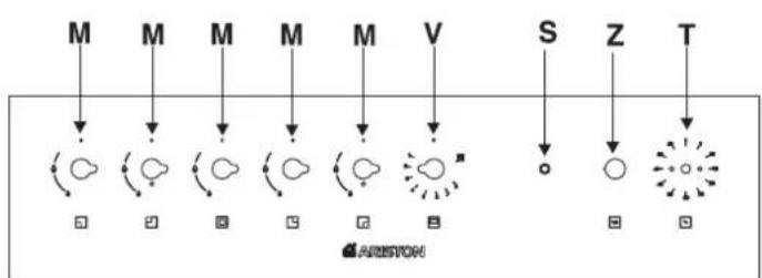
CP 059 MT.2 - CP 859 MT.2
flowchart
graph TD
    M1["M"] --> A["Circle"]
    M2["M"] --> B["Circle"]
    M3["M"] --> C["Circle"]
    M4["M"] --> D["Circle"]
    M5["M"] --> E["Circle"]
    M6["V"] --> F["Star"]
    S["S"] --> G["Circle"]
    Z["Z"] --> H["Circle"]
    T["T"] --> I["Star"]
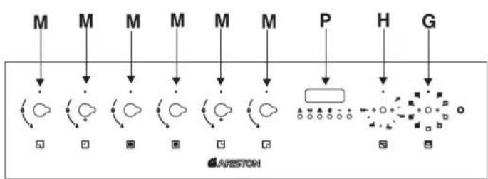
CP 057 GT - CP 857 GT
flowchart
graph TD
    M1["M"] --> A["Circle Node"]
    M2["M"] --> A
    M3["M"] --> A
    M4["M"] --> A
    M5["M"] --> A
    P["P"] --> D["Rectangle"]
    H["H"] --> D
    G["G"] --> D
    A --> C["Square"]
    C --> D
    style A fill:#f9f,stroke:#333
    style D fill:#bbf,stroke:#333
    note right of A ARISTON
CP 059 MD.2
text_image
D/I R 800 - 900 A C B 600 B 750 95÷155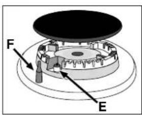
text_image
F Efig.1
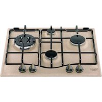
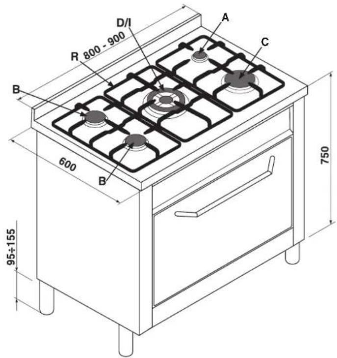
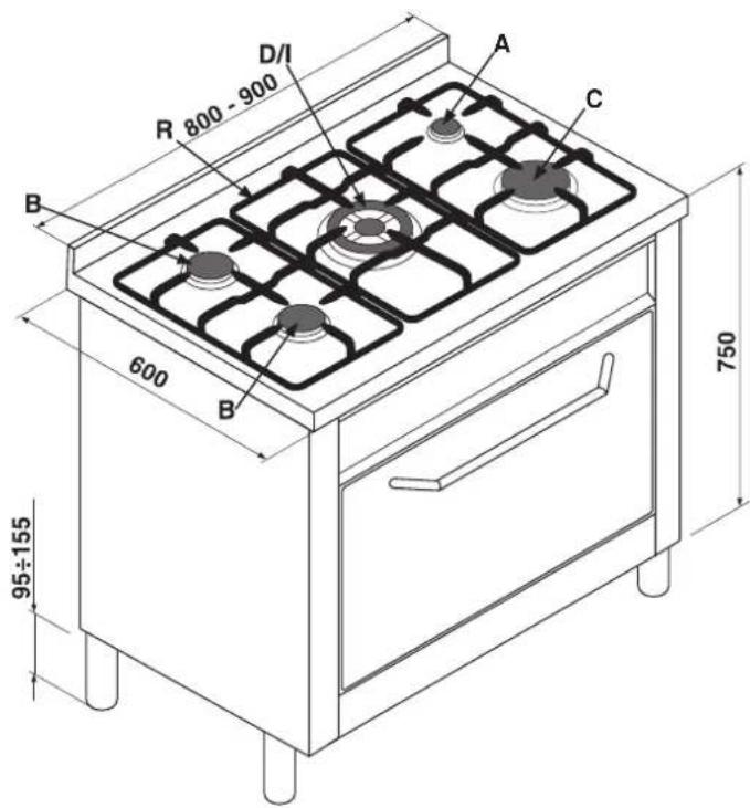
A Auxiliary gas burner
B Semi-rapid gas burner
C Rapid gas burner
D Triple ring gas burner DC-DR gas burner
E Ignitor for Gas Burners
F Safety Device - Activates if the flame accidentally goes out (spills, drafts, etc.), interrupting the supply of gas to the burner.
G Electric oven selector knob (cooking mode selection)
H Electric oven thermostat knob (temperature selection)
M Control knobs for gas burners
R Support grid for cookware
P Timer
S Electric heating element indicator light
T Minute minder
U End of cooking programmer
V Gas oven thermostat knob (gas oven mode selector with temperature adjustment and electric grill)
Z Gas oven light button
INSTRUCTIONS FOR USE
Gas burners
On the control panel, the following symbols are indicated around each knob "M" or on the knob itself: Cock
Off
High flame
Low flame
Moreover, the symbols ▪ near the knobs indicate the position of the relative burner on the hob.
The burners are fitted with a safety thermocouple device against gas leaks. This device interrupts the gas supply should the burner flame go out during operation.
To light one of the burners, proceed as follows:
- turn the relative knob anti-clockwise until the pointer is on the high-flame symbol;
- press the knob down fully to actuate the automatic gas ignition;
- keep the knob pressed down for about 6 seconds with the flame lit to allow the safety thermocouple to heat;
- release the knob, checking that the flame is stable. If it is not, repeat the operation.
For minimum power, turn the knob towards the low flame symbol. Intermediate positions are possible by simply setting the knob anywhere between the high and the low flame symbol.
Important:
- Do not actuate the automatic ignition device for more than 15 consecutive seconds.
- Difficulty in ignition is sometimes due to air inside the gas duct.
- If a burner flame accidentally goes out, the gas continues to exit for a few moments before the safety device is actuated. Turn the control knob to the off position and do not attempt ignition again for at least 1 minute, thereby letting the gas disperse, which could otherwise be a danger.
- When the appliance is not in operation, check that the knobs are set to the off position "●". The main gas supply cut-off cock should also be turned off.
Practical advice on using the burners
To obtain maximum efficiency from the burners, we recommend you only use pans with a diameter suitable for the burner being used, so that the flame does not extend beyond the pan base (see the following table).
When a liquid starts boiling, we recommend you turn the flame down just enough to keep the liquid simmering.
| Burner ø Pan Diameter (cm) | |
| A.Auxiliary | 6 – 14 |
| B.Semi-rapid | 15 – 20 |
| C.Rapid | 21 – 26 |
| D. Triple ring | 24 - 26 |
| I.Double ring DC-DR (inner) | 10 - 14 |
| I.Double ring DC-DR (outer) | 24 - 28 |
The hob is fitted with reducing pan stands, which should only be used on auxiliary burner "A" (fig.1a) and on the DC-DR (inner) "I"(fig.1b).
fig.1a
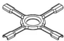
fig.1b
The "dual independent flame" burner
This gas burner consists of two concentric burner rings which can be actuated together or independently. When the two rings are used together at the highest setting, the burner reduces the length of cooking time with respect to traditional burners. The dual ring also distributes heat more evenly on the bottom of cookware, especially when both burner rings are used at the lowest setting. Cookware of any size can be used. If small pots or pans are used, only turn the inner burner on. Each burner ring has its own control knob:
the knob indicated by symbol

controls the inner ring;
the knob indicated by symbol

controls the outer ring;
To turn on one of the two rings, press the relative knob in all the way and turn it anti-clockwise to the maximum setting The burner is fitted with an electronic ignitor that is actuated automatically when the knob is pressed.
Since the burner is fitted with a safety device "F", the knob should be pressed for approximately 6 seconds for the device keeping the flame lit automatically to heat up.
To ensure that the double-flame burner is used to its full potential, never set the inside ring to minimum and the outside ring to maximum at the same time.
To turn the burner off, turn the knob clockwise until it stops (corresponding again with the “●” symbol).
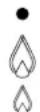
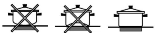
For the best performance of your burners, keep the following in mind: All types of pans can be used on the burners. The important thing is that the bottom should be completely even.
natural_image
Three identical line-drawn icons of a cooking pot with crossed x marks, no text or symbols present.The oven burner features a thermocouple safety device.
This device automatically cuts off the gas from the burner in a few seconds should the flame accidentally go out.
Lighting the oven burner
- open the oven door;
- press and turn the thermostat knob "V" (with the symbol
☐) and set it to maximum; keep it pushed.
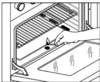
Should there not be any electric energy, hold a lighted match near the central hole on the oven bottom as in fig.3;
fig.3
natural_image
Illustration of a hand using a tool to clean or install a window with a tray (no text or symbols visible)- keep the knob pressed in for around 10 seconds;
- release the knob, checking that the flame is stable release the knob, checking that the flame is stable, and hold the door open for approximately 30-40 seconds;
- Close the oven door carefully to prevent the flame from going out;
- wait around 10-12 minutes before placing any food to be cooked into the oven, so as to preheat the oven suitably;
- set the temperature required for cooking by turning the thermostat knob to the positions ranging from 1 to 8 according to the following table:
Important: if the burner flame accidentally goes out, the gas continues to exit for a few moments before the safety device activates.
Turn the control knob to the off position and do not attempt ignition again for at least 1 minute, thereby letting the gas disperse, which could otherwise be a danger.
Electric grill operation
To grill food, turn the oven control knob clockwise to position [←]; the indicator light "S" will also come on.
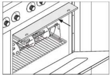
When cooking with the grill, we recommend that you keep the oven door open and that you apply the knob protection shield as indicated in figure 4.
| Position Knobs | 1 | 2 | 3 | 4 | 5678 | |||||||
| °C | 120 | 130 | 155 | 170 | 195 | 215 | 235 | 255 |
natural_image
Technical line drawing of a mechanical assembly with no visible text or symbolsfig.4
WARNING: when the grill is in operation, the surrounding parts can become very hot. Please keep children away from the cooker.
Oven light
To turn the gas oven light on, press button "Z" with the symbol

Minute minder "T"
This is a buzzer timer situated on the control panel and is suitable for timing up to a max. of 60 minutes.
Turn the knob with the symbol until the pointer is aligned with the required time.
When the set time has elapsed, a buzzer sounds (it does not turn the oven off).
It is advisable to turn the knob to 60 and then back to the time required, even if this less than 60 minutes.
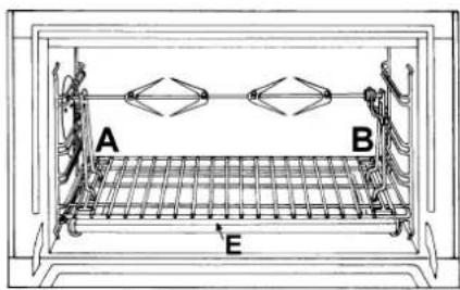
Spit - Rotisserie
This accessory is to be used exclusively when grilling food. Proceed as follows: insert the meat to be cooked along the length of the spit rod, securing it with the special adjustable forks (fig.5a).
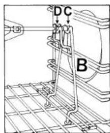
Introduce the supports "A" and "B" (fig.5b) into the holes in the drip tray "E", rest the rod groove on the seat "C" and insert the oven rack into the lowest guide of the oven; now insert the spit rod into the relative hole, moving the groove forward into seat "D". Start the grill and the rotisserie by turning the thermostat knob "G" to the position with the
symbol.
text_image
A B Efig.5a
text_image
D C Bfig.5b
MULTI-FUNCTION OVEN
The oven gives nine different heating element combinations; so the most suitable type of cooking for each dish can therefore be chosen, with convincing results.
By turning the selector knob "G" marked with the symbol , different cooking functions are obtained, as shown in the table on the right.
After having selected the cooking function, set the thermostat knob "H" marked with the symbol °C to the temperature required.
- For traditional cooking (roasts, biscuits, etc.) in conventional mode use the function □(hot above + below).
Only put the food to be cooked into the oven when it has reached the selected temperature and preferably use just one shelf for cooking.
| Symbol | Function | Power |
| 0 | 0) Off | - |
| 1) Oven light | 50 W | |
| 2) Top + Bottom heating elements | 2350 W | |
| 3) Bottom heating element | 1300 W | |
| 4) Minigrill heating element | 1050 W | |
| 5) Grill heating element | 2000 W | |
| 6) Grill heating element + fan | 2050 W | |
| 7) Top + Bottom heating elements+fan | 2400 W | |
| 8) Rear round heating element + fan | 2850 W | |
| 9) Fast defrosting | 50 W |
To provide heat only to the bottom or the top part of the dishes, turn the selector to the position (hot below), or (hot above).
- With the function ☒hot above and below + fan assistance) traditional-type cooking (hot above and below) is combined with fan assistance.
- With this function (an assisted) heat is transmitted to the foods through pre-heated air made to circulate inside the oven by a fan. The oven heats up very quickly so the food to be cooked may be put into the oven as it is switched on. Cooking is also possible simultaneously on both shelves.
- The “fast defrosting” function ☐ uses no heating elements, just the oven light and the fan.
- Grill operation: a high heat output is used for grilling, so that the surface of the food is immediately browned; this is particularly indicated for meats which should remain tender
on the inside. To grill, turn the selector knob "G" to the position [grill], (grill + fan).
During grilling, do not set the thermostat knob to over 200 °C and keep the oven door closed (not even in the monigrill mode).
Oven light
The oven light comes on automatically when the selector knob is turned to any of its positions.
Indicator light "S"
It indicates that the oven is heating up. When the light goes out, the required temperature has been reached inside the oven.
When the light alternately comes on and goes out, it means that the thermostat is working properly to maintain the oven temperature constant.
Timer "U" (mod. CP 058 MT.2)
Manual operation
Turn the timer knob with symbol anti-clockwise and
set the marker to symbol 🎨 (manual). Turn the oven on at the selector knob and set the desired temperature on the thermostat knob. To turn the oven off, turn the timer knob back to its initial position "●".
Operation with cooking time programming
Turn the timer knob clockwise, setting the marker to the desired cooking time (from 10 to 120 minutes). Turn the oven on at the selector knob and set the desired temperature on the thermostat knob. Once the countdown is over, a buzzer will sound, and will stop doing so after 1 minute or if you press any button whatsoever. Remember that the timer is deactivated when cooking starts (be it immediate or programmed).
Cooling ventilation
(CP 059 MD.2 - CP 059 MD.3 (X) F)
In order to cool down the temperature of their exterior, some models are fitted with a cooling fan that comes on when the programme selector knob "G" is turned. In this case, the fan is always on and a normal flow of air can be heard exiting between the oven door and the control panel.
(CP 059 MD.2)
In these models, the cooling fan only comes on when the oven is hot.
Once you have removed the food from the oven, we recommend you leave the oven door ajar for a few minutes: this will drastically reduce the duration of the cooling cycle. The process is controlled by an additional thermostat and can consist of one or more cycles.
TIMER (ELECTRIC OVEN)
The programmer makes it possible to preset the oven and the grill in terms of:
- delay start with a preset length of time for cooking;
- immediate start with a preset length of time for cooking;
- timer.
Button functions:
△ : Timer with hour and minutes;
1-1 : Length of cooking time;
: End cooking time;
: Manual change;
■ : Change time (backwards);
+ : Change time (forwards).
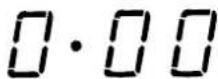
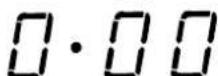
How to Reset the Digital Clock
After the appliance has been connected to the power source or following a power outage, the clock display will begin to blink and read: 0:00
- Press the buttons at the same time. Then use (within 4 seconds) the - and + buttons to set the exact time.
Use the + button to move the time forwards.
Use the - button to move the time backwards.
The time can also be changed in the following two ways:
-
Repeat all of the foregoing steps.
-
Press the 🎨 button, and then use the - and + buttons to reset the time.
Manual Operation Mode for the Oven
After the time has been set, the programmer is automatically set to manual mode.
Note: Press the button to return the oven to manual mode after every "Automatic" cooking session.
Delayed Start Time with Preset Cooking Length
The length and the end cooking times must be set. Let us suppose that the display shows 10:00.
- Turn the oven control knob to the cooking setting and temperature desired (example: convection oven at 200°C).
- Press the □ and the use (within 4 seconds) the - and + buttons to set the length of the cooking time. Let us suppose that 30 minutes was set for the length of the cooking time. In this case, the display will show:
0·30
Release the button, and within 4 seconds, the current time will reappear with the symbol and "auto."
- Press the 📄 button, and then use the - and + buttons to set the end cooking time. Let us suppose that it is 13:00
13·00
- Release the button and the display will show the current time within 4 seconds:
10·00
When "auto" is lighted, it indicates that the length and end
cooking time have been preset to operate in automatic mode. At this point, the oven will turn on automatically at 12:30 in order to finish the cooking session within 30 minutes. When the oven is on, the symbol (cooking pot) will appear on the display for the entire length of the cooking process. The button can be pressed at any time to display the setting for the length of the cooking time, while the button can be pressed to display the end cooking time.
At the end of the cooking time, an acoustic signal will sound. Press any button it turn it off (except the - and + buttons).
Immediate Start Time with Preset Cooking Length
When only the length of the cooking time is set (points 1 and 2 of the paragraph entitled, "Delayed Start Time with Preset Cooking Length"), the cooking session starts immediately.
Cancelling a Preset Cooking Time
Press the button, and use the - button to set the time to:
Then press the manual cooking mode button

Timer Feature
The timer can be used to count down from a given length of time. This feature does not control when the oven comes on or turns off, but, rather, it only emits an acoustic signal when the preset time has run out.
Press the button, and the display will read:
Then use the - and + buttons to set the desired time.
Release the button, and the timer will start at that second.
The display will show the current time.

At the end of the preset time, an acoustic signal will sound, which can be turned off by pressing any button (except the - and + buttons), and the △ symbol will turn off.
Changing and Cancelling Settings
- The settings can be changed at any time by pressing the corresponding button and using the - or + button.
- When the length setting for the cooking time is cancelled, the end cooking time setting is also cancelled, and vice versa.
- When in automatic cooking mode, the appliance will not accept end cooking times prior to the start cooking time proposed by the appliance itself.
Buzzer volume control
Once you have made and confirmed the clock settings, use button - to adjust the volume of the alarm buzzer.
Important: The appliance should be disconnected from the mains supply before starting cleaning operations.
To ensure a long life cycle for the appliance, it is essential to carry out a thorough general clean frequently, while observing the following instructions:
Inside the oven door:
Clean the surface with a cloth moistened with hot water and non abrasive liquid detergent, then rinse and dry thoroughly.
Inside the oven:(only on certain models)
- The inside of your oven is coated with a special self-cleaning microporous enamel glaze which, at a normal cooking temperature of between 200 and 300^ , oxidises and completely eliminates all grease spots or other substances that inevitably attack the inner walls of the oven. This way cleaning is kept right down to a minimum: as a matter of fact, you just need to rub the surfaces of the oven with a wet cloth regularly, after cooking, to remove the thin layer of ash that may have been deposited during cooking, in order to maintain the self-cleaning property of the oven intact.
- After cooking where liquid has overflowed or when the dirt has not been eliminated completely (for example when grilling food, and the temperatures reached are not high enough for the full self-cleaning action of the enamel to be performed), we recommend you leave the oven on at maximum temperature so that all grease residue and the like are eliminated.
- If, after long-term use, you find evident grease stains deposited on the self-cleaning oven walls, probably due to your failing to follow the above maintenance advice, clean the surfaces thoroughly with hot water and a soft cloth (do not use any detergents), then rinse and dry thoroughly.
- Do not remove any dry caked-on grease using sharp objects, as these could etch the self-cleaning coating.
- If the self-cleaning surfaces inside the oven are damaged or worn, due to incorrect or poor maintenance or after many years of use, you can request a kit of self-cleaning panels to line the inside of the oven. To order these, just contact an authorised Service Centre.
Oven exterior:
- Only clean the appliance when the oven is cold.
- The steel parts and especially the areas with the screen-printed symbols should not be cleaned with solvents or abrasive detergents. It is advisable to use only a damp cloth with lukewarm water and washing up liquid.
Stainless steel may remain stained if in long-term contact with very calcareous water or aggressive detergents
(containing phosphorus).
It is therefore always necessary to rinse and dry all surfaces thoroughly after cleaning.
Important: cleaning operations must be made horizontally, in the direction of the steel glazing.
• After cleaning, any treatments to polish the surfaces may be performed: only use specific products for stainless steel.
Important: do not use abrasive powders, aggressive detergents or acidic substances for cleaning.
text_image
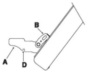
A B DFIG. 6
natural_image
Simple line drawing of a ladder leaning against a vertical post, with motion arrows indicating movement (no text or symbols)FIG. 7
Hob:
- The removable parts of the burners on the hob should be washed frequently with warm water and soap, making sure to remove any caked-on substances. Check that the gas outlet slits are not clogged. Dry the burners carefully before using them again.
- Clean the end part of the automatic glow plug ignitors of the hob and gas oven frequently.
Disassembling/assembling the oven door
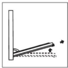
To make it easier to clean the inside of your oven, the oven door can be removed, by proceeding as follows (fig. 6-7):
- Open the door completely and lift the 2 levers "B" (fig. 6);
- Now, shutting the door slightly, you can lift it out by pulling out the hooks "A" as shown in figure 7.
To reassemble the door:
- With the door in a vertical position, insert the two hooks "A" into the slots;
- Ensure that seat "D" is hooked perfectly onto the edge of the slot (move the oven door backwards and forward slightly);
- Keep the oven door open fully, unhook the 2 levers "B" downwards and then shut the door again.
Greasing the taps
As time passes, a tap may lock or become difficult to turn. In this case it will be necessary to clean inside and replace the grease. This procedure must be performed by a technician authorized by the manufacturer.
Changing the oven lightbulb
Make sure that the appliance is disconnected from the electricity supply.
Unscrew the glass protective cover from inside the oven, unscrew the lightbulb and replace it with an identical one suitable for high temperatures (300°C) and with the following characteristics:
- Voltage 230 V
- Wattage 15 W
- Type E 14.
natural_image
Pure technical line drawing of a mechanical assembly without any text, numbers, or symbolsCOOKING TIPS
Cooking times may vary according to the nature of the foods, their homogeneity and their volume. When cooking a certain food for the first time, it is advisable to choose the lowest values in the cooking time range given in the table and then increase them if necessary.
CONVENTIONAL oven cooking
| Type of dish Temperature °C | Cooking time (minutes) | Type of dish Temperature °C Cooking time (hours) | |||
| Pastries and cakes | Meat | ||||
| Fruit pie | 130 | 60-70 | Turkey (4-8 kg) | 160 | 3-412 |
| Meringues | 130 | 30-40 | Goose (4-5 kg) | 160 | 4-412 |
| Sponge cake | 150 | 20-30 | Duck (2-4 kg) | 170 | 112-212 |
| Angel cake | 160 | 40-50 | Capon ( 212-3 kg) | 170 | 2-212 |
| Madeira cake | 160 | 40-50 | Braised beef ( 1-112 kg) | 160 | 3-312 |
| Chocolate cake | 170 | 30-40 | Leg of lamb | 160 | 1-112 |
| Flat sweet loaf | 170 | 40-50 | Roast hare (2 kg) | 160 | 1-112 |
| Puffs | 200 | 15-20 | Roast pheasant | 160 | 1-112 |
| Flaky pastry biscuits | 200 | 15-20 | Chicken ( 1-112 kg) | 170 | 1-112 |
| Mille feuilles | 200 | 15-20 | |||
| Short crust pastry | 200 | 15-20 | Fish | 200 | 15-25 minutes |
GRILLING
| Type of dish | Cooking time (minutes) | Position of shelf |
| Chops (0.5 kg) | 60 | 3^rd guide rail |
| Saussages | 15 | 2^nd guide rail |
| Grilled chicken (1 kg) | 60 | 1^st guide rail |
| Veal on the spit (0.6 kg) | 60 | - |
| Chicken on the spit (1 kg) | 60 | - |
The 1 ^st guide rail is understood as being the lowest position.
FAN ASSISTED cooking
| Type of dish Guide rail no. | from bottom Quantity kg Temperature °C Time (minutes) | |||
| Cakes* With beaten mix, in mould* With beaten mix, without mouldShort pastry, flan baseShort pastry with wet fillingShort pastry with dry filling* With natural leavened mixSmall cakes | 1-31-3-41-3-41-31-3-41-3-4 | 110.51.5110.5 | 175175175175175175160 | 60503070455030 |
| MeatRoasts under the grillVealBeefEnglish roast beefPorkChickenRoasts on a trayVealBeefPorkChickenTurkey slicesDuckCasserolesBeef casseroleVeal casserole | 222222 | 1111-1.5 | 180180220180200 | 6070507070 |
| 1-31-31-31-31-3 | 1111-1.51.51-1.5 | 160160160180180180 | 80909090120120 | |
| 11 | 11 | 175175 | 120110 | |
| FishFillets, steaks, cod, hake, soleMackerel, turbot, salmonOysters | 1-31.31-3 | 11 | 180180180 | 304520 |
| TimbalesBaked pasta dishVegetable pudding* Sweet and savoury soufflés* Pizzas and savoury rollsToasted sandwiches | 1-31-31-31-3-41-3-4 | 220.750.50.5 | 185185180200190 | 6050503015 |
| DefrostingReady-to-eat mealsMeatMeatMeat | 1-31-31-31-3 | 10.50.751 | 200505050 | 455070110 |
Notes:
1) Cooking times do not include oven pre-heating, except for those marked with an asterisk.
2) The indication given in the table for the guide rails is the one that should preferably be used in the event of cooking on more than one level.
3) The indicated times refer to cooking on one shelf only; for cooking on more than one level, increase the time by 5 ÷ 10 minutes.
4) For roast beef, veal, pork and turkey, on the bone or rolled, increase the times by 20 minutes.
The following instructions are provided for qualified installers so that they may accomplish installation, adjustment and technical maintenance operations correctly and in compliance with national current regulations and standards.
Important: the appliance should be disconnected from the mains electricity supply before any adjustment, maintenance, etc. is carried out. Maximum caution should be exercised should it be necessary to keep the appliance connected to the electricity supply.
The cookers have the following technical specifications:
Cat. II2H3+
Class 1
natural_image
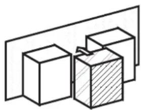
Simple line drawing of three 3D cubes with one shaded and one plain, no text or symbols present.Class 2 sub-class 1
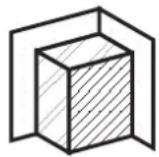
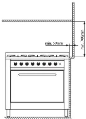
The maximum dimensions of the appliance are given in the figure on page 2. For trouble-free operation of appliances installed in housing units, the minimum distances shown in fig.8 should be observed. Adjacent surfaces and the wall at the rear should also be able to withstand a temperature of 65 °C
fig.9
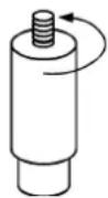
fig.8
Prior to installing the cooker, 99 ÷ 155 mm high supporting feet (provided) should be fitted into the holes to be found in the bottom of the cooker (fig.9). These feet are screw-adjustable and whenever necessary should be used to make sure the cooker stands level.
Positioning (only for UK)
Important: this unit may be installed and used only in permanently ventilated rooms according to the British Standards Codes Of Practice: B.S. 6172/B.S. 5440, Par. 2 and B.S. 6891 Current Editions. The following requirements must be observed:
a) The cooker should not be installed in a bed sitting room with a volume of less than 20m3. If it is installed in a room of volume less than 5m3 an air vent of effective area of 110cm2 is required, if it is installed in a room of
volume between 5m3 and 10m3 a supplementary airvent area of 50cm2 is required, if the volume exceeds 11m3 no airvent is required. However, if the room has a door or a window which opens directly to the outside
no air vent is required even when the volume is between 5m3 and 11m3.
b) During prolonged use of the appliance you may consider it necessary to open a window to the outside to improve ventilation.
c) If there are other fuel burning appliances in the same room, B.S.5440 Part 2 Current Edition, should, be consulted to determine the requisite air vent requirements.
natural_image
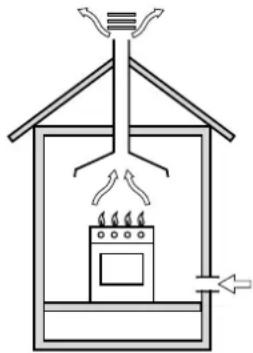
Simple line drawing of a heating or cooling system with a stove and fan (no text or symbols)fig.10
natural_image
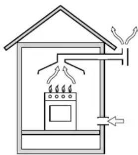
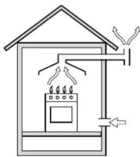
Simple line drawing of a house interior with steam rising from the chimney, showing airflow and ventilation (no text or symbols)In a chimney stack or branched flue Directly to the outside (exclusively for cooking appliances)
Positioning
This appliance may only be installed and operated in permanently ventilated rooms in compliance with provisions laid down by current regulations and standards. The following requirements must be observed:
- The appliance must discharge combustion products into a special hood, which must be connected to a chimney, flue pipe or directly to the outside (fig.10).
- If it is impossible to fit a hood, the use of an electric fan is permitted, either installed on a window or on an external wall, which must be switched on at the same time as the appliance.
Kitchen ventilation
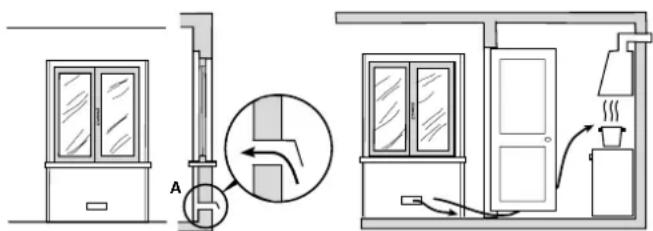
The air flow into the room where the appliance is installed must be equal to the quantity of air that is required for regular combustion of the gas and for ventilating the same room. Air must be taken in naturally through permanent apertures made in the outside walls of the room or through single or branching collective ventilation ducts in compliance with the standards in force. The air must be taken directly from the outside, from an area far from sources of pollution. The ventilation aperture must have the following characteristics (fig.11A):
- total free cross section of passage of at least 6cm^2 for every kW of rated heating capacity of the appliance, with a minimum of 100cm^2 (the heating capacity is indicated on the rating plate);
- it must be made in such a way that the aperture cannot be obstructed both on the inside and outside of the wall;
- it must be protected, e.g. with grills, wire mesh, etc. in such a way that the above-mentioned free section is not reduced;
- it must be situated as near to floor level as possible.
Detail A Adjacent Room to be
room ventilated
text_image
Diagram showing airflow or ventilation system with labeled components and directional arrows, including a valve mechanism and exhaust system.Examples of ventilation holes Enlarging the ventilation slot for comburant air between window and floor
fig. 11A fig.11B
The air inflow may also be obtained from an adjoining room, provided the latter is not a bedroom or a room where there is a risk of fire, such as warehouses, garages, fuel stores, etc. and is ventilated in compliance with the standards in force. Air from the adjoining room to the one to be ventilated may be made to pass freely through permanent apertures with a cross section at least equal to that indicated above. These apertures may also be obtained by increasing the gap between the door and the floor (fig.11B). If an electric fan is used for extracting the combustion products, the ventilation aperture must be increased in relation to its maximum performance. The electric fan should have a sufficient capacity to guarantee an hourly exchange of air equal to 3 ÷ 5 times the volume of the kitchen. Prolonged, intensive use of the appliance may require extra ventilation, e.g. an open window or a more efficient ventilation system by increasing the extraction power of the electric fan if installed. Liquid petroleum gas descends towards the floor as it is heavier than air. Apertures in the outside walls in rooms containing LPG cylinders should therefore be at floor level, in order to allow any gas from leaks to be expelled. Do not store LPG cylinders (even when empty) in basements/rooms below ground level; it is advisable to keep only the cylinder in use in the room and connected far from heat sources which could raise its temperature to above 50°C.
Gas supply
- Check that the appliance is set for the type of gas available and then connect it to the mains gas piping or the gas cylinder in compliance with the applicable norms in force.
- This appliance is designed and set to work with the gas indicated on the label situated on the actual hob. If the gas supply is different from the type for which the appliance has been set, replace the corresponding nozzles (provided), following the instructions given in the paragraph "Adaptation to different types of gas".
- For trouble-free operation, suitable use of energy and a longer life cycle for the appliance, make sure that the supply pressure complies with the values indicated in table 1 "Burner and nozzle specifications", otherwise install a special pressure regulator on the supply pipe in compliance with current standards and regulations.
- Connect in such a way that the appliance is subjected to no strain whatsoever.
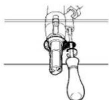
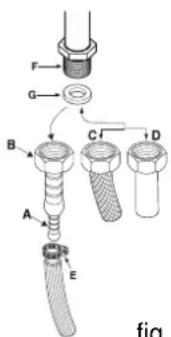
Either a rigid metal pipe with fittings (fig. 12-D) in compliance with norms must be used for connecting to the nipple union (threaded - cylindrical 12 "G fitting "F") situated at the rear of the appliance (fig. 12), or a flexible steel pipe with a continuous wall and fittings (fig. 12-C) in compliance with norms, which must not exceed 2000 mm in length. Check that the connecting pipe cannot come into contact with moving parts which could damage or crush it. For installation with a flexible rubber pipe, apply the special hose support for liquid gas (fig. 12-A) or natural gas (fig. 12-B). The gasket "G" (provided) must be utilised in every type of connection. The two ends of the pipe must be fastened with the purpose designed pipe collars "E", in compliance with the norms. The flexible pipe should comply with the norms, and be specific for the type of gas used. In addition:
- it should be as short as possible, with a maximum length of 1.5 metres;
- it should not be bent or kinked;
- it should not be in contact with the rear panel of the appliance or in any case with parts which may reach a tem-
perature of 50°;
- it should not pass through holes or slits used for discharging the oven flue gases;
- it should not come into contact with pointed parts or sharp corners;
- it should be easy to inspect along its entire length in order to be able to check its condition;
- it should be replaced before the date printed on the actual pipe.
Important: A pressure regulator, in compliance with the applicable norm in force, must be inserted when connecting to a liquid gas supply (in a cylinder).
Upon completion of installation, check for leaks from the gas circuit using a soapy solution (never use a flame). Make sure that the natural gas pipe is adequate for a sufficient supply to the appliance when all the burners are lit.
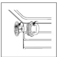
Adapting to different types of gas (instructions for the hob)
To adapt the hob to a different type of gas from the factory-set one (indicated on the rating plate at the top of the hood or on the packaging), the burner nozzles should be replaced as follows:
- Remove the hob grids and slide the burners off their seats.
- Unscrew the nozzles (fig. 13), using a 7 mm socket spanner and replace them with nozzles for the new type of gas (see table 1 "Burner and nozzle characteristics").
Reassemble the parts following the above procedure in the reverse order.
- On completion of this operation, replace the old rating sticker with one indicating the new type of gas used. This sticker is available in the "kit of nozzle".
Replacing the independent "double flame" burner nozzles:
- Remove the grids and slide the burners off their seats. The burner is made up of three separate parts (see Fig. C and Fig. D);
- Unscrew the nozzles using a 7 mm socket spanner. The inner burner has one nozzle, while the outer one has two (of the same size). Replace the nozzles with those for the new type of gas (see table 1).
- Replace all the parts, following the steps described above in the reverse order.
Fig. C
Fig. D
text_image
F G B C D A E fig.fig.12
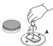
fig.13
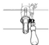
fig.14
Adjusting the primary air of the burners
The primary air of the burners does not need to be adjusted.
Adjusting the low flame
- Turn the tap to the low flame position;
- Remove the knob and turn the adjusting screw, situated to the right of the tap (fig. 14) until you obtain a regular small flame, using a screwdriver (loosening the screw increases the height of the flame, tightening decreases it).
N.B.: In the case of liquid gas, the regulation screw must be screwed in all the way.
- Having obtained the low flame setting required and with the burner lit, abruptly change the position of the knob several times from minimum to maximum and vice versa and check that the flame does not go out.
- In appliances fitted with the safety device (thermocouple), should the device fail to work with the burners set to the low flame setting, increase the low flame setting of the same on the adjusting screw.
Once the adjustment has been made, remount the seals on the by-passes using sealing wax or similar.
Gas oven (CP 057 GT - CP 058 GT (X) F - CP 857 GT):
- Open the oven door (to reach the oven burner, remove the floor);
- loosen the 2 screws which hold the oven burner in place, remove the burner and replace the nozzles "N" with suitable ones for the new type of gas according to the table on page 12.
- re-assemble all the components, regulate the air in the burner as well as the minimum flow of the tap.
Adjusting the low flame
- Open the door and remove the oven floor;
- put the oven knob to position maximum and light the burner;
- close the door and wait for about 15 minutes;
- put the knob to position 1 (minimum);
- remove the actual knob and regulate the adjusting screw situated above the thermostat spindle;
• after regulating the low flame as required, with the burner lit, change from the high to the low flame position abruptly for a few times and close the oven door normally, making sure that the burner does not go out.
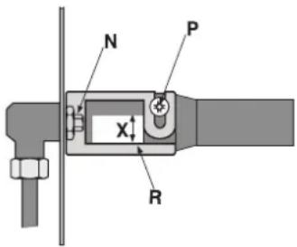
Primary air flow control
The oven burners and grill are fitted with the primary air control bushing "R" (fig. 15: gas oven burners). The primary air flow is controlled in an appropriate way when the flame is stable and even, without killing the flame when the burner is cold or lighting the nozzle when the burner is hot. The flow may be adjusted by loosening the screw "P" and moving the bushing "R" so that the opening "X" corresponds to the values in the table below. Once all the adjustments have been made, fasten the bushing "R" with the screw "P".
fig.15
text_image
N P X R| Burner | Opening "X" (mm)natural gas"G20" | Opening "X" (mm)liquid gas"G30-G31" |
| Oven 6.5 10 | ||
| Grill 5 12 |
Electrical connection
THE APPLIANCE MUST BE EARTHED
The appliance is designed to work with alternating current at the supply voltage and frequency indicated on the rating plate (situated on the rear part of the appliance and on the last page of the instruction manual). Make sure that the local supply voltage corresponds to the voltage indicated on the rating plate.
Connecting the supply cable to the mains electricity supply
For models supplied without a plug, fit a standard plug, suitable for the load indicated on the rating plate, onto the cable and connect it to a suitable socket.
To connect directly to the mains supply, an omnipolar circuit-breaker with a contact separation of at least 3 mm suitable for the load and complying with current standards and regulations must be fitted between the appliance and the mains supply outlet.
The yellow-green earth wire must not be interrupted by the switch.
The supply cable must be in such a position so that no part of it can reach a temperature of 50 °C above room temperature.
All appliances should be connected separately.
Do not use reducers, adapters or shunts as they could cause heating or burning.
Before connecting to the power supply, make sure that:
- the limiter valve and the domestic system can withstand the load from the appliance (see rating plate);
- the supply system is efficiently earthed according to standards and laws in force;
- the socket or omnipolar circuit-breaker are easily accessible when the appliance is installed.
FAILURE TO OBSERVE THE ACCIDENT-PREVENTION REGULATIONS RELIEVES THE MANUFACTURER OF ALL LIABILITY.
Replacing the cable
Use a rubber cable of the type H05VV-F with a cross section of 3 × 1.5 mm^2 .
The yellow-green earth wire must be 2 ÷ 3 cm longer than the other wires.
TROUBLESHOOTING
It may occur that the appliance does not function or does not function properly. Before calling customer services for assistance, let's see what can be done.
First of all, check to see that there are no interruptions in the gas and electrical supplies, and, in particular, that the gas valves for the mains are open.
The burner does not light or the flame is not uniform around the burner.
Check to make sure that:
- The gas holes on the burner are not clogged;
- All the removable parts that make up the burner are mounted correctly;
- There are no draughts around the cooking surface.
The flame does not stay on
Check to make sure that:
- You press the knob all the way in;
- You keep the knob pressed in long enough to activate the safety device.
- The gas holes are not clogged in the area corresponding to the safety device.
The burner does not remain on when set to "Low".
Check to make sure that:
• The gas holes are not clogged.
- There are no draughts near the cooking surface.
- The minimum has been adjusted correctly (see the section entitled, "Adjusting the low flame").
The cookware is not stable.
Check to make sure that:
- The bottom of the cookware is perfectly flat.
- The cookware is centered correctly on the burner.
If, despite all these checks, the appliance does not function properly and the problem persists, call the nearest Indesit Company Customer Service Centre, informing them of: - The type of problem.
- The abbreviation used to identify the model (Mod. ...) as indicated on the warranty.
Never call on technicians not authorised by the manufacturer, and always refuse to accept spare parts that are not original.
BURNER AND NOZZLE SPECIFICATIONS
| Table 1 Liquid gas Natural gas | |||||||||
| BURNER | Diameter (mm) | Thermal power kW (H.s.*) | By-pass 1/100 (mm) | Injector 1/100 (mm) | Flow * g/h | Injector 1/100 (mm) | Flow* I/h G20 | ||
| Nomin. | Reduc. | G30 | G31 | ||||||
| C.Rapid | 100 | 3.00 | 0.7 | 40 | 86 | 218 | 214 | 116 | 286 |
| B. Semi-rapid | 75 | 1.65 | 0.4 | 30 | 64 | 120 | 118 | 96 | 157 |
| A. Auxiliary | 55 | 1.00 | 0.3 | 27 | 50 | 73 | 71 | 71 | 95 |
| D. Triple Ring | 130 | 3.25 | 1.3 | 57 | 91 | 236 | 232 | 124 | 309 |
| I. Double flame DC DR (internal) | 30 | 0.90 | 0.4 | 30 | 44 | 65 | 64 | 72 | 86 |
| I. Double Flame DC DR (external) | 130 | 4.10 | 1.3 | 57 | 70 | 298 | 293 | 110 | 390 |
| Gas Oven | 4.00 | 0.8 | 45 | 95 | 291 | 286 | 142 | 381 | |
| Supply pressure | Nominal Minimum Maximum | 28-30 20 35 | 37 25 45 | 20 17 25 | |||||
* At 15°C and 1013 mbar-dry gas
Propane G31 H.s. = 50,37 MJ/kg
Butane G30 H.s. = 49,47 MJ/kg
Methane G20 H.s. = 37,78 MJ/m

This appliance conforms to the following European Economic Community directives:
- 73/23/EEC of 19/02/73 (Low Voltage) and subsequent modifications;
- 89/336/EEC of 03/05/89 (Electromagnetic Compatibility) and subsequent modifications;
- 90/336/EEC of 29/06/90 (Gas) and subsequent modifications;
- 93/68/EEC of 22/07/93 and subsequent modifications.
OVEN TECHNICAL SPECIFICATIONS
ENERGY LABEL
Directive 2002/40/EC on the label of electric ovens
Norm EN 50304
Energy consumption for Natural convection:
heating mode: Convection
Declared energy consumption for Forced convection Class:
heating mode: ☑an assisted
flowchart
graph TD
    M --> A["Circle with curved arrow"]
    M --> B["Circle with curved arrow"]
    M --> C["Circle with curved arrow"]
    M --> D["Circle with curved arrow"]
    M --> E["Circle with curved arrow"]
    M --> F["Circle with curved arrow"]
    M --> V["Circle with curved arrow"]
    V --> W["Circle with dashed line"]
    S --> X["Circle with dot"]
    Z --> Y["Circle with dot"]
    T --> Z
    style M fill:#f9f,stroke:#333
    style V fill:#ccf,stroke:#333
    style S fill:#cfc,stroke:#333
    style Z fill:#fcc,stroke:#333
    style T fill:#cff,stroke:#333
CP 058 GT (X) F
flowchart
graph TD
    A["M"] --> B["Process Node"]
    C["M"] --> D["Process Node"]
    E["M"] --> F["Process Node"]
    G["M"] --> H["Process Node"]
    I["P"] --> J["Process Node"]
    K["H"] --> L["Process Node"]
    M["G"] --> N["Process Node"]
    O["ARSTON"] --> P["Process Node"]
    Q["Square"] --> R["Process Node"]
    S["Square"] --> T["Process Node"]
    U["Square"] --> V["Process Node"]
    W["Square"] --> X["Process Node"]
CP 059 MD.3 (X) F
text_image
D/I R 800 - 900 A C B 600 B 750 95÷155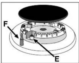
text_image
F Efig.1
natural_image
Three identical line-drawn icons of a pot with crossed x marks, placed on a surface (no text or symbols)FOUR GAZ-GRIL ELECTRIQUE
natural_image
Line drawing of a hand using a tool to clean or install a window on a surface (no text or symbols)natural_image
Technical line drawing of a kitchen appliance with grilles and control knobs (no text or symbols)fig.4
natural_image
Simple line drawing of a ladder leaning against a wall, with motion arrows indicating movement (no text or symbols)FIG. 7
natural_image
Pure mechanical diagram showing a valve or fitting assembly without any text, numbers, or symbolsCONSEILS POUR LA CUISSON
natural_image
Simple line drawing of three 3D cubes with one shaded and one unshaded, connected by a plane (no text or symbols)text_image
Diagram showing airflow or ventilation system with labeled components and directional arrows, including a valve mechanism and exhaust system.| Bruleur | Overture "X" (mm) gaz Naturels "G20" | Overture "X" (mm) gaz liquides"G30-G31" |
| Four 6.5 10 | ||
| Grill 5 12 |
natural_image
Three identical line-drawn icons of a cooking pot with crossed x-leafed pans, placed on a flat surface (no text or symbols)natural_image
Line drawing of a kitchen sink with a hand holding a tool, no text or symbols presentnatural_image
Technical line drawing of an oven with a rack and control panel (no text or symbols)fig.4
natural_image
Simple line drawing of a ladder leaning against a wall, with no text or symbols present.FIG.7
natural_image
Pure technical line drawing of a pipe fitting with no text or symbolsnatural_image
Simple line drawing of three 3D cubes with one shaded and one unshaded, connected by a plane (no text or symbols)natural_image
Simple line drawing of a house interior with a stove, roof, and air vent (no text or symbols)fig.10
natural_image
Simple line drawing of a house interior with a stove, air ducts, and cooling system (no text or symbols)text_image
Diagram showing airflow and ventilation system in a room with labeled components and directional arrowstext_image
M M M M M U H G ARISTONCP 058 MT.2
flowchart
graph TD
    M1["M"] --> A["○"]
    M2["M"] --> B["○"]
    M3["M"] --> C["○"]
    M4["M"] --> D["○"]
    P["P"] --> E["□"]
    H["H"] --> F["●"]
    G["G"] --> F
    A --> G
    B --> F
    C --> F
    D --> F
    E --> F
    F --> G
    style A fill:#fff,stroke:#000
    style B fill:#fff,stroke:#000
    style C fill:#fff,stroke:#000
    style D fill:#fff,stroke:#000
    style E fill:#fff,stroke:#000
    style F fill:#fff,stroke:#000
    style G fill:#fff,stroke:#000
CP 059 MT.2 - CP 859 MT.2
flowchart
graph TD
    M --> A["○"]
    M --> B["○"]
    M --> C["○"]
    M --> D["○"]
    M --> E["○"]
    M --> F["○"]
    V --> S["○"]
    V --> T["○"]
    S --> U["○"]
    T --> V
    style M fill:#f9f,stroke:#333
    style V fill:#f9f,stroke:#333
    style S fill:#ccf,stroke:#333
    style T fill:#ccf,stroke:#333
CP 057 GT - CP 857 GT
flowchart
graph TD
    M1["M"] --> A["Circle"]
    M2["M"] --> B["Circle"]
    M3["M"] --> C["Circle"]
    M4["M"] --> D["Circle"]
    M5["M"] --> E["Circle"]
    P["P"] --> F["Box with dots"]
    H["H"] --> G["Circle with dots"]
    G["G"] --> H
    A --> I["Square"]
    B --> J["Square"]
    C --> K["Square"]
    D --> L["Square"]
    E --> M["Square"]
    F --> N["Square"]
    G --> O["Square"]
CP 059 MD.2
text_image
D/I R 800 - 900 A C B 600 B 750 95÷155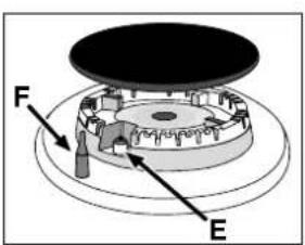
text_image
F Efig.1
INSTRUÇÕES PARA O USO
Queimadores a gás
natural_image
Three identical line drawings of cooking pots with crossed x marks, no text or symbols presentFORNO GÁS-GRILL ELÉCTRICO
natural_image
Line drawing of a hand using a tool to clean or store items inside a kitchen appliance (no text or symbols visible)natural_image
Technical line drawing of a cabinet interior with control knobs and a door handle (no text or symbols)fig.4
natural_image
Simple line drawing of a ladder leaning against a vertical post, with arrows indicating motion (no text or symbols)FIG. 7FIG.6
Desmontar/montar a porta do forno
natural_image
Pure technical line drawing of a mechanical assembly with no text or symbolsCONSELHOS PARA A COZEDURA
natural_image
Simple line drawing of three 3D cubes with one shaded and one plain, no text or symbols present.Classe 2 subclasse 1