
AKS 1400 - Oven IGNIS - Free user manual and instructions
Find the device manual for free AKS 1400 IGNIS in PDF.



| Product type | Built-in oven |
| Brand | Ignis |
| Model | AKS 1400 |
| Category | Oven |
| Dimensions (W x H x D) | 595 x 595 x 565 mm (standard) |
| Weight | Approximately 30 kg |
| Power supply | 230 V, 50 Hz, cable H05 RR-F 3x1.5 mm² |
| Total power | Approximately 3.0 kW |
| Main functions | Natural convection, Grill, Bottom heat, Light, Rotisserie (depending on model) |
| Cleaning | Manual (no pyrolysis on this standard model) |
| Accessories supplied | Grid, drip tray, baking tray, side catalytic panels, grease filter, sliding grids, rotisserie (depending on model) |
| Interior lighting | Incandescent bulb 25-40W/230V, type E-14, T300°C |
| Number of shelf levels | 5 (numbered from bottom to top) |
| Maximum temperature | 250°C |
| Safety | Control lock, automatic shutdown not specified, door with safety hinges |
| Spare parts available | E-14 bulb, heating elements, catalytic panels, grease filter, grids, rotisserie |
| Repairability | Door and upper heating element disassembly possible by user; other interventions by authorized after-sales service |
| Warranty | Legal warranty (refer to warranty booklet) |
| Repairability index | Not communicated |
| General information | Compliant with Low Voltage Directive 2006/95/EC and EMC Directive 2004/108/EC |
Frequently Asked Questions - AKS 1400 IGNIS
User questions about AKS 1400 IGNIS
0 question about this device. Answer the ones you know or ask your own.
Ask a new question about this device
Download the instructions for your Oven in PDF format for free! Find your manual AKS 1400 - IGNIS and take your electronic device back in hand. On this page are published all the documents necessary for the use of your device. AKS 1400 by IGNIS.
USER MANUAL AKS 1400 IGNIS
(Apply the label from warranty here)
SERVICE
GB User and maintenance manual
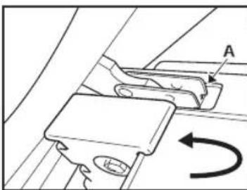
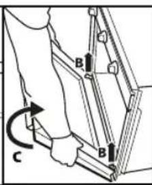
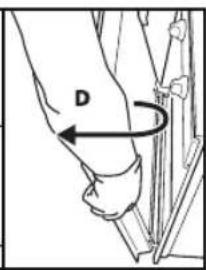
Fig. 1 Fig. 2
LOWERING THE UPPER GRILL ELEMENT (ONLY ON SOME MODELS)
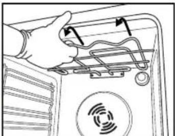
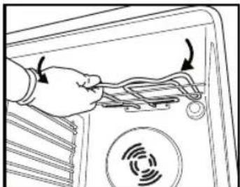
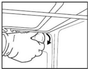
Fig. 6 Fig. 7
NOTE:
Fig. 9
Drip tray (Fig. 1)
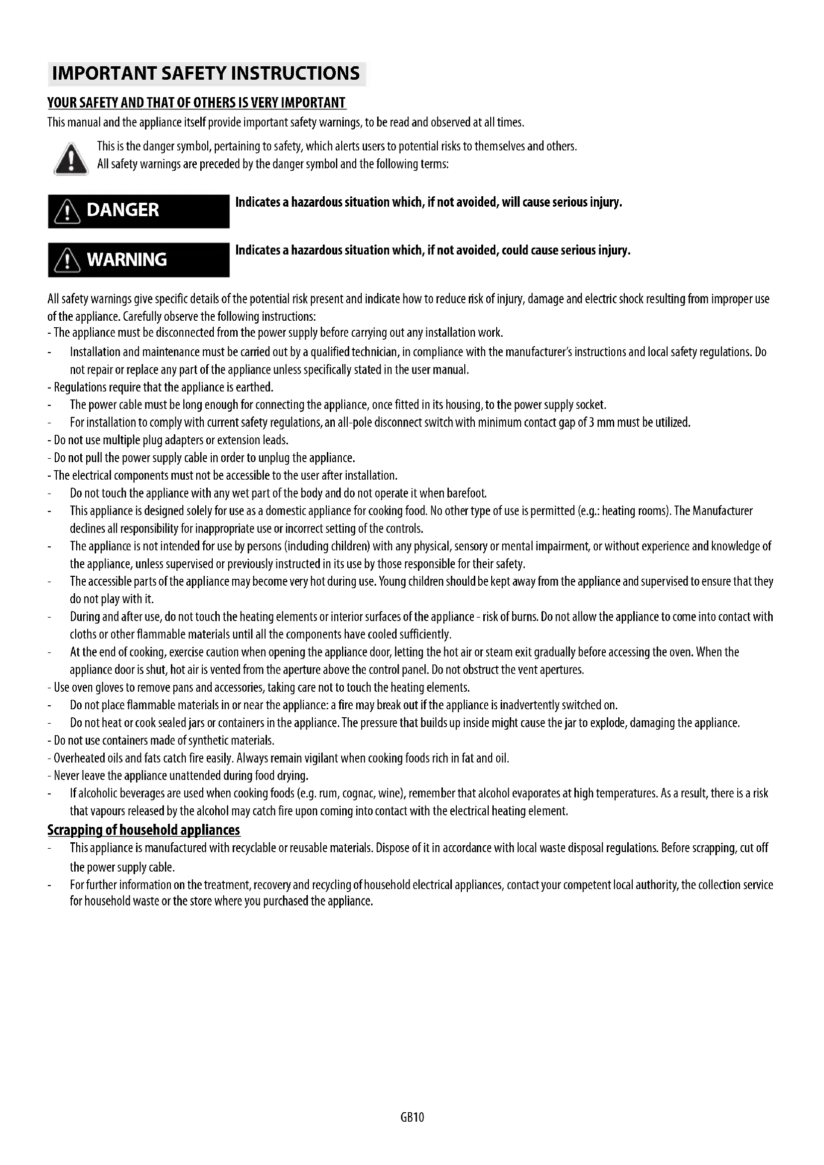
IMPORTANT SAFETY INSTRUCTIONS
YOUR SAFETY AND THAT OF OTHERS IS VERY IMPORTANT
This manual and the appliance itself provide important safety warnings, to be read and observed at all times.

This is the danger symbol, pertaining to safety, which alerts users to potential risks to themselves and others.
All safety warnings are preceded by the danger symbol and the following terms:

DANGER

WARNING
Indicates a hazardous situation which, if not avoided, will cause serious injury.
Indicates a hazardous situation which, if not avoided, could cause serious injury.
All safety warnings give specific details of the potential risk present and indicate how to reduce risk of injury, damage and electric shock resulting from improper use of the appliance. Carefully observe the following instructions:
- The appliance must be disconnected from the power supply before carrying out any installation work.
- Installation and maintenance must be carried out by a qualified technician, in compliance with the manufacturer's instructions and local safety regulations. Do not repair or replace any part of the appliance unless specifically stated in the user manual.
- Regulations require that the appliance is earthed.
- The power cable must be long enough for connecting the appliance, once fitted in its housing, to the power supply socket.
- For installation to comply with current safety regulations, an all-pole disconnect switch with minimum contact gap of 3 mm must be utilized.
- Do not use multiple plug adapters or extension leads.
- Do not pull the power supply cable in order to unplug the appliance.
- The electrical components must not be accessible to the user after installation.
- Do not touch the appliance with any wet part of the body and do not operate it when barefoot.
- This appliance is designed solely for use as a domestic appliance for cooking food. No other type of use is permitted (e.g.: heating rooms). The Manufacturer declines all responsibility for inappropriate use or incorrect setting of the controls.
- The appliance is not intended for use by persons (including children) with any physical, sensory or mental impairment, or without experience and knowledge of the appliance, unless supervised or previously instructed in its use by those responsible for their safety.
- The accessible parts of the appliance may become very hot during use. Young children should be kept away from the appliance and supervised to ensure that they do not play with it.
- During and after use, do not touch the heating elements or interior surfaces of the appliance - risk of burns. Do not allow the appliance to come into contact with cloths or other flammable materials until all the components have cooled sufficiently.
- At the end of cooking, exercise caution when opening the appliance door, letting the hot air or steam exit gradually before accessing the oven. When the appliance door is shut, hot air is vented from the aperture above the control panel. Do not obstruct the vent apertures.
- Use oven gloves to remove pans and accessories, taking care not to touch the heating elements.
- Do not place flammable materials in or near the appliance: a fire may break out if the appliance is inadvertently switched on.
- Do not heat or cook sealed jars or containers in the appliance. The pressure that builds up inside might cause the jar to explode, damaging the appliance.
- Do not use containers made of synthetic materials.
- Overheated oils and fats catch fire easily. Always remain vigilant when cooking foods rich in fat and oil.
- Never leave the appliance unattended during food drying.
- If alcoholic beverages are used when cooking foods (e.g. rum, cognac, wine), remember that alcohol evaporates at high temperatures. As a result, there is a risk that vapours released by the alcohol may catch fire upon coming into contact with the electrical heating element.
Scrapping of household appliances
- This appliance is manufactured with recyclable or reusable materials. Dispose of it in accordance with local waste disposal regulations. Before scrapping, cut off the power supply cable.
- For further information on the treatment, recovery and recycling of household electrical appliances, contact your competent local authority, the collection service for household waste or the store where you purchased the appliance.
INSTALLATION
After unpacking the oven, be sure that it has not been damaged during transport and that the oven door closes properly. In the event of problems, contact the dealer or your nearest After-sales Service. To avoid any damage, only remove the oven from its polystyrene foam base at the time of installation.
PREPARING THE HOUSING UNIT
- Kitchen units in contact with the oven must be heat resistant (min 90°C).
- Carry out all cabinet cutting work before fitting the oven in the housing and carefully remove all wood chips and sawdust.
- After installation, the bottom of the oven must no longer be accessible.
- For correct appliance operation, do not obstruct the minimum gap between the worktop and the upper edge of the oven.
ELECTRICAL CONNECTION
Be sure the power voltage specified on the appliance dataplate is the same as the mains voltage. The dataplate is on the front edge of the oven (visible when the door is open).
- Power cable replacement (type H05 RR-F 3 x 1.5 mm 2 ) must be carried out by a qualified electrician. Contact an authorized service centre.
GENERAL RECOMMENDATIONS
Before use:
- Remove cardboard protection pieces, protective film and adhesive labels from accessories.
- Remove the accessories from the oven and heat it at 200° for about an hour to eliminate the smell and fumes from the insulating materials and protective grease.
During use:
- Do not place heavy objects on the door as they could damage it.
- Do not cling to the door or hang anything from the handle.
- Do not cover the inside of the oven with aluminium foil.
- Do not pour water into the inside of a hot oven; this could damage the enamel coating.
- Do not drag pots or pans across the bottom of the oven as this could damage the enamel coating.
- Be sure that the electrical cables of other appliances do not touch hot parts of the oven or become trapped in the door.
- Do not expose the oven to atmospheric agents.
SAFEGUARDING THE ENVIRONMENT

Disposal of packing material
The packing material is 100% recyclable and is marked with the recycle symbol (☐). The various parts of the packing must therefore be disposed of responsibly and in full compliance with local authority regulations governing waste disposal.
Scrapping the product
- This appliance is marked in compliance with European Directive 2002/96/EC, Waste Electrical and Electronic Equipment (WEEE).
- By ensuring this product is disposed of correctly, you will help avoid potential negative consequences for the environment and human health, which could otherwise be caused by inappropriate waste handling of this product.
- The symbol ☒ on the product or on the accompanying documentation indicates that it should not be treated as domestic waste but must be taken to an appropriate collection centre for the recycling of electrical and electronic equipment.
Energy saving
- Only pre-heat the oven if specified in the cooking table or your recipe.
- Use dark lacquered or enamelled baking moulds as they absorb heat far better.
- Switch the oven off 10/15 minutes before the set cooking time. Food requiring prolonged cooking will continue to cook even once the oven is switched off.
DECLARATION OF CONFORMITY C€
This oven, which is intended to come into contact with foodstuffs, complies with European Regulation (C €) n.1935/2004 and has been designed, manufactured and sold in conformity with the safety requirements of the "Low Voltage" directive 2006/95/CE (which replaces 73/23/CEE and subsequent amendments), the protection requirements of "EMC" 2004/108/CE.
TROUBLESHOOTING GUIDE
The oven does not work:
- Check for the presence of mains electrical power and if the oven is connected to the electrical supply.
- Turn off the oven and restart it to see if the fault persists.
The door will not open:
- Turn off the oven and restart it to see if the fault persists.
- Important: during self-cleaning, the oven door will not open. Wait until it unlocks automatically (see paragraph "Cleaning cycle of ovens with pyrolysis function").
The electronic programmer does not work:
- If the display shows the letter "F" followed by a number, contact your nearest After-sales Service. Specify in this case the number that follows the letter "F".
AFTER-SALES SERVICE
Before calling the After-Sales Service:
- See if you can solve the problem yourself with the help of the suggestions given in the "Troubleshooting guide".
- Switch the appliance off and back on again to see if the fault persists.
If after the above checks the fault still occurs, get in touch with the nearest After-sales Service.
Always specify:
- a brief description of the fault; • the type and exact model of the oven;
- the service number (number after the word Service on the rating plate), located on the right hand edge of the oven cavity (visible when the oven door is open). The service number is also indicated on the guarantee booklet;
- your full address;
- your telephone number.
SERVICE
If any repairs are required, please contact an authorised After-sales Service (to guarantee that original spare parts will be used and repairs carried out correctly).
CLEANING

WARNING
- Do not use steam cleaning equipment.
- Clean the oven only when it is cool.
- Disconnect power before servicing.
Oven exterior
IMPORTANT: do not use corrosive or abrasive detergents. If any of these products unintentionally comes into contact with the appliance, clean immediately with a damp cloth.
• Clean the surfaces with a damp cloth. If it is very dirty, add a few drops of washing up detergent to the water. Finish off with a dry cloth.
Oven interior
IMPORTANT: do not use abrasive sponges or metallic scrapers or scourers. Over time, these can ruin enamelled surfaces and the oven door glass.
- After every use, allow the oven to cool then clean it preferably while it is still warm in order to remove built-up dirt and stains caused by food residues (e.g. food with a high sugar content).
- Use proprietary oven detergents and follow the manufacturer's instructions to the letter.
- Clean the door glass with a suitable liquid detergent. The oven door can be removed to facilitate cleaning (see MAINTENANCE). • The top heating element of the grill (see MAINTENANCE) can be lowered (some models only) to clean the roof of the oven.
N.B: during prolonged cooking of foods with a high water content (e.g. pizza, vegetables, etc.) condensation may form on the inside of the door and around the seal. When the oven is cold, dry the inside of the door with a cloth or sponge.
Accessories:
• Soak the accessories in water with washing up detergent immediately after use, handling them with oven gloves if still hot. - Food residues can be easily removed using a brush or sponge.
Cleaning the rear wall and catalytic side panels of the oven (if present):
IMPORTANT: do not use corrosive or abrasive detergents, coarse brushes, pot scourers or oven sprays which could damage the catalytic surface and ruin its self-cleaning properties.
- Operate the oven empty with the fan-assisted function at 200°C for about one hour
- Next, leave the appliance to cool down before removing any food residue with a sponge.
MAINTENANCE

WARNING
- Use protective gloves.
- Ensure the oven is cold before carrying out the following operations.
- Disconnect power before servicing.
REMOVING THE DOOR
To remove the door:
- Open the door fully.
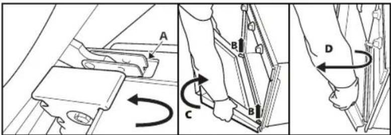
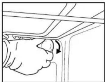
- Lift the catches and push them forwards as far as they will go (fig. 1).
- Close the door as far as it will go (A), lift it up (B) and turn it (C) until it is released (D) (fig. 2).
To refit the door:
- Insert the hinges in their seats.
- Open the door fully.
- Lower the two catches.
- Close the door.
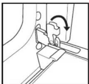
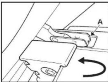
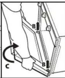
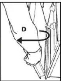
Fig. 1 Fig. 2
MOVING THE TOP HEATING ELEMENT (SOME MODELS ONLY)
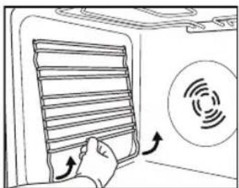
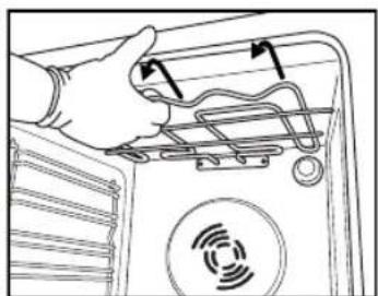
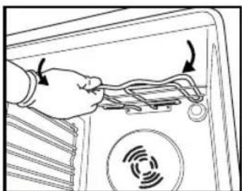
- Remove the side accessory holder grilles (Fig. 3).
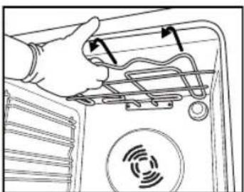
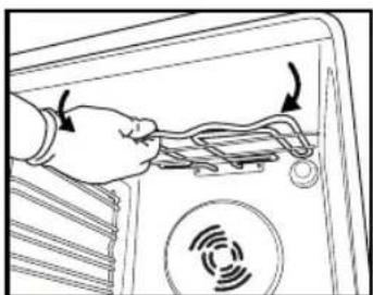
- Pull the heating element out a little (Fig. 4) and lower it (Fig. 5).
- To reposition the heating element, lift it up, pulling it slightly towards you, and be sure it comes to rest on the lateral supports.
- Disconnect the oven from the power supply.
- Unscrew the lamp cover (Fig. 6), replace the lamp (see note for lamp type), and screw the lamp cover back on (Fig. 7).
- Reconnect the oven to the power supply.
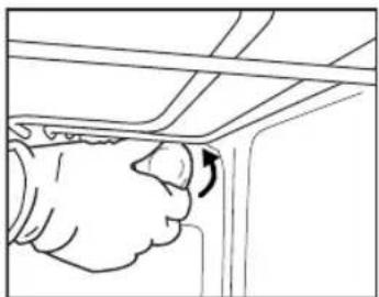
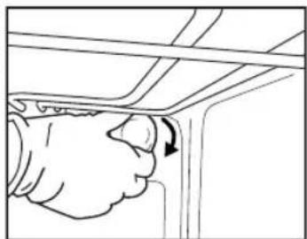
Fig. 6 Fig. 7
N.B.:
- Only use 25-40W/230V type E-14, T300°C incandescent lamps.
- Lamps are available from our After-sales Service.
IMPORTANT:
- Do not use the oven until the lamp cover has been repositioned.
INSTRUCTIONS FOR OVEN USE
FOR ELECTRICAL CONNECTION, SEE THE PARAGRAPH ON INSTALLATION

- Control panel
- Upper heating element/grill
- Cooling system (if present)
- Dataplate (not to be removed)
- Light
- Baking ventilation system (if present)
- Turnspit (if present)
- Lower heating element (not visible)
- Door
- Position of shelves
- Rear wall
N.B.:
- At the end of cooking, after the oven has been switched off, the cooling fan may continue to run for a while.
COMPATIBLE ACCESSORIES
(for the accessories supplied with oven refer to the tech fiche)
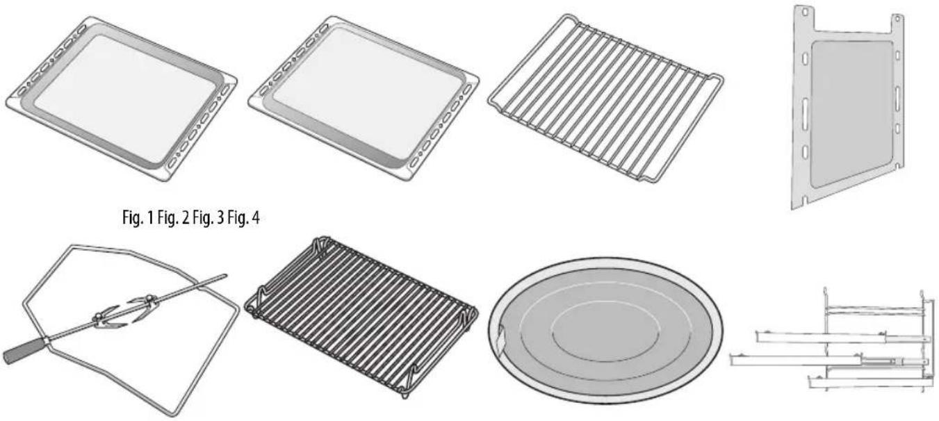
Fig. 9
Drip-tray (Fig. 1)
For collecting fat and bits of food when placed under the wire shelf, or as a plate for cooking meat, chicken and fish, etc., with or without vegetables. Pour a little water into the drip-tray to avoid spatters of fat and smoke.
Baking tray (Fig. 2)
For baking biscuits, cakes and pizzas.
Wire shelf (Fig. 3)
For grilling food or as a support for pots, cake tins and other cooking receptacle. It can be placed on any available level. The wire shelf can be inserted with its curvature facing up or down.
Catalytic side panels (Fig. 4)
These panels have a special microporous enamel coating that absorbs fat spatters. It is advisable to do an automatic cleaning cycle after cooking particularly fatty food (see CLEANING).
Turnspit (Fig. 5)
Use the turnspit as indicated on Fig. 9. Also check "Recommended use and tips" section for advice.
Grill Pan Set (Fig. 6)
This grid is to be used in combination with Drip-tray (1) obtaining Grill Pan Set.
Grease filter (Fig. 7)
Use only for particularly greasy cooking. Hook it on the rear wall of the oven compartment, opposite the fan. It can be cleaned in a dishwasher and used with the fan-assisted function.
Sliding shelves (Fig. 8)
They allow the wire shelves and drip-trays to be pulled half out during cooking. Suitable for all the accessories, they can be cleaned in a dishwasher.
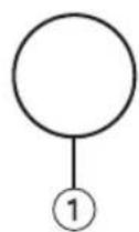
![graph TD A["Circle"] --> B["②"] C["Circle"] --> D["③"]](/content/2026/02/399855/images/635d47991d0c0090e9456725b4e74c530c9a6bd486c26c6e6e24d6c6323d7f69.jpg)
- Function selector knob
- Thermostat knob
- Red thermostat led.
Turn the selector knob to the required function.
The oven light switches on. Turn the thermostat knob clockwise to the required temperature.
The red thermostat led lights up, switching off again when the oven reaches the selected temperature.
At the end of cooking, turn the knobs to "0".
FUNCTION DESCRIPTION TABLE
| FUNCTION DESCRIPTION | ||
 | OFF - | |
| LAMP To switch on the oven light. | ||
 | BOTTOM | This function can be used to finish cooking filled pies or to thicken soups. Use this function for the last 10/15 minutes of cooking. |
 | CONVENTIONAL | Function suitable for cooking any type of dish on one shelf. Preheat the oven to the required temperature and place the food in it when the set temperature is reached. It is advisable to use the second or third shelf for cooking. This function is also suitable for cooking frozen convenience foods; follow the instructions on the food packaging. |
 | GRILL | To grill steak, kebabs and sausages, to cook vegetables au gratin and to toast bread. Preheat the oven for 3-5 min. During cooking the oven door must remain closed. When cooking meat, pour a little water into the drip tray (on the first shelf) to reduce smoke and fat spatters. Ideally the meat should be turned during cooking. |
COOKING TABLE
| Recipe Function Preheating Shelf | (from bottom) | Temperature (°C) | Time (min) | Accessories | ||
| Leavened cakes |  | - | 2 | 160-180 | 35-55 | Wire shelf + cake tin |
| Biscuits/Tartlets |  | - | 3 | 170-180 | 15-40 | Baking tray |
| Choux buns |  | - | 3 | 180 | 30-40 | Baking tray |
| Vols-au-vent / Puff pastry crackers |  | - 3 180-200 | 20-30 Baking tray | |||
| Meringues |  | - | 3 | 90 | 120-130 | Baking tray |
| Lamb / Veal / Beef / Pork |  | - | 2 | 190-200 | 90-110 | Drip tray or wire shelf + pyrex dish |
| Chicken / Rabbit / Duck |  | - | 2 | 190-200 | 65-85 | Drip tray or wire shelf + pyrex dish |
| Turkey / Goose |  | - | 2 | 190-200 | 140-180 | Drip tray or wire shelf + pyrex dish |
| Baked fish / en papillote (fillet, whole) |  | - | 2 | 180-200 | 50-60 | Drip tray or wire shelf + pyrex dish |
| Lasagne / Baked pasta / Cannelloni / Flans |  | - | 2 | 190-200 45-55 | Wire shelf + pyrex dish | |
| Bread / Focaccia |  | - | 2 | 190-230 | 15-50 | Drip tray or baking tray |
| Pizza |  | - | 2 | 230-250 | 7-20 | Drip tray or baking tray |
| Toast |  | - | 4 | 200 | 2-5 | Wire shelf |
| Vegetable gratin |  | - | 3 | 200 | 15-20 | Wire shelf + pyrex dish |
| Grilled fish fillets and steaks |  | - 3 200 30-40 | Wire shelf + pyrex dish | |||
| Sausages / Kebabs / Spare ribs / Hamburgers |  | - 4 200 30-50 | Grill + drip tray with water on 1st shelf, turn halfway through cooking |
N.B: Cooking times and temperatures are approximate for 4 portions.
How to read the cooking table
The table indicates the best function to use for any given food, to be cooked on one or more shelves at the same time. Cooking times start from the moment food is placed in the oven, excluding pre-heating (where required). Cooking temperatures and times are purely for guidance and will depend on the amount of food and type of accessory used. Use the lowest recommended values to begin with and, if the food is not cooked enough, then move on to higher values. Use the accessories supplied and preferably dark coloured metal cake tins and oven trays. You can also use pans and accessories in pyrex or stoneware, but bear in mind that cooking times will be slightly longer. To obtain best results, follow the advice given in the cooking table for the choice of accessories (supplied) to be placed on the various shelves. When cooking food that contains lots of water, preheat the oven.
Cooking different foods at the same time
Using the “CONVECTION BAKE” function (if present), you can cook different foods which require the same cooking temperature at the same time (for example: fish and vegetables), using different shelves. Remove the food which requires less cooking time and leave food which requires longer cooking time in the oven.
Desserts
- Cook delicate desserts with the conventional function on one shelf only. Use dark coloured metal cake tins and always position them on the wire shelf supplied. To cook on more than one shelf, select the forced air function and stagger the position of the cake tins on the shelves, aiding optimum circulation of the hot air.
- To check whether a raising cake is cooked, insert a wooden toothpick into the centre of the cake. If the toothpick comes out clean, the cake is ready.
- If using non-stick cake tins, do not butter the edges as the cake may not rise evenly around the edges.
- If the cake "sinks" during cooking, set a lower temperature the next time, perhaps reducing the amount of liquid in the mixture and mixing more gently.
- For sweets with moist fillings (cheesecake or fruit pies) use the "CONVECTION BAKE" function (if present). If the base of the cake is soggy, lower the shelf and sprinkle the bottom of the cake with breadcrumbs or biscuit crumbs before adding the filling.
Meat
- Use any kind of oven tray or pyrex dish suited to the size of the piece of meat being cooked. For roast joints, it is best to add some stock to the bottom of the pan, basting the meat during cooking for added flavour. When the roast is ready, let it rest in the oven for another 10-15 minutes, or wrap it in aluminium foil.
- When you want to grill meat, choose cuts with an even thickness all over in order to achieve uniform cooking results. Very thick pieces of meat require longer cooking times. To avoid the meat from burning on the outside, lower the position of the wire shelf, keeping the food farther away from the grill. Turn the meat two thirds of the way through cooking.
To collect the cooking juices it is advisable to place a drip-tray with half a litre of water directly under the grill on which the meat is placed. Top-up when necessary.
Turnspit (only in some models)
Use this accessory to evenly roast large pieces of meat and poultry. Place the meat on the spit rod, tying it with string if chicken, and check that it is secure before inserting the rod in the seat located on the front wall of the oven and resting it on the respective support. To avoid smoke and to collect cooking juices, it is advisable to place a drip-tray with half a litre of water on the first level. The rod has a plastic handle which must be removed before starting to cook, and used at the end of cooking to avoid burns when taking the food out of the oven.
Pizza
Lightly grease the trays to ensure the pizza has a crispy base. Scatter the mozzarella over the pizza two thirds of the way through cooking.
Rising function (present only in specific models)
It is always best to cover the dough with a damp cloth before placing it in the oven. Dough proving time with this function is reduced by approximately one third compared to proving at room temperature (20-25°C). Proving time for a 1 Kg batch of pizza dough is around one hour.
IMPORTANT SAFETY INSTRUCTIONS
YOUR SAFETY AND THAT OF OTHERS IS VERY IMPORTANT
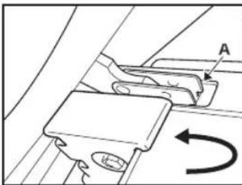
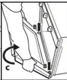
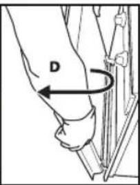
Fig. 1 Fig. 2
MOVING THE UPPER HEATING ELEMENT (ONLY ON CERTAIN MODELS)
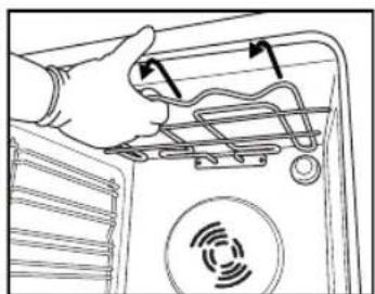
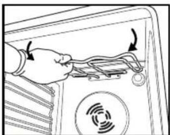
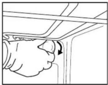
Fig. 6 Fig. 7
NOTE:
Fig. 9
Drip tray (Fig. 1)
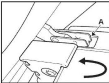
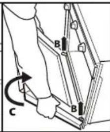
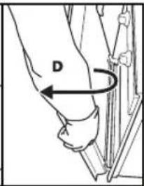
Fig. 1 Fig. 2
MOVING THE UPPER HEATING ELEMENT (ONLY ON CERTAIN MODELS)
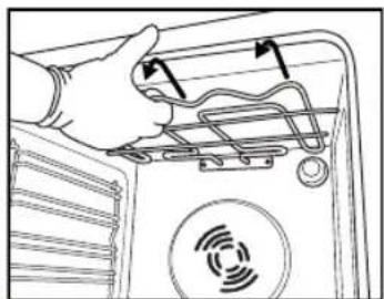
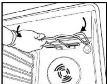
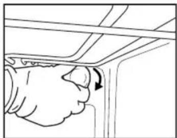
Fig. 6 Fig. 7
NOTE:
Fig. 9
Drip tray (Fig. 1)
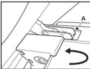
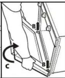
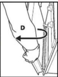
Fig. 1 Fig. 2
MOVING THE UPPER HEATING ELEMENT (ONLY ON SOME MODELS)
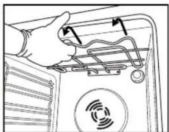
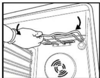
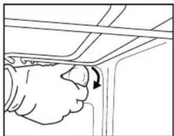
Fig. 6 Fig. 7
NOTE:
Fig. 9
Drip tray (Fig. 1)
TROUBLESHOOTING GUIDE
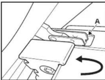
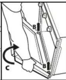
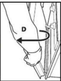
Fig. 1 Fig. 2
MOVING THE UPPER HEATING ELEMENT (ONLY ON SOME MODELS)
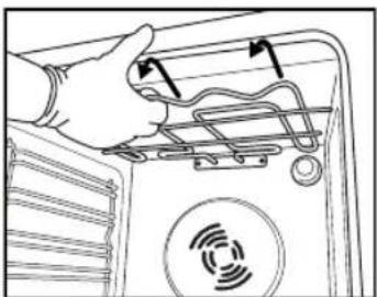
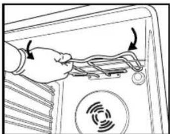
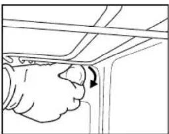
Fig. 6 Fig. 7
NOTE:
Fig. 9
Drip tray (Fig. 1)
YOUR SAFETY AND THE SAFETY OF OTHERS IS VERY IMPORTANT
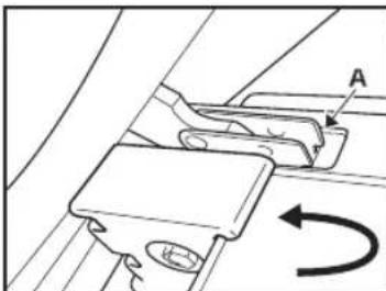
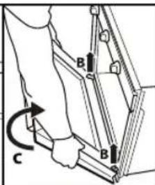
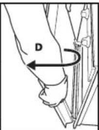
Fig. 1 Fig. 2
REMOVING THE UPPER HEATING ELEMENT (ONLY IN SOME MODELS)
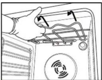
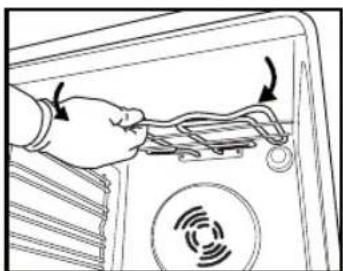
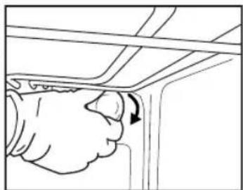
Fig. 6 Fig. 7
NOTE:
Fig. 9
Drip tray (Fig. 1)

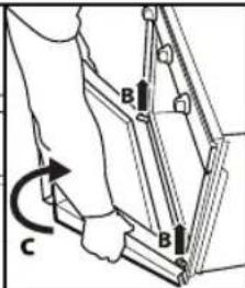
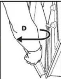
Fig. 1 Fig. 2
REMOVING THE UPPER HEATING ELEMENT (ONLY IN SOME MODELS)
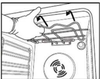
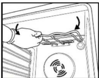
Fig. 3 Fig. 4 Fig. 5
REPLACING THE OVEN LIGHT BULB
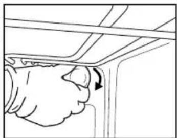
Fig. 6 Fig. 7
NOTE:
SUITABLE ACCESSORIES
Fig. 9
Deep baking tray (Fig. 1)
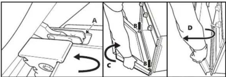
Fig. 1 Fig. 2
REMOVING THE UPPER HEATING ELEMENT (ONLY ON SOME MODELS)
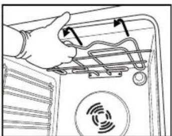
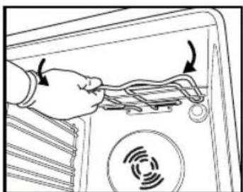
Fig. 3 Fig. 4 Fig. 5
REPLACING THE OVEN LIGHT BULB
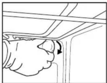
Fig. 6 Fig. 7
NOTE:
Fig. 9
- Fig. 2
MOVING THE UPPER HEATING ELEMENT (ONLY ON CERTAIN MODELS)
- Fig. 7
NOTE:
- Fig.
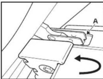
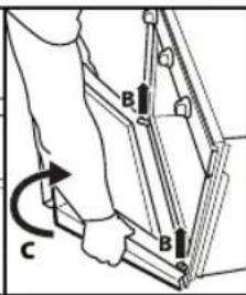
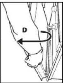
Fig. 1 Fig. 2
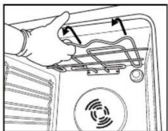
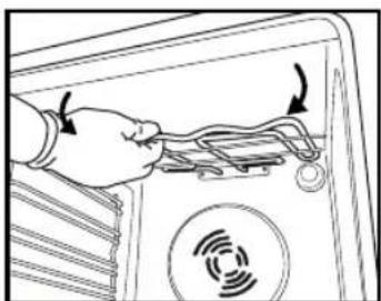
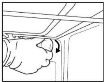
Fig. 6 Fig. 7
NOTE:
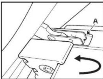
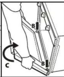
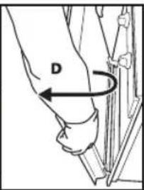
Fig. 1 Fig. 2
MOVING THE UPPER HEATING ELEMENT (ONLY ON SOME MODELS)
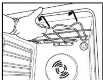
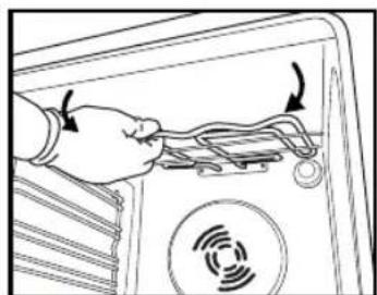
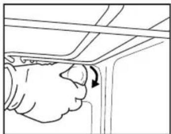
Fig. 6 Fig. 7
WARNING:
Fig. 9
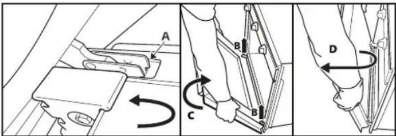
Fig. 1 Fig. 2
MOVING THE UPPER HEATING ELEMENTS (ONLY ON SOME MODELS)
- Remove the side accessory grilles (fig. 3).
- Slightly pull out the heating element (fig. 4) and then lower it (fig. 5).
- Install the heating element in its position by lifting it, gently pulling it towards you, and checking that it rests on the side supports.
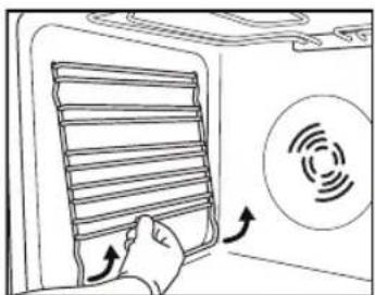
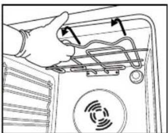
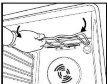
Fig. 3 Fig. 4 Fig. 5
REPLACING THE OVEN LIGHT BULB
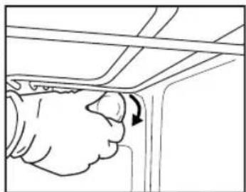
Fig. 6 Fig. 7
NOTE:
Fig. 9
Preheat pan (Fig. 1)
- Function selection knob
- Thermostat knob
- Red thermostat indicator light
USING THE OVEN
IMPORTANT SAFETY INSTRUCTIONS
YOUR SAFETY AND THE SAFETY OF OTHERS IS VERY IMPORTANT
This manual and the device itself provide important safety warnings that must be read and always followed.

This is the danger symbol, which relates to safety and warns users of potential hazards to themselves and others.
All safety warnings are preceded by the danger symbol and the following terms:

DANGER
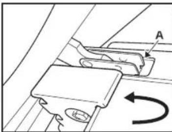
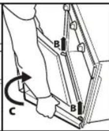
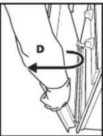
Fig. 1 Fig. 2
MOVING THE UPPER HEATING ELEMENT (ONLY SOME MODELS)
- Remove the side racks – supports for additional accessories (fig. 3).
- Gently pull out the heater (fig. 4) and lower it (fig. 5).
- To reposition the heater, lift it slightly by pulling it towards you and make sure it sits on the side supports.
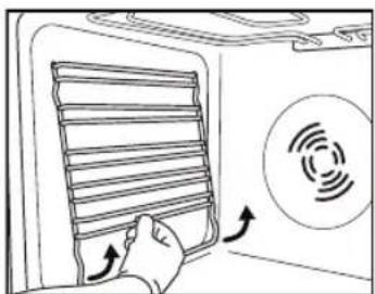
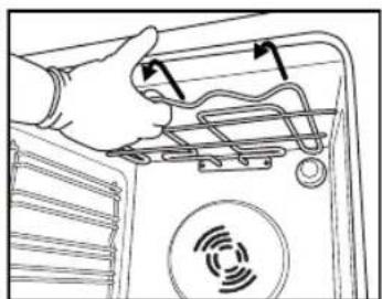
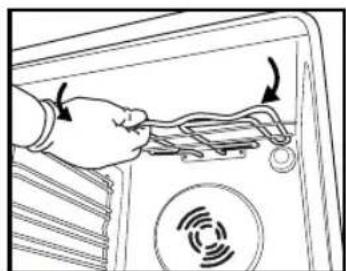
Fig. 3 Fig. 4 Fig. 5
REPLACING THE OVEN LIGHT BULB
To replace the rear light bulb (if present):
- Disconnect the oven from the power supply.
- Unscrew the bulb cover (fig. 6), replace the bulb (see note on bulb type) and screw the cover back on (fig. 7).
- Reconnect the oven to the power supply.
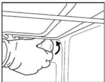
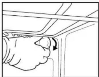
Fig. 6 Fig. 7
NOTE:
- Use only 25-40 W/230 V bulbs, type E-14, T300°C.
- Bulbs can be purchased from our Technical Assistance Service.
IMPORTANT:
- Do not operate the oven before replacing the bulb cover.
INSTRUCTIONS FOR USING THE OVEN
FOR ELECTRICAL CONNECTION, SEE THE SECTION ON INSTALLATION
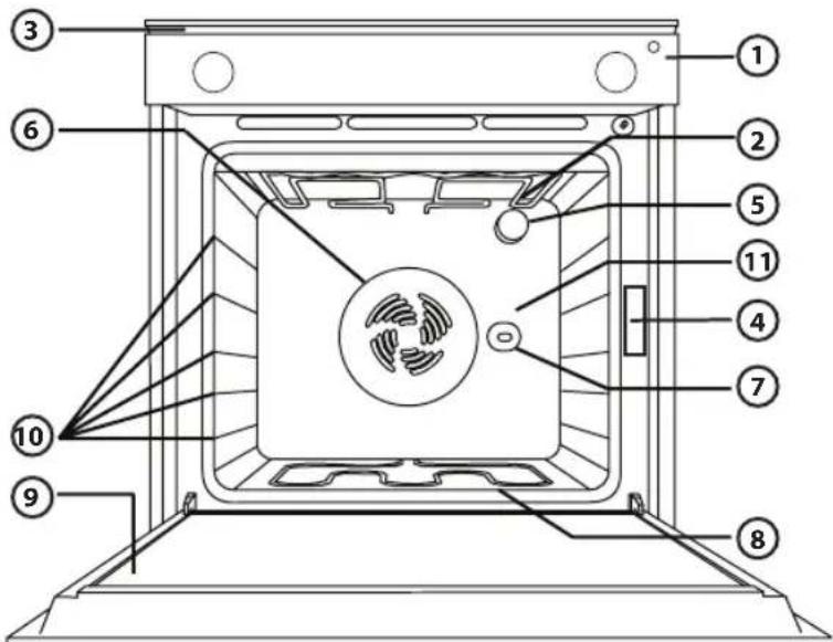
Fig. 9
- Function selector knob
- Thermostat knob
- Red thermostat indicator light.
HOW TO USE THE OVEN
Turn the function selector knob to the desired function.
IMPORTANT SAFETY INSTRUCTIONS
YOUR SAFETY AND THE SAFETY OF OTHERS ARE VERY IMPORTANT
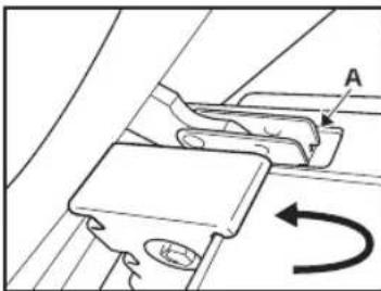
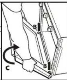
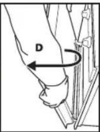
Figure 1 Figure 2
MOVING THE UPPER HEATING ELEMENT (ONLY ON SOME MODELS)
- Remove the side racks for holding accessories (figure 3).
- Pull the heating element slightly (figure 4) and lower it (figure 5).
- To reposition the heating element, lift it up with a slight pull towards you, and make sure it rests on the side supports.
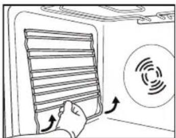
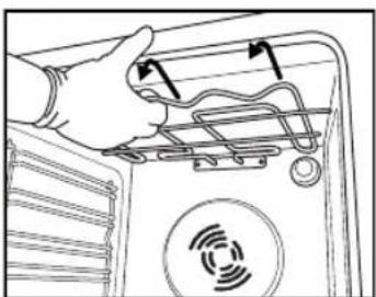
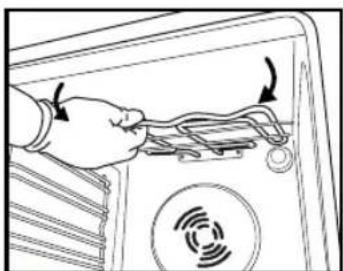
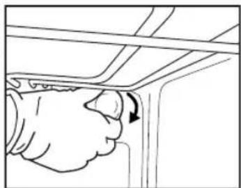
Figure 6 Figure 7
NOTE:
- Use only an incandescent bulb of 25-40W/230V type E-14, T300°C.
- Bulbs can be obtained from our Service Department.
IMPORTANT:
- Control panel
- Upper heating element/grill
- Cooling system (if present)
- Rating plate (must not be removed)
- Indicator light
- Ventilation system for baking (if present)
- Rotisserie (if present)
- Lower heating element (not visible)
- Door
- Shelf positions
- Rear wall
NOTE:
- After baking is finished, once the oven is turned off, the cooling fan may continue to run for some time.
COMPATIBLE ACCESSORIES
(for accessories supplied with the oven, see technical data)
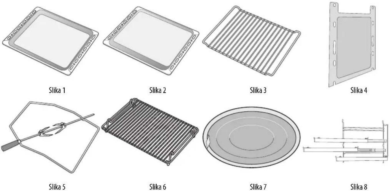
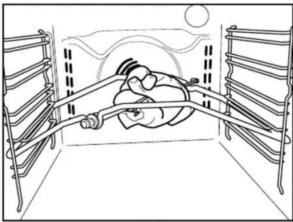
Figure 9
- Function selector knob
- Thermostat knob
- Red thermostat LED.
HOW TO USE THE OVEN
Turn the function selector to the desired function.
The oven light turns on. Turn the thermostat knob clockwise to the desired temperature.
The red LED turns on, and turns off again when the oven has heated to the selected temperature.
At the end of baking, turn the knobs to "0".
FUNCTION DESCRIPTION TABLE

- LOWERING THE UPPER GRILL ELEMENT (ONLY ON SOME MODELS)
- NOTE
- DRIP TRAY (FIG. 1)
- IMPORTANT SAFETY INSTRUCTIONS
- YOUR SAFETY AND THAT OF OTHERS IS VERY IMPORTANT
- DANGER
- WARNING
- SCRAPPING OF HOUSEHOLD APPLIANCES
- INSTALLATION
- PREPARING THE HOUSING UNIT
- ELECTRICAL CONNECTION
- GENERAL RECOMMENDATIONS
- BEFORE USE
- DURING USE
- SAFEGUARDING THE ENVIRONMENT
- DISPOSAL OF PACKING MATERIAL
- SCRAPPING THE PRODUCT
- ENERGY SAVING
- DECLARATION OF CONFORMITY C€
- TROUBLESHOOTING GUIDE
- THE OVEN DOES NOT WORK
- THE DOOR WILL NOT OPEN
- THE ELECTRONIC PROGRAMMER DOES NOT WORK
- AFTER-SALES SERVICE
- BEFORE CALLING THE AFTER-SALES SERVICE
- SERVICE
- CLEANING
- OVEN EXTERIOR
- OVEN INTERIOR
- ACCESSORIES
- MAINTENANCE
- REMOVING THE DOOR
- TO REMOVE THE DOOR
- TO REFIT THE DOOR
- MOVING THE TOP HEATING ELEMENT (SOME MODELS ONLY)
- N.B
- IMPORTANT
- INSTRUCTIONS FOR OVEN USE
- FOR ELECTRICAL CONNECTION, SEE THE PARAGRAPH ON INSTALLATION
- COMPATIBLE ACCESSORIES
- DRIP-TRAY (FIG. 1)
- BAKING TRAY (FIG. 2)
- WIRE SHELF (FIG. 3)
- CATALYTIC SIDE PANELS (FIG. 4)
- TURNSPIT (FIG. 5)
- GRILL PAN SET (FIG. 6)
- GREASE FILTER (FIG. 7)
- SLIDING SHELVES (FIG. 8)
- HOW TO READ THE COOKING TABLE
- COOKING DIFFERENT FOODS AT THE SAME TIME
- DESSERTS
- MEAT
- TURNSPIT (ONLY IN SOME MODELS)
- PIZZA
- RISING FUNCTION (PRESENT ONLY IN SPECIFIC MODELS)
- MOVING THE UPPER HEATING ELEMENT (ONLY ON CERTAIN MODELS)
- MOVING THE UPPER HEATING ELEMENT (ONLY ON SOME MODELS)
- YOUR SAFETY AND THE SAFETY OF OTHERS IS VERY IMPORTANT
- REMOVING THE UPPER HEATING ELEMENT (ONLY IN SOME MODELS)
- REPLACING THE OVEN LIGHT BULB
- SUITABLE ACCESSORIES
- DEEP BAKING TRAY (FIG. 1)
- REMOVING THE UPPER HEATING ELEMENT (ONLY ON SOME MODELS)
- MOVING THE UPPER HEATING ELEMENTS (ONLY ON SOME MODELS)
- PREHEAT PAN (FIG. 1)
- USING THE OVEN
- MOVING THE UPPER HEATING ELEMENT (ONLY SOME MODELS)
- TO REPLACE THE REAR LIGHT BULB (IF PRESENT)
- INSTRUCTIONS FOR USING THE OVEN
- FOR ELECTRICAL CONNECTION, SEE THE SECTION ON INSTALLATION
- HOW TO USE THE OVEN
- YOUR SAFETY AND THE SAFETY OF OTHERS ARE VERY IMPORTANT
Brand : IGNIS
Model : AKS 1400
Category : Oven