
AST12UW4RXXQA - Air Conditioning HISENSE - Free user manual and instructions
Find the device manual for free AST12UW4RXXQA HISENSE in PDF.
| Product type | Split air conditioner |
| Brand | Hisense |
| Model | AST12UW4RXXQA |
| Cooling capacity | 12,000 BTU/h (3.5 kW) |
| Heating capacity (heat pump) | 12,000 BTU/h (3.5 kW) |
| Power consumption (cooling) | 1200 W |
| Voltage / Frequency | 230 V ~ 50 Hz |
| Refrigerant | R410A (GWP 1975) |
| Indoor unit dimensions (W x H x D) | 800 x 280 x 200 mm |
| Indoor unit weight | 9 kg |
| Outdoor unit dimensions (W x H x D) | 800 x 550 x 300 mm |
| Outdoor unit weight | 34 kg |
| Indoor unit noise levels | < 40 dB (estimated) |
| Operating modes | Cooling, Heating, Dehumidification, Fan, Auto, Super mode |
| Remote control | Yes, with optional backlit display |
| Air filter | Washable, cleaning indicator after 200 hours |
| Timer | Yes, programmable |
| Auto restart | Yes, after power failure |
| Automatic defrost | Yes, in heating mode |
| Indoor unit fuse | T 3.15A 250V |
| Outdoor unit fuse | T 15A 250V |
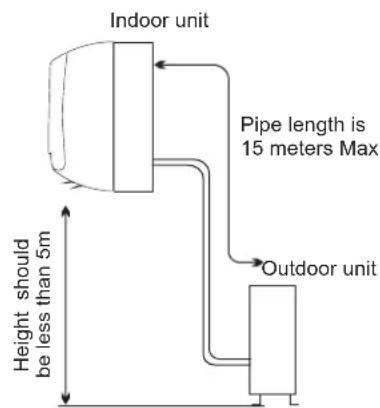
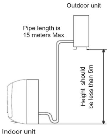
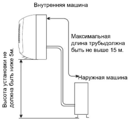
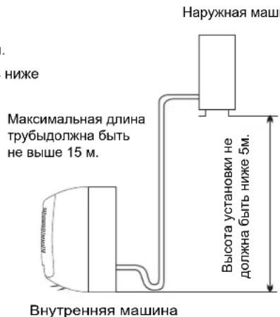
| Maximum piping length | 15 m (5 m without additional refrigerant) |
| Maximum allowable height difference | 5 m |
| Energy efficiency class | A+ (estimated) |
Frequently Asked Questions - AST12UW4RXXQA HISENSE
User questions about AST12UW4RXXQA HISENSE
0 question about this device. Answer the ones you know or ask your own.
Ask a new question about this device
Download the instructions for your Air Conditioning in PDF format for free! Find your manual AST12UW4RXXQA - HISENSE and take your electronic device back in hand. On this page are published all the documents necessary for the use of your device. AST12UW4RXXQA by HISENSE.
USER MANUAL AST12UW4RXXQA HISENSE
USE AND INSTALLATION INSTRUCTIONS
Thank you very much for purchasing this Air Conditioner. Please read this use and installation instructions carefully before installing and using this appliance and keep this manual for future reference.
Contents
safety instructions 1
Preparation before use 2
Safety Precautions 3
Identification of parts 4
Indoor unit 4
Outdoor unit 4
Display introduction 5
Maintenance 6
Protection 7
Troubleshooting 8
Installation instructions 9
Installation diagram 9
Select the installation locations 10
Indoor unit installation 11
Wiring diagram 14
Outdoor unit installation 15
Air purging 15
Remote controller operating instructions. See"remote controller instructions".
Safety instructions
- To guarantee the unit work normally, please read the manual carefully before installation, and try to install strictly according to this manual.
- Do not let air enter the refrigeration system or discharge refrigerant when moving the air conditioner.
- Properly ground the air conditioner into the earth.
- Check the connecting cables and pipes carefully, make sure they are correct and firm before connecting the power of the air conditioner.
- There must be an air-break switch.
- After installing, the consumer must operate the air conditioner correctly according to this manual, keep a suitable storage for maintenance and moving of the air conditioner in the future.
- Fuse of indoor unit: T 3.15A 250V.
For 7k 12k models , f T 15A 250V or T 20A 250V . ~ use of outdoor unit:
For 14k models , f 20A 250V . ~18k use of outdoor unit: T
For 21k 30k models , f T 30A 250V . ~ use of outdoor unit: - A residual current device(RCD)with the rating of above 10mA shall be incorporated in the fixed wiring according to the national rule
- Warning: Risk of electric shock can cause injury or death: Disconnect all remote electric power supplies before servicing.
- The maximum length of the connecting pipe between the indoor unit and outdoor unit should be less than 5 meters. It will affect the efficiency of the air conditioner if the distance longer than that length.
- This appliance can be used by children aged from 8 years and above and persons with reduced physical, sensory or mental capabilities or lack of experience and knowledge if they have been given supervision or instruction concerning use of the appliance in a safe way and understand the hazards involved. Children shall not play with the appliance. Cleaning and user maintenanceshall not be made by children without supervision.
- The batteries in remote controller must be recycled or disposed of properly. Disposal of Scrap Batteries --- Please discard the batteries as sorted municipal waste at the accessible collection point.
- If the appliance is fixed wiring, the appliance must be fitted with means for disconnection from the supply mains having a contact separation in all poles that provide full disconnection under over voltage category III conditions, and these means must be incorporated in the fixed wiring in accordance with the wiring rules.
- If the supply cord is damaged, it must be replaced by the manufacturer, its service agent or similarly qualified persons in order to avoid a hazard.
- The appliance shall be installed in accordance with national wiring regulations.
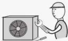
The air conditioner must be installed by professional or qualified persons. - The appliance shall not be installed in the laundry.
Preparation before use
Note

-
When charging refrigerant into the system, make sure to charge in liquid state, if the refrigerant of the appliance is R410A. Otherwise, chemical composition of refrigerant (R410A) inside the system may change and thus affect performance of the air conditioner.
-
According to the character of refrigerant (R410A, the value of GWP is 1975), the pressure of the tube is very high, so be sure to be careful when you install and repair the appliance.
-
If the supply cord is damaged, it must be replaced by the manufacturer, its service agent or similarly qualified persons in order to avoid a hazard.
The air conditioner must be installed by a professional engineer.
- The temperature of refrigerant circuit will be high, please keep the interconnection cable away from the copper tube.

Preset
Before using the air conditioner, be sure to check and preset the following.
- Remote Control presetting
Each time after the remote control is replaced with new batteries or is energized, rautotpresettig heat pump.If the air conditioner you purchased is a Cooling Only one, heat pump remote controller can also be used.
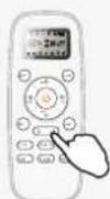
- Back-light function (optional) of Remote Control
Hold down any button on remote control to activate the back light. It automatically shuts off 10 seconds later.
Note: Back-light is an optional function.
- Auto Restart Presetting
The air conditioner has an Auto-Restart function.
Safeguarding the environment
This appliance is made of recyclable or re-usable material. Scrapping must be carried out in compliance with local waste disposal regulations. Before scrapping it, make sure to cut off the mains cord so that the appliance cannot be re-used.
For more detailed information on handling and recycling this product, contact your local authorities who deal with the separate collection of rubbish or the shop where you bought the appliance.
SCRAPPING OF APPLIANCE
This appliance is marked according to the European Directive 2002/96/EC, Waste Electrical and Electronic Equipment (WEEE).
This marking indicates that this product should not be disposed with other household wastes throughout the EU. To prevent possible harm to the environment or human health from uncontrolled waste disposal,recycle it responsibly to promote the sustainable reuse of material resources. To return your used device, please use the return and collection systems or contact the retailer where the product was purchased. They can take this product for environmental safe recycling.
Safety precautions
Symbols in this Use and Care Manual are interpreted as shown below.

Be sure not to do.

Grounding is essential.

Pay attention to such a situation.

Warning: Incorrect handling could cause a serious hazard, such as death, serious injury, etc.

Use correct power supply in accordance with the rating plate requirement. Otherwise, serious faults or hazard may occur or a fire maybe break out.
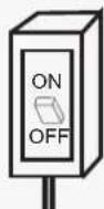

Keep the power supply circuit breaker or plug from dirt. Connect the power supply cord to it firmly and correctly, lest an electric shock or a fire break out due to insufficient contact.
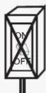


Do not use the power supply circuit breaker or pull off the plug to turn it off during operation. This may cause a fire due to spark, etc.

It is the user's responsibility to make the appliance be grounded according to local codes or ordinances by a licenced technician.

It is harmful to your health if the cool air reaches you for a long time. It is advisable to let the air flow be deflected to all the room.
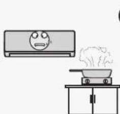
Prevent the air flow from reaching the gas burners and stove.
Do not touch the operation buttons when your hands are wet.

Turn off the appliance by remote control firstly before cutting off power supply if malfunction occurs.

Never insert a stick or similar obstacle to the unit. Since the fan rotates at high speed, this may cause an injury.

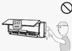
Do not repair the appliance by yourself. If this is done incorrectly, it may cause an electric shock, etc.

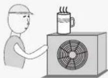
Do not put any objects on the outdoor unit.
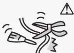
Do not knit, pull or press the power supply cord, lest the power supply cord be broken. An electric shock or fire is probably caused by a broken power supply cord.
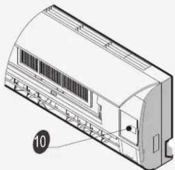
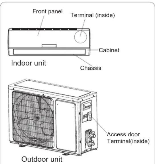
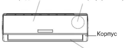
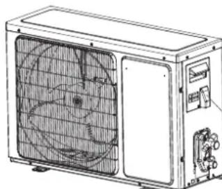
Identification of parts
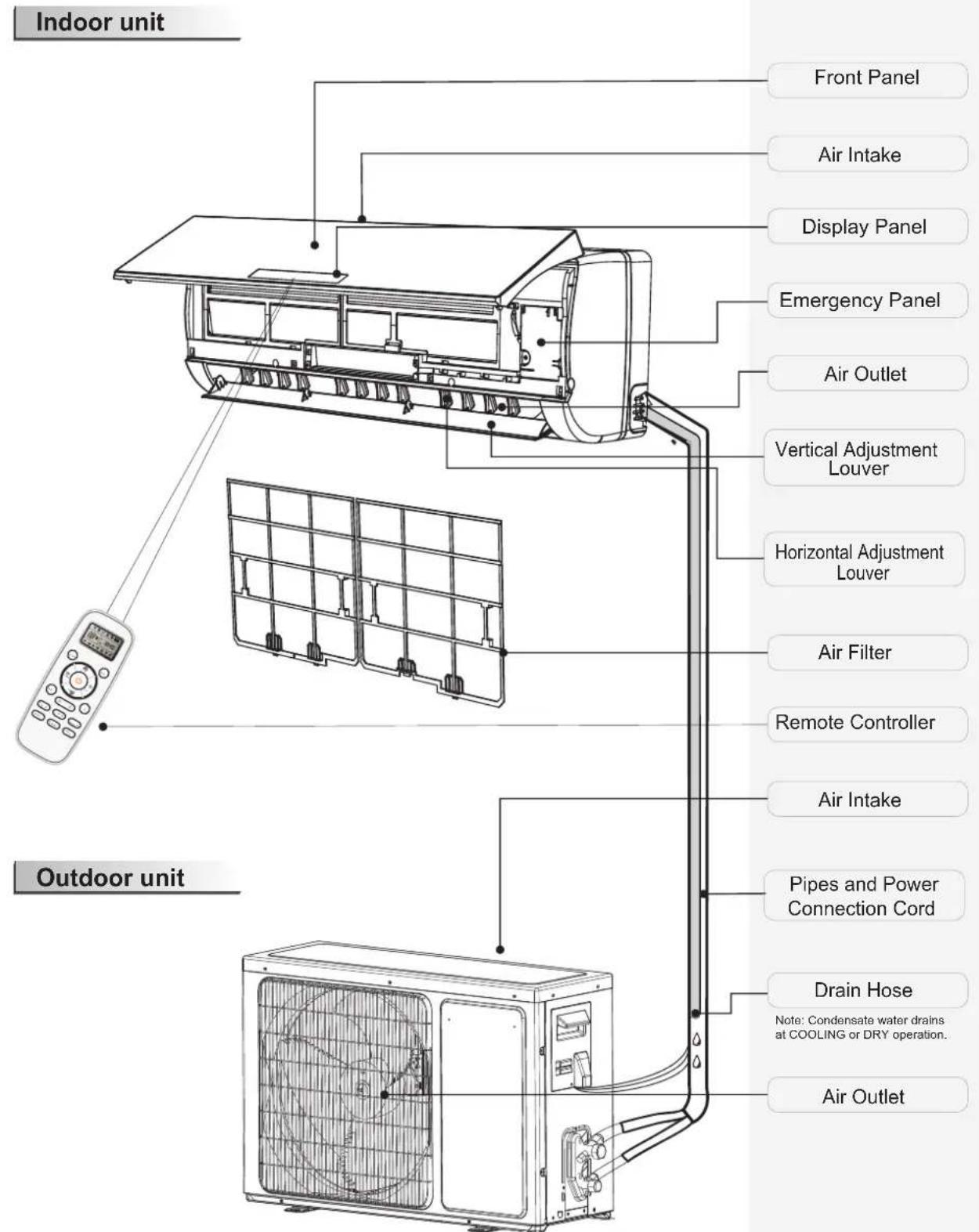
The figures in this manual are based on the external view of a standard model. Consequently, the shape may differ from that of the air conditioner you have selected.
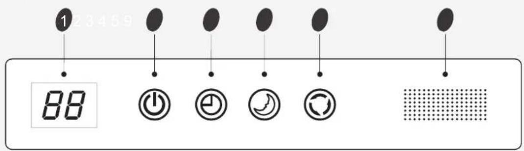
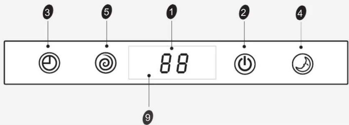
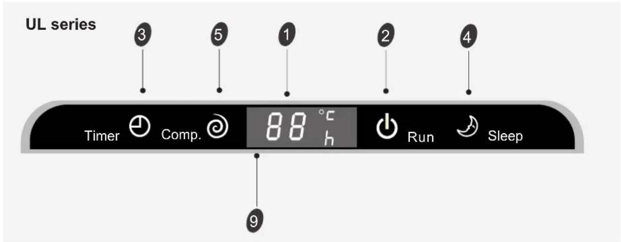
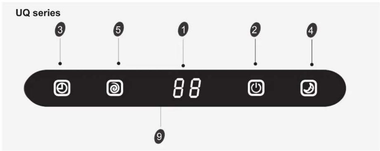
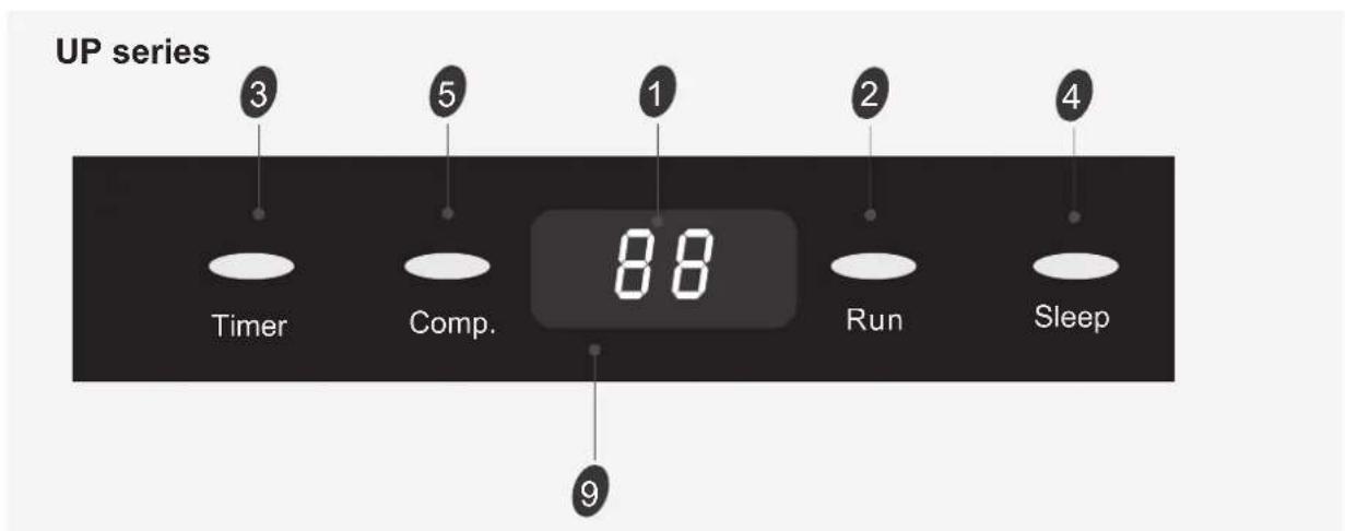
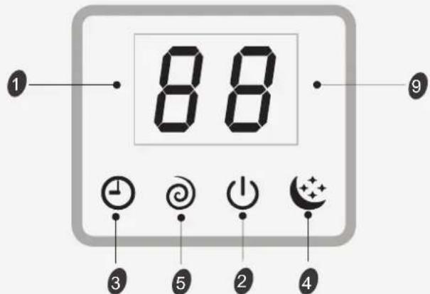
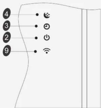
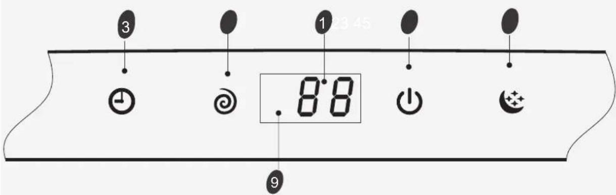
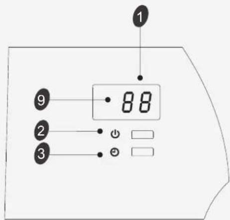
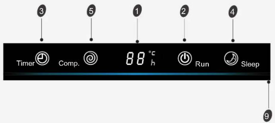
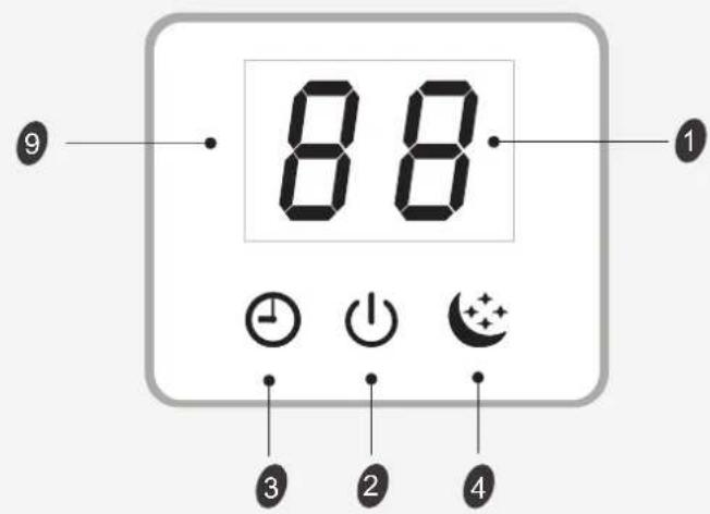
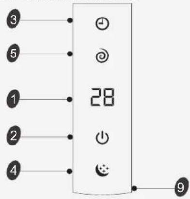
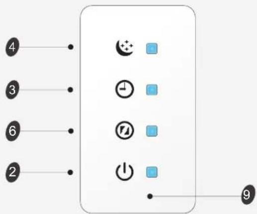
Display introduction

Temperature indicator 1
Display set temperature.
It shows FC after 200 hours of usage as reminder to clean the filter.
After filter cleaning press the filter reset button located on the indoor unit behind the front panel in order to reset the display. (optional)


Running indicator 2
It lights up when the AC is running.
It flashes during defrosting.


Timer indicator 3
It lights up during set time.


Sleep indicator 4
It lights up in sleep mode.


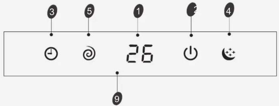
Compressor indicator 5
It lights up when the compressor is on.


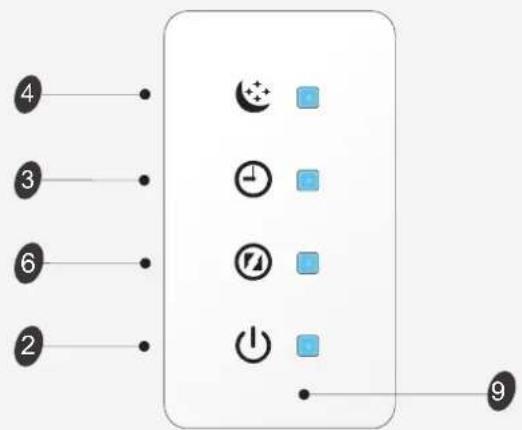
Super indicator 6
It lights up in super mode.
Mode indicator
Heating displays orange, others display white

Fan speed indicator 8
Signal Receptor 9
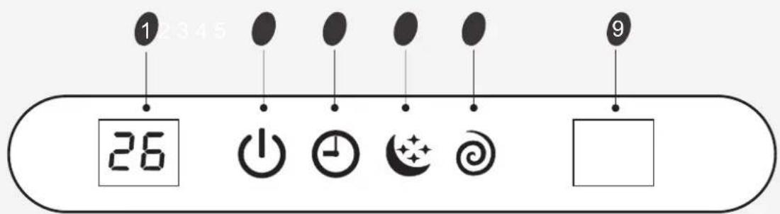
VG/VL series
The symbols may be different from these models, but the functions are similar.
Display introduction
VT series
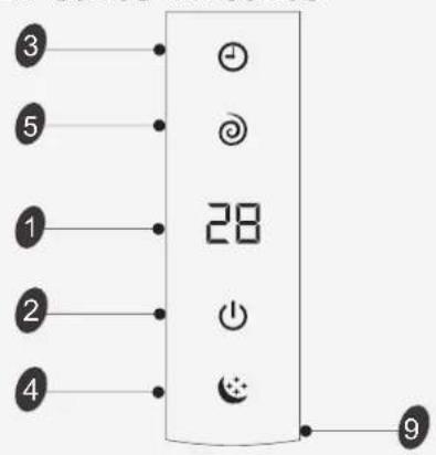
SF series/DG(Right side)
SE series
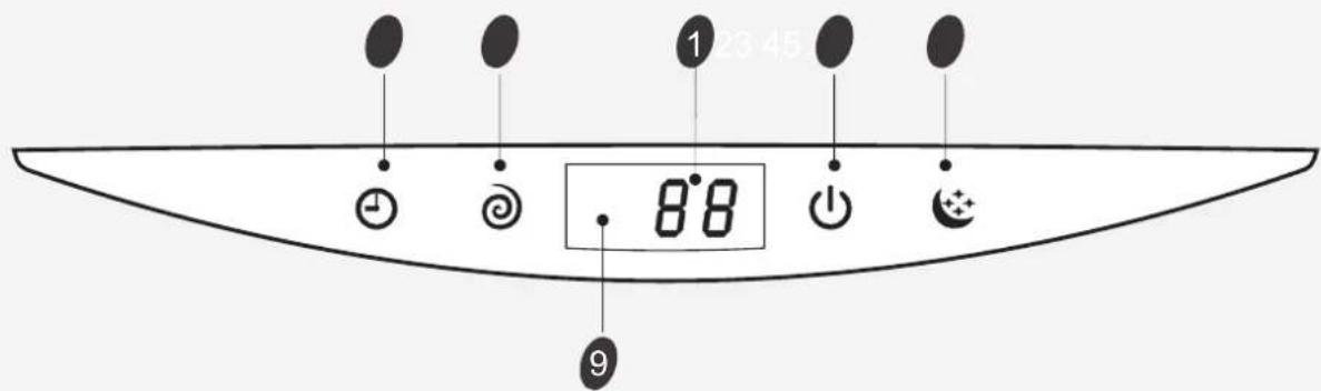
The symbols may be different from these models, but the functions are similar.
Display introduction
The symbols may be different from these models, but the functions are similar.
Display introduction
NS/DE series
NT series
VQ/TE/TF/DA/DG(Middle)/DH series
The symbols may be different from these models, but the functions are similar.
Display introduction
VM series
NM/DF series NK series
TA/TC series

The symbols may be different from these models, but the functions are similar.
Display introduction
VC series
SA/TD/TG/DB/DC series
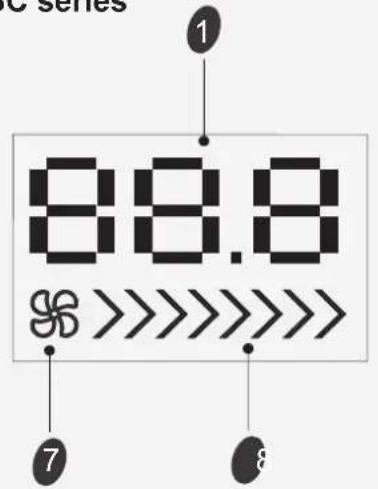
SC series
Emergency button

ON/OFF To let the AC run or stop by pressing the button.
The symbols may be different from these models, but the functions are similar.
Maintenance
Front panel maintenance
| 1 Cut off the power supply Turn off the appliance first before disconnecting from power supply. | 2 Grasp position "a" and pull outward to remove the front panel. |
| 3 Wipe with a soft and dry cloth. Use soft moisture cloth to clean if the front panel is very dirty; | 4 Never use volatile substance such as gasoline or polishing powder to clean the appliance. |
| 5 Never sprinkle water onto the indoor unit | 6 Reinstall and shut the front panel. Reinstall and shut the front panel by pressing position "b" downward. |
Air filter maintenance
| 1 Stop the appliance and remove the air filter. 1 Open the front panel. 2 Press the handle of the filter gently from the front. 3. Grasp the handle and slide out the filter. | 2 Clean and reinstall the air filter. If the dirt is conspicuous, wash it with a solution of detergent in lukewarm water. After cleaning, dry well in shade. |
| 3 Close the front panel again. Clean the air filter every two weeks if the air conditioner operates in an extremely dusty environment. | It is necessary to clean the air filter after using it for about 100 hours. |
Protection
Operating condition
The protective device maybe trip and stop the appliance in the cases listed below.
| HEATING | Outdoor air temperature is over 24°C |
| Outdoor air temperature is below -10°C | |
| Room temperature is over 27°C |
| COOLING | Outdoor air temperature is over *43°C |
| Room temperature is below 21°C | |
| DRY | Room temperature is below 18°C |
*For Tropical (T3) Climate condition models, the temperature point is 55^ instead of 43^ . The temperature of some products is allowed beyond the range. In specific situation, please consult the merchant. If the air conditioner runs in COOLING or DRY mode withdoor or window opened for a long time when relative humidity is above 80% , dew may drip down from the outlet.
Noise pollution
- Install the air conditioner at a place that can bear its weight in order to operate more quietly.
- Install the outdoor unit at a place where the air discharged and the operation noise would not annoy your neighbors.
- Do not place any obstacles in front of the air outlet of the outdoor unit lest it increases the noise level.
Features of protector
-
The protective device will work at following cases.
-
Restarting the unit at once after operation stops or changing mode during operation, you need to wait for 3 minutes.
-
Connect to power supply and turn on the unit at once, it may start 20 seconds later.
-
If all operation has stopped, press ON/OFF button again to restart, Timer should be set again if it has been canceled.
Features of HEATING mode
Preheat
At the beginning of the HEATING operation, the airflow from the indoor unit is discharged 2-5 minutes later.
Defrost
In HEATING operation the appliance will defrost (de-ice) automatically to raise efficiency. This procedure usually lasts 2-10 minutes. During defrosting, fans stop operation.
After defrosting completes, it returns to HEATING mode automatically.
Note: Heating is NOT available for cooling only air conditioner models.
Troubleshooting
The following cases may not always be a malfunction, please check it before asking for service.
| Trouble Analysis | |
| Does not run | If the protector trip or fuse is blown. Please wait for 3 minutes and start again, protector device may be preventing unit to work. If batteries in the remote controller exhausted. If the plug is not properly plugged. |
| No cooling or heating air | Is the air filter dirty? Are the intakes and outlets of the air conditioner blocked? Is the temperature set properly? |
| Ineffective control | If strong interference(from excessive static electricity discharge, power supply voltage abnormality) presents, operation will be abnormal. At this time, disconnect from the power supply and connect back 2-3 seconds later. |
| Does not operate immediately | Changing mode during operation, 3 minutes will delay. |
| Peculiar odor | This odor may come from another source such as furniture, cigarette etc, which is sucked in the unit and blows out with the air. |
| A sound of flowing water | Caused by the flow of refrigerant in the air conditioner, not a trouble. Defrosting sound in heating mode. |
| Cracking sound is heard | The sound may be generated by the expansion or contraction of the front panel due to change of temperature. |
| Spray mist from the outlet | Mist appears when the room air becomes very cold because of cool air discharged from indoor unit during COOLING or DRY operation mode. |
| The compressor indicator(red) lights on constantly, and indoor fan stops. | The unit is shifting from heating mode to defrost. The indicator will lights off within ten minutes and returns to heating mode. |
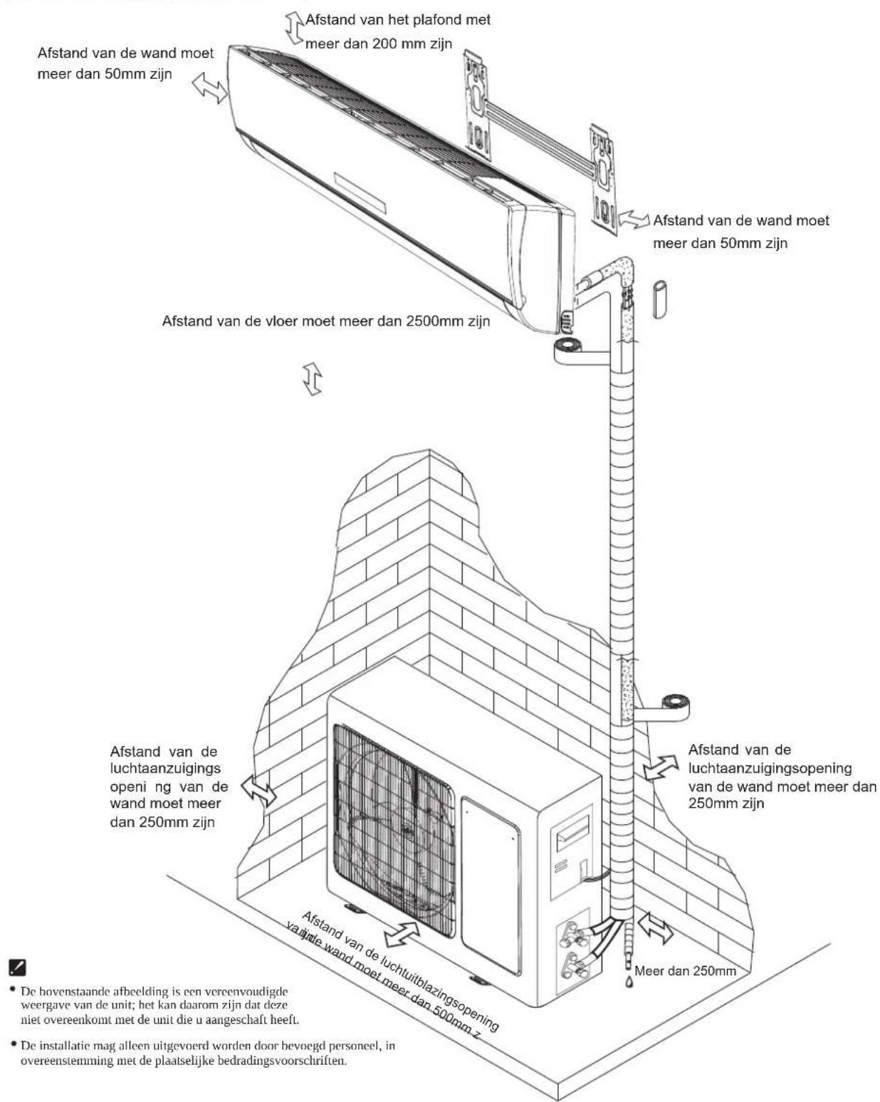
Installation instructions
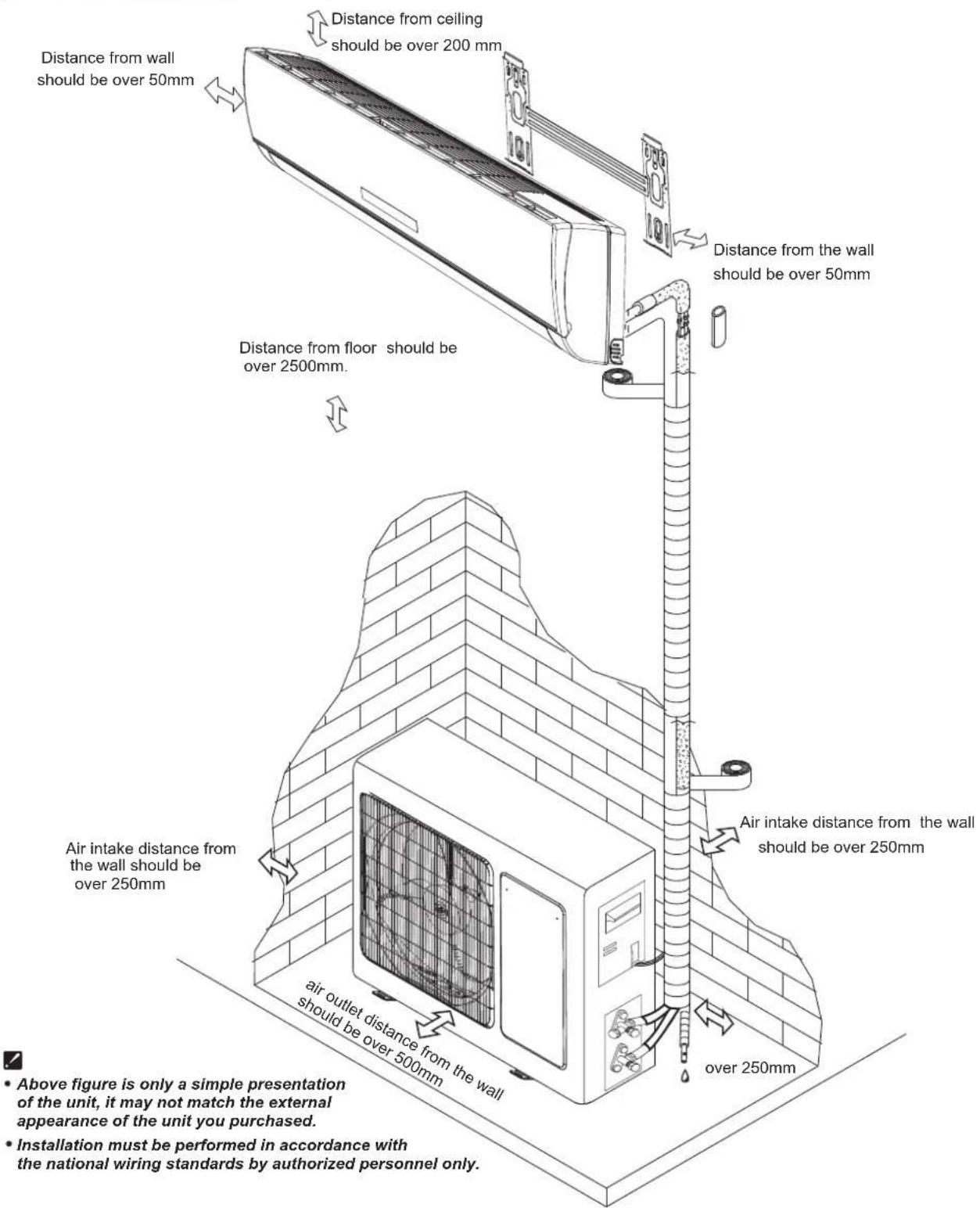
Installation diagram
Installation instructions
Select the installation location
Location for Installing Indoor Unit
- Where there is no obstacle near the air outlet and air can be easily blown to every corner.
- Where piping and wall hole can be easily arranged.
- Keep the required space from the unit to the ceiling and wall according to the installation diagram on previous page.
- Where the air filter can be easily removed.
- Keep the unit and remote controller 1m or more apart from television, radio etc.
- keep as far as possible from fluorescent lamps.
- Do not put anything near the air inlet to obstruct it from air absorption.
Install on a wall that is strong enough to bear the weight of the unit.
Install in a place that will not increase operation noise and vibration - Keep away from direct sunlight and heating sources. Do not place flammable materials or combustion apparatuses on top of the unit.
Location for Installing Outdoor Unit
- Where it is convenient to install and well ventilated.
- Avoid installing it where flammable gas could leak.
- Keep the required distance apart from the wall.
- The distance between Indoor and outdoor unit should be 5 meters and can go up to maximum 15 meters with additional refrigerant charge.
- Keep the outdoor unit away from greasy dirt, vulcanization gas exit.
- Avoid installing it by the roadside where there is a risk of muddy water.
- A fixed base where it is not subject to increased operation noise.
- Where there is not any blockage of the air outlet.
- Avoid installing under direct sunlight, in an aisle or sidewalk, or near heat sources and ventilation fans. Keep away from flammable materials, thick oil fog, and wet or uneven places.
| Model | Max. Allowable Tubing Length at Shipment (m) | Limit of Tubing Length (m) | Limit of Elevation Difference H (m) | Required amount of additional refrigerant (g/m) |
| 7K~18K | 5 | 15 | 5 | 20 |
| 21K 25K~ | 5 | 15 | 5 | 30 |
| 30K | 5 | 15 | 5 | 40 |
If the height or pipe length is out of the scope of the table, please consult the merchant.
Installation instructions
Indoor unit installation
1. Installing the Mounting Plate
- Decide an installing location for the mounting plate according to the indoor unit location and piping direction.
- Keep the mounting plate horizontal with a horizontal ruler or dropping line.
- Drill holes of 32mm in depth on the wall for fixing the plate.
- Insert the plastic plugs to the hole, fix the mounting plate with tapping screws.
- Inspect if the mounting plate is well fixed. Then drill a hole for piping.
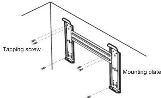
Note: The shape of your mounting plate may be different from the one above, but the installation method is similar. Note: As the above figure shown, the six holes matched with tapping screw on the mounting plate must be used to fix the mounting plate, the others are prepared.
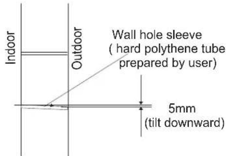
2. Drill a Hole for Piping
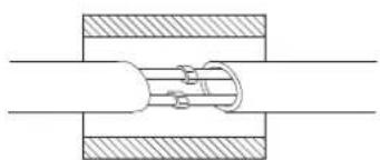
- Decide the position of the hole for piping according to the location of mounting plate.
- Drill a hole in the wall. The hole should tilt a little downward toward outside.
- Install a sleeve through the wall hole to keep the wall tidy and clean.
3. Indoor Unit Piping Installation
- Put the piping (liquid and gas pipe) and cables through the wall hole from outside or put them through from inside after indoor piping and cables connection is complete to connect to the outdoor unit.
- Decide whether to saw the unloading piece off in accordance with the piping direction.(as shown below)
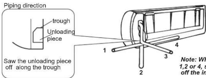
Note: When installing the pipe at the directions 1,2 or 4, saw the corresponding unloading piece off the indoor unit base.
- After connecting the piping, install the drain hose. Then connect the power cords. After connecting, wrap the piping, cords and drain hose together with thermal insulation materials.
Installation instructions
- Piping Joints Thermal Insulation:
Wrap the piping joints with thermal insulation materials and then wrap with a vinyl tape.
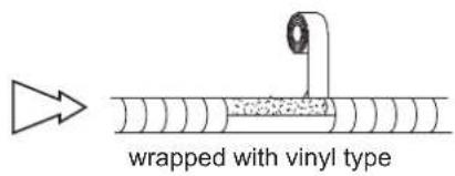
Thermal insulation
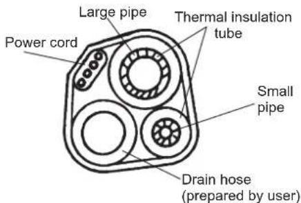
- Piping Thermal Insulation:
a. Place the drain hose under the piping.
b. Insulation material uses polythene foam over 6mm in thickness.
Note: Drain hose is prepared by user.
- Do not arrange the drain pipe in a way that leaves it twisted, sticking out or waving around. Do not immerse the end of it in water.
- If an extension drain hose is connected to the drain pipe, make sure to insulated when passing along the indoor unit.
- When the piping is directed to the right, piping, power Cord and drain pipe should be thermal insulated and fixed onto the back of the unit with a piping fixer.
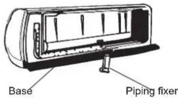
A. Insert the pipe fixer to the slot.
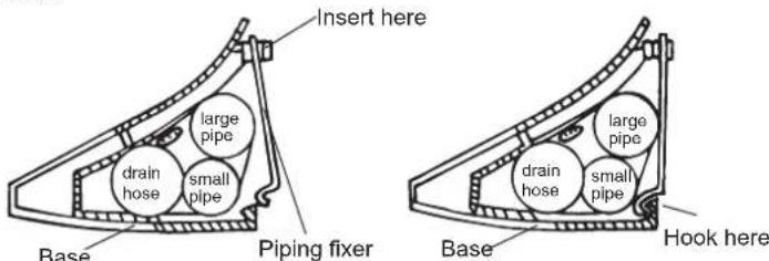
B. Press to hook the pipe fixer onto the base.
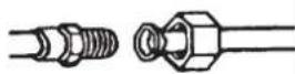
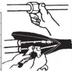
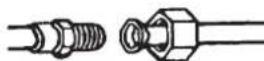
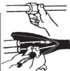
Piping Connection:
a. Connect indoor unit pipes with two wrenches. Pay special attention to the allowed torque as shown below to prevent the pipes, connectors and flare nuts from being deformed and damaged.
b. Pre-tighten them with fingers at first, then use the wrenches.
| Model | Pipe size | Torque | Nut width | Min.thickness |
| 7,8,9,10,12,14,18K | Liquid Side ( 1/4 inch) φ6mm or | 15~20N·m | 17mm | 0.5mm |
| 18K*,21,22,24,25,30K | Liquid Side ( 3/8 inch) φ9.53mm or | 30~35N·m | 22mm | 0.6mm |
| 7,8,9,10,12K | Gas Side ( 3/8 inch) φ9.53mm or | 30~35N·m | 22mm | 0.6mm |
| 12K*,14K,18K | Gas Side ( inch) φ12mm or 1/2 | 50~55N·m | 24mm | 0.6mm |
| 18K*,21,22,24,25,30K | Gas Side ( 5/8 inch) φ16mm or | 60~65N·m | 27mm | 0.6mm |
*The unit of 12 K^ * is bigger than the unit of 12 K . The unit of 18 K^ * is bigger than the unit of 18 K .
Installation instructions
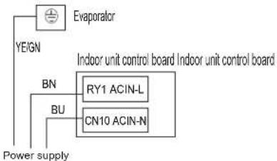
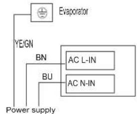
4. Connecting of the Cable
- Indoor Unit
Connect the power cord to the indoor unit by connecting the wires to the terminals on the control board individually in accordance with the outdoor unit connection.
Note: For some models, it is necessary to remove the cabinet to connect to the indoor unit terminal.
- Outdoor Unit
1) Remove the access door from the unit by loosening the screw. Connect the wires to the terminals on the control board individually as follows.
2) Secure the power cord onto the control board with cable clamp.
3) Reinstall the access door to the original position with the screw.
4) Use a recognized circuit breaker for 24K model between the power source and the unit. A disconnecting device to adequately disconnect all supply lines must be fitted.
The figures in this manual are based on the external view of a standard model. Consequently, the shape may differ from that of the air conditioner you have selected.
Caution:
- Never fail to have an individual power circuit specifically for the air conditioner. As for the method of wiring, refer to the circuit diagram posted on the inside of the access door.
- Confirm that the cable thickness is as specified in the power source specification.
- Check the wires and make sure that they are all tightly fastened after cable connection.
- Be sure to install an earth leakage circuit breaker in wet or moist areas.
Cable Specifications
| Capacity (Btu/h) | Power cord | Power connecting cord | ||
| Normal cross - sectional area | Type Type | Normal cross - sectional area | ||
| 7K~12K | H07RN-F | H07RN/F.5X3 | 1.0 mm X5/1.5 | |
| 7 12K*~ K* | 1.0/1.5mmX3 | H07RN-FH | 0.50A-5mmX4 | |
| 14K~18K | H07RN-F | 1.5mmX3 | H07RN-F | 1.5mmX5 |
| 14K*~ K*18 | H05VV-F | 1.5/2.5mmX3 | H07RN-F | 1.5mmX4 |
| 21K~30K | H07RN-F | 2.5mmX3 | H07RN-F | 0.75mmX4 |
| H07RN-F | 2.5mmX3 | H07RN-F | 2.5mmX5 | |
| 21K*~30K* | 2.5mmX3 | H07RN-FH | 0.5x5mmX4 | |
NOTE: K^ means the this model comes from indoor unit.power supply of
Attention:
The plug must be accessible even after the installation of the appliance in case there is a need to disconnect it. If not possible, connect appliance to a double-pole switching device with contact separation of at least 3mm^2 placed in an accessible position even after installation.
Installation instructions
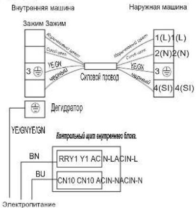
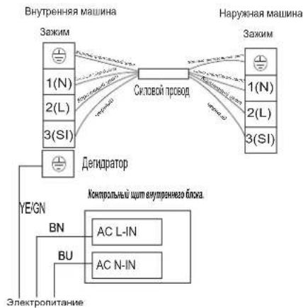
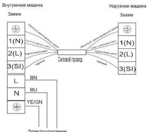
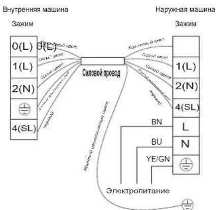
Wiring diagram
Make sure that the color of the wires in the outdoor unit and terminal No. are the same as those of the indoor unit.
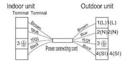
- 7K12K Model~
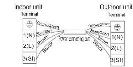
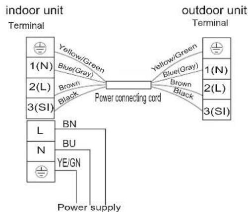
- 14K^30K^ Model~
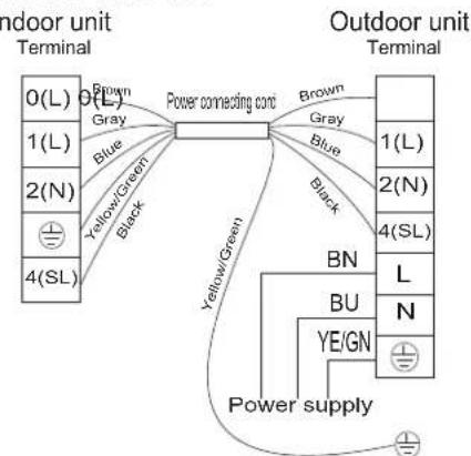
- 7K 30K Model~
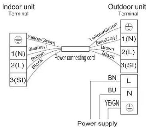
For * models, the power supply is connected from the indoor unit with a circuit breaker. The diagram is reference only, and the actual terminal shall prevail.
Installation instructions
Outdoor unit installation
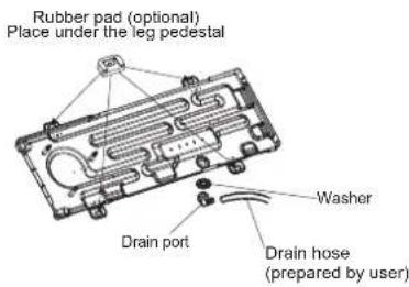
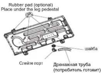
- Install Drain Port and Drain Hose (for heat-pump model only)
The condensate drains from the outdoor unit when the unit operates in heating mode. In order not to disturb your neighbor and protect the environment, install a drain port and a drain hose to direct the condensate water. Just install the drain port and rubber washer to the chassis of the outdoor unit, then connect a drain hose to the port as the right figure demonstrates.
- Install and Fix Outdoor Unit
Fix with bolts and nuts tightly on a flat and strong floor.
If installed on the wall or roof, make sure to fix the supporter well to prevent it from shaking due to serious vibration or strong wind.
-
Outdoor Unit Piping Connection
-
Remove the valve caps from the 2-way and 3-way valve.
-
Connect the pipes to the 2-way and 3-way valves separately according to the required torque.
-
Outdoor Unit Cable Connection (see previous page)
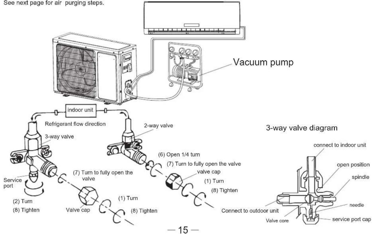
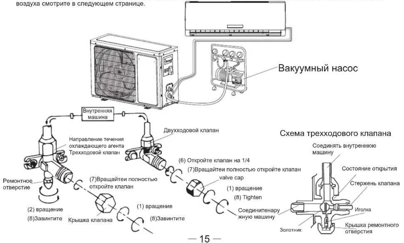
Air purging
The air which contains moisture remaining in the refrigeration cycle may cause a malfunction on the compressor. After connecting the indoor and outdoor units, release air and moisture from the refrigerant cycle using a vacuum pump, as shown below.
Note: To protect the environment, be sure not to discharge the refrigerant to the air directly.
See next page for air purging steps.
Installation instructions
How to Purge Air Tubes:
(1) Unscrew and remove caps from 2 and 3-way valves.
(2) Unscrew and remove cap from service valve.
(3) Connect vacuum pump flexible hose to the service valve.
(4) Start vacuum pump for 10-15 minutes until reaching a vacuum of 10mmHg absolutes.
(5) With vacuum pump still running close the low pressure knob on vacuum pump manifold. Then stop the vacuum pump.
(6) Open 2-way valve, 1/4 turn, then close it after 10 seconds. Check tightness of all joints using liquid soap or an electronic leak detector.
(7) Turn 2 and 3-way valves stem to fully close the valves. Disconnect the flexible vacuum pump hose.
(8) Replace and tighten all valve caps.
Hisense
No teja, tire o presione el cable de alimentacion, de lo contrario el cable de alimentacion可以选择 dañarse. Una descarga electrica o un incendioSEO:SEOSEOSEOSEOSEOSEOSEOSEOSEOSEOSEOSEOSEOSEOSEOSEOSEOSEOSEOSEOSEOSEOSEOSEOSEOSEOSEOSEOSEOSEOSEOSEOSEOSEOSEOSEOSEOSEOSEOSEOSEOSEOSEOSEOSEOSEOSEOSEOSEOSEOSEOSEOSEOSEOSEOSEOSEOSEOSEOSEOSEOSEOSEOSEOSEOSEOSEOSEOSEOSEOSEOSEOSEOSEOSEOSEOSEOSEOSEOSEOSEOSEOSEOSEOSEOSEOSEOSEOSEOSEOSEOSEOSEOSEOSEOSEOSEOSEOSEOSEO SEOEO SEOEO SEOEO SEOEO SEOEO SEOEO SEOEO SEOEO SEOEO SEOEO SEOEO SEOEO SEOEO SEOEO SEOEO SEOEO SEOEO SEOEO SEOEO SEOEO SEOEO SEOEO SEOEO SEOEO SEOEO SEOEO SEOEO SEOEO SEOEO SEOEO SEOEO SEOEO SEOEO SEOEO SEOEO SEOEO SEOEO SEOEO SEOEO SEOEO SEOEO SEOEO SEOEO SEOEO SEOEO SEOEO SEOEO SEOEO SEOEO SEOEO SEOEQ
Safeguarding the environment
Manutenção do painei frontal
A Harding is essentieel.

VQ/TE/TF/DA/DG(Middle)/DH series

NM/DF series NK series

TA/TC series
Installatie-instructions
Installatie diagram
Installatie-instructions
Installatie-instructions
3. Indoor Unit Piping Installation
Installatie-instructions

Installatie-instructions
Installatie-instructions
Bedrangdisdiagram
Installatie-instructions
Preparation pre-installation 2
Pollution sonore
Bb6op MeCTa yCTaHOBKn 10
MOHTaX BHyTpEHHeMaUHbI 11
Cxema coeHHene 14
MoHTaX HapyKHOI MaunHbI 15
BbInyck Bo3dyxa 15
ycnoBne pa6oTbI
B cIeIyIOx yCIOBnX, 3aIHTHOe yCTPOJCTBO MOKeT OTKJIIOHTb N OCTaHOBTb DaHHbIKoHdNtioHep.
| HarpeB | Temnepatypa Bo3dya BHe NOMESEHIN BbIe 24C |
| Temnepatypa Bo3dya BHe NOMESEHIN HIXe -10C | |
| KomHaTHa Temnepatypa BbIe 27 C |
ocobehnoctbpexima HEATING(HARPEBA)
Iodoapee
Pp pa6oTe B pexnmeHEATING(HAFPEBA),doJxHbXJaTaB 2-5 MmHyT
Ommaeahue
Pp npa6oTe B pexime HEATING(HAHPEBA), KOHnIuHOep MOKeT ATOMaTHueCKn Ipon3BecTN OTanBaHHe (ydaJIeHne JbDa) dIra yBeJIuHcHn 3OfpeKTHBHOCTN.
Данньnpоцс obbyHNo npoJOnJaT 2-10 mHyr.B npoцсce OTaunBaHn, BeHTnJIrTop 6ydet OCTaHOBtBpauSHeHne.
Iocne 3aBepWeHnO TAnBaHn, KOHnCIOHeP aBTOMaTnueCKN BO3BpaUaET BpeKIM HEATING(HARPEBA).
BHumane: muna mawuHbi, umeoue o monbko oxnaqdouyo yHKuHO, He uemeemc haapeamelha yHKua.
PeweHue HeucnpaBocmeu
Cneyuui ciyuai He 03Hauem 6o3HukHOe Hue HeucnpaHocmeu KOduuOhepa, neped pemohm Heo6xodmo muamelbno npoeepmb.
| ЯBVLEHHe HeNCnPabHocTe | Bo3MOxHnA npUChnHa |
| KoHdIzHNoHep He pa6OtaeT | ·KoHdIzHNoHep He pa6OtaeT ·JxDInTe 3 MmHytB i N ChOBa PycTInTe, Bo3MOxHnO 3aUHTHOe yctPoJCTBO MeuAnO pa6Ote KoHdIzHNoHepa. ·ПрOBeRЯb KOLIyCecTBO 3JIeKTPnueCCTBa 6aTapei pyNtTa Dv. ·ПрOBeRiTe coCtOAHne CoedInHeNHa 7TeNcSeIa 3JIeKTPonItaHnIA. |
| Бe3 xHoiOndHoro ВeTpRa iIN IorpaHero ВeTpRa. | ·ФиьТраZIOHnA ceTka Bo3HnKaeT li 3aEaHnHe? ·ВуснHЯ reSsTeKra iIN BlyXODHoe OTBeRcTne Bo3DyXa KoHdIzHNoHepa Bo3HnKaeT li 3aEaHnHe? ·ПрABiNbHo li UcTaHOBiNb TEmpePaTpy? |
| КоТрль He DeiCtBuYet. | ·ЕспI NOrBITcI NOMEXa CINHOBI INTEHCSNBIHOCSTI(N3 Пишero CTaTmUeCKTO p43PDA, HnРpABiNbHOro HapPrjExHry 3JIeKTPonItaHnIA), p6Ota BydET HnPabivlHno. B 3To BpEMy, BblIOuHite 3JIeKTPonItaHnIE, чepe3 2-3 cENkTy b ChOBa BIIouHite. |
| Helb3a cpaazy pa6OtaTb. | ·ИЗMeHnITE peXIM pa6OtbI B InpoUcEse pa6OtbI KoHdIzHNoHepa, БуdET ImeT b3aDePckKу 3 MInH. |
| ВыIpYsKnHoi Bo3DyX ImeeT cTpaHnBiy Зanax. | ·СтраньI 3aPax Bo3MOxHn OpiocXoDIT OT Me6eIi, cTapeT n T.. |
| 3Byk proToOhyo ВОдbl. | ·ЗTo3bYbKOpMaIbHOrO TceHnI OxlanJaIoUeIero aReHtA B KOHdIzHNoHepe. ·3BykOTbIaBaNia B peXIMe HarpeBaHnIy KoHdIzHNoHepa. |
| 3Byk pAcTpeCKnBaHnIg KoHdIzHNoHepa. | ·3Byk Bo3MOxHn IpoocXoDIT OT pAcShIpeHnIg pri HarpeBaHnIg N CkATM Ipr OXlanJeDHI N3-3a N3MeHnEr Y TempePaTpyIb NepeDneI naHeIi. |
| BbIXoHnOE oTBeVcTne Bo3DyXa Bo3HnKaeT BODaHOn TymaH. | ·KoIda KOnDIIzHNoHep pa6OtaeT B peXIMeCOOLING «OXLAPKeDHIry» lnnDRY «OCUShEHIry», KOMHaTHaN TempePaTpya CTAHeT OUeHb Nm3Koi N3-3a BblIyCKHOrO XoLodHOrO Bo3DyXa BHyTrpenHe MauHInbI, no3TomU Bo3HnKaeT Bo3DyN OYAMnIy TymaH. |
| ИнДикaцIHnHЯя lamPna KOMPeeCCopa noctoYHNO CbePkaeT, a BNYtpeHnI BcHTIJIaTOp He BpaAsaTcY. | ·РeЖIM «HarpeBa» KOnDIIzHNoHepa nepeKlnOuEn B peXIM «OTTaBvBaHnIA». ИнДикaцIHnHЯяlamPna KOMPeeCCopa 6ydet nOracIb V TeYeHne 10 MIn., I N Bo3BpaAsaET B peXIM HArpeBa. |
OnucHue MoHmka npOdykuu
MoHTaxHna cxema npodykun
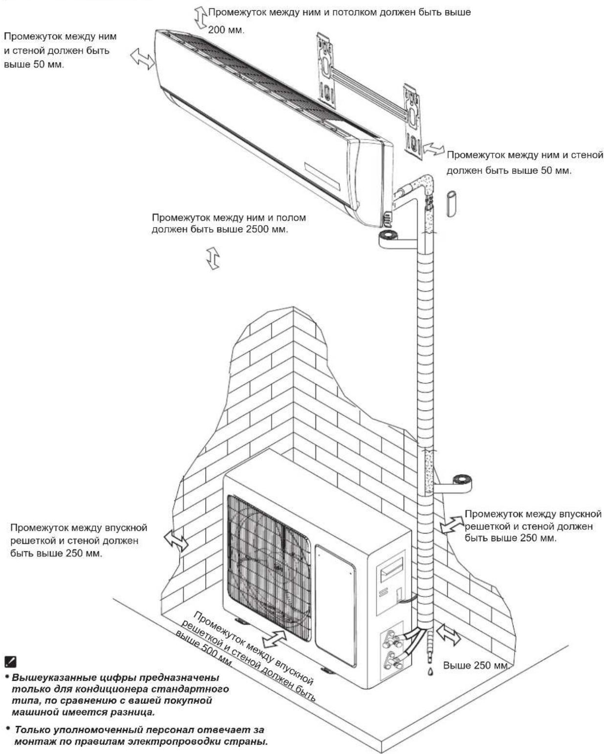
Bb6op mecma ycmaHOeKu
MohmaxHoe Mecmo eHympeHHeu MauuHbI
- IpeEi BbIyckHbIM OTBepCTnEM Bo3Dyxa He CneJeYe IMeTb IIO6oe PpEnrTcTBne, BO3Dyx KOHNIOHOHa MoKET ydaHPO pacnpoctpaHbT NO CEJNO KOMHate.
- MoTaxHoe MeTo DoJxHo rapaHTnpoBaTb yO6Hoe paCNooxKeHne Tpy6bl n OTBepCTn CTeHbl.
- InpaBnAm MoHTaxHOn CXEmbl npOdyKun B npdeIduyue CTpaHnCe, rapaHTnpoBaTb npOMeKytOK MeKdy CTehOu NNOTOLKom BHYtpHeMaUNHBi.
MOHTaXHoe MeCTO DOJIXHO rapaHTnPOBaTb yIO6HOe CHrTne FmNbTPaCNOHON CEKN.
PacctoHne MeKdy BHyTreHHe MaunHO, KOHTpoJIepOM N TeEBN3OpOM, padnoonpneMHNKOM DOJNXHO 6bTb 60nee 1 M.
Bo n36eKaHHe NomExn pnyopecEHTHOIaMnbl Ha BHyTpEHIO MaunHy, Heo6xOJIMO OTdAnrTbcraOT Hero.
Kak MoxHO BOTaJIeHNOT fIyopeCeHTHOJ lambli
Bo n36exhaHHeycnEHHoro Bnycka Bo3dyxa BHytpenHe MaunHbI,pepeBnyckHO peWtKo BHytpenHe MaunHbI He cneDyET nooxntb IIO60 npedmet. - YctaHOBJIeH Na CTHe, rIe MoXHO DOCTaTOHOBbEApKBt Bc6JIOKa.
- YctaHOBHeHaMeTe, He He 6yET yBeInuBaTb Wm DeIcTBn I KOJIe6aHne.
B O tДанeHио nO TnpMbIX coJIHeuHbIX nyuei nIcToHnka HarpeBa. HeIb3a NIOKHTb JERKOBCnPaMeHouCi MATEpHaN IIN TOnOyHoe yCTpoIcTBO Ha Bepxu daHHoro 6noka.
Mecmo ycmahoeku HapyxHou Maunhbl
- MecTo yCTaHOBKn DOJIKNHO 6bITyIO6HbIM N BEHTINRAOHHbIM...
- Henb3y yctAHOBITb B MecTe, rIe JERKO Bo3HnKaTb yTeKY OrHeONaCHOro ra3a.
Heo6xOIMO rapaHTnpoBaT npOMeKyTOK MEkDy HApXHO MaunHO nCTeHO.
PacctoHHe Mekdy BHyTpHeHne MaunHO HApyXHoMaUNHO DoJHXo 6bITb HNKe 5M.Bcnyae do6abneHnOxnaKdaUoero areHTa,MakcImaNbHoe pacctoHHeDOnKHO 6bITb He Bblue 15M.
MecTo yctaHOBKn HapyKHO MaunHb DOJXHO OTdaJIbTbcr O T3acnBaHn nn cepnCTOro ra3a.
Bo n36eKaHHe NOBpeXdEHNHaAMoBOI BoDbl, HeJIb3aYcTaHOBnTb HApyKHyIO MaunHy No CTopoHaM DOpOrn.
-Bo n36eKaHne yBEnuHcHnna 7yMa, cNeDuYyCTaHOBnTb HApUxKHyMoMauHnHy B IpOuHyIO OCHOBy.
CneNyETyCTAHOBITb HApxHyMoMmHnHy BMeTe, rDe BBIXOHOE OTBepCTHe BO3DyXa He IMeET PpenTCTBn.
Bи36eJahHe yctAHOBKn nOД nprrMbIe coJIHeUHbIe lyuN, B npnxOJe nIN c6Oky, nIN BnIMn HcTOOHNa HArpeBa nBeHTInrTOpa. B OTdaneHnn O T IERKOBocnIaNMeHIOUeROCa MaTePnaIa,CnIbHorO MaCInHOrO TymHa, MOKporo INHepOBHORo MeCTa.
CoeINHeHne Tpy6OpPobOa:
a. CoeINHnTe TpybONpOBoD BHyTpeHHeMaunHbI DByMraeyHbIMKnIOaMNI. Oco6o ydeJrB HmMaHne DoNcyTMOMy MOMHTy Cnbl, Yka3aHHOMy B CneIyUoe cxeme, UTO6bl IpeOnTbpaauTaB NOBpeKdHHeu Nn DeΦOpMaucIO TpybONpOBOda, coeINHeHn nn raeK CoeINHnTeHbHO Tpy6bl.
b. Chayana noTgRnBaIte naIbIaMn, NOTOM 3aBnHTntb raeYHbIM KIOyOM.
| Тин | Раимер трубов现代物流 | Моемен син� | ШирINA гаек | Минимальни толочипа |
| 7,8,9,10,12,14,18K | Бokobая.stорona.jждков.Tрубы(Ф6 MM.Iлл дюм 1/4) | 15~20N·m | 17mm | 0.5mm |
| 18K*,21,22,24,25,30K | Бokobая.storopona.jждков.Tрубы(Ф9.53 MM.Iлл дюм 3/8) | 30~35N·m | 22mm | 0.6mm |
| 7,8,9,10,12K | Бokobая.storopona.razobov.Tрубы(Ф9.53 MM.Iлл дюм 3/8) | 30~35N·m | 22mm | 0.6mm |
| 12K*,14K,18K | Бokobая.storopona.razobov.Tрубы(Ф12 MM.Iлл дюм 1/2) | 50~55N·m | 24mm | 0.6mm |
| 18K*,21,22,24,25,30K | Бokobая.storopona.razobov.Tрубы(Ф16 MM.Iлл дюм 5/8) | 60~65N·m | 27mm | 0.6mm |
*Tn KOHdNtioHepa12K* 60jIbe, yem 12K.Tn KOHdNtioHepa18K* 60jIbe, yem 18K.
Onucahue Mohmaka npodykuuu
4. CoeDInHeHne Ka6eJra
BHyTpeneMaunHa
3NeKtpnueckoe coeHHeHne BHyTppeHne MaunHbI 3aKnIOuAetcB TOM, YTO NO MeTOny COeHNHeHn npOBOD HApYKHO MaUNHbI OTDeJIbHO COeHNrTb 3NeKtpnpoBOc 3axmOM NaHeJy npabHeHn.
BHHMaHHe:JnH HeKToOpbIX TINOB, Tpe6yET CHaTb KOpNyc, YTO6bl CoeHNrHb C 3axHMOM BHyTpEHHeMaunHbI.
HapyxHaMaunHa
1).BbIBNHTIe BnHT n ChrTb KOxyx 3JeKTPoPpOBOkIn n3 HapyXHO MaunHbI.CoEINHrTB CnIOBOI npOBOD C 3aXIMOM NaHeN ynpaBLeHnra (KaK NOKa3aHO B HnKeCneDyUOux NyHKtax).
2).Kpenite cniloBoI npoBcB naneJb ynpaBHeHnC NOMOsbIO Ka6eJIbHOr3axmHa.
3).YCTaHOBtTeB BVHTaMn KOxUx 3NeKTpOpOBoDkn B NCXoHHe NOJIOKeHne.
4).Длг.TINOB MaUNHb 24 K n BbIe, MeKdIy NITaHnEM n KOHNIOHepOM CJIeDyET yCTaHOBNTb CTaHApTHbI BIKNUOyATEJIb.
Heo6xOIMO yCTaHOBtB BbIKIOuAIOUe yCTPOIcTBO, KOToPoE MOKe T npABNJbHO BbIKIOUHTb BCE CINOBbie npoBObl.
BHHMaHHe:
PepednnaHb 3aKIM (BHyTpEHn)
BHytpenHmaunHa
Pama
3aKIM KOKyxa 3JIeKTPonpOBOdkn (BHyTpHnnI)
HapyxHaMaunHa
LHpbB DaHHo INCHpyKUIN OCHOBBaIOCTHa CXME BHEIHIRO BIDA CTAHDAPTHORO Tnna.No3OTMy, NO cpaBHeHIO BaUNM NOKyNHBIM KOHNMOHEPOM,BHEUHN BID KOHNLIIOHepa B DaHHo INCHpyKUIN BO3MOKHIO IMeET pa3HNU.
- Heo6xOIMO CneuaIbHO yCTaHOBITb OTJeIbHbIK KOHTyp IITaHnIy IJI KOnIuNIOhepa.MeToD 3JKeKtpOpBOOdkn CMOTpNTe 3JKeKtpUeCKyO CXemy B KOKyXe 3JKeKtpOpBOOdkn.
2.Диametр ka6eJrdoJIkeH COOTBETCTBOBaTb npabNJAM cTaHapTa 3NeKTPoNTaHnA.
3.Поверпге Линию rapaHTnpoBaT npOHye KpeHJIeHne nocHe coeHINHЯ ka6eJЯ.
4.ДЯВlaЖнОЗ30HbHeO6XODmO yCTaHOBnTbпрьBaTeJIbHa 3eMNI.
CTaHdApT Ka6eJra
| Емкость кабел (Вtu/h) | Силовий правор | Силовий правор | ||
| Тун | Hopmanshoe посерчhoe сейесни | Тун | Hopmanshoe посерчhoe сейесни | |
| 7K~12K | H07RN-F | 1.0 mm/1.5X3 | H07RN-F | 1.0 mm X5/1.5 |
| 7 12K*~ K* | 1.0/1.5mm²X3 | H07RN-FH | 060X1-5mm²X4 | |
| 14K~18K | H07RN-F | 1.5mm²X3 | H07RN-F | 1.5mm²X5 |
| 14K*~ K*18 | H05VV-F | 1.5/2.5mm²X3 | H07RN-F | 1.5mm²X4 |
| 21K~30K | H07RN-F | 2.5mm²X3 | H07RN-F | 0.75mm²X4 |
| H07RN-F | 2.5mm²X3 | H07RN-F | 2.5mm²X5 | |
| 21K*~30K* | 2.5mm²X3 | H07RN-FH | 052/5mm²X4 | |
Ппмочанe: K* 03начaET,ЧТОЗКТРОПТАнe ДАнHо мОДeни I3 BHyтpeHero 6noka.
BHHMaHHe:
Tencenb Heo6xOJIMO 6bIb JERKOIOCTyHbIM NocJe yCTAHOBKn DaHHoro annapaTa B cnyuae Heo6xOJMOCTn ero HecoeiHHeHNA. EcIn HeBO3MOXHO, CoeHNHTe annapat C KOMMyTAUHOHON
annapaTpyo n DByMa NOnIOcmN, B TOM YnCne OTdeJeHHe KOHTaKaK MUNHMym 3mm² B DOCTynHom MeCTe daxe nocIe yCTaHOBKn.
Onucahue MOhmaKa npodykuuu
Cxema 3JekTpponpoBokn
FapahmupymeoHaKobuueem cuioo20 npooba u Homep 3axumoe Mexy eHympeHHeu Mauhou u Hapyxho Mauhou.
· Tun 7K^12K^
- Tun14K* 30K~
-Tun 7K 30K~

Длma moJIeN K*, 3neKtpOnnTaHHe coeHHeNo n3 BHyTpEHHero 6Ioka C BbIKNUOHTaTeJIeM. 3TOT rpaФNK TOnbKO dЯ cnpaBKn, ФakTNueckn TepMNHaJ YBJIeTcR peaJIbHbIM.
Onucahue MOhmaKa npodykuuu
MoHTaX HApxKHO MaunHbI
1.YctaHOBnte BbInyckHoe OTBepCTne IN dpEhaxHyTo Tpy6y (TOnbko TnN TeNIOBORo Hacoca).
Korda KOHduuHep pa6oTaET BpeXMe «HaPeBa», HapyxHa MaunHa BbIyckaet KOHdeHcauHNOHyIO BODy.
Tc06bI He MeMaTaB HopMaJIbHOJ K3Hn BaUero Coceda n 3aUuTaB OkpyKaIOUyO cpedy, cIeDyEY UCTaHOBt BByInyCKHoe OTBepCTne I dpeHaXHyTO py6y DNr TeChENKoHDeHCAUHOH BOdy. ToNkO yCTaHOBt DEpaHXHoe OTBepCTne I pe3INHOy Oa6y Dn r NOdoHA BHeUHero 6NoKA, NOTOM CoedHHte DpeHaXHy TOpy6y C OTBepCTmE, KaN oKa3aHO Ha npabom pncyHke.
2.YcTaHOBnTe IN KpeINrHApyKHyO MaunHy.
IpouHO yctAHOBNTe 6oTn raiKn Ha pOBHOM, npOCHOM noJy.
Ecnn Tpe6yETcYcTaHOBnTb Ha cTeHe NnHa KpbIe, Heo6xOJIMO rapaHTnpOBaT npouHoe KpenneHne onOpbl, He cNeDuYeT BO3HnKaTb TpRceHne n3-3a CnIbHoro KoJe6aHn Nn CnIbHoro Betpa.
3.CoeHHeHne Tpy6oPbOBoa HApyXHO MaHnHbI
- ChnIMTe KpbIuKy DByxxOIOBOrO KJIanaHa N TpexxoIOBOrO KJIanaHa.
-
YcTaHOBJIeHHOM My MOMeHTy CINbI CoeINHrTb Tpy6oNpOBoD C DByXXoIOBBIM KJIanaHOM IN TPexxOIOBbIM KJIanaHOM.
-
CoeDInHeHne Ka6en HapyKHO MaunHbI (CMOTpITe npdeBdyuin JnCT)
Bbinyck Bo3dyxa
OCTaTOHbI Bo3dyB OXJaXdaIOSeI cIPKylqun IMeET BnaXHOCTb, MoKeT npINBOITb K BO3NKnHOBeHHIO HeNCpabHOCTe KOMPpeccopa. Iocne CoeINHeHMaJy BHyTpENHe MaIHHO HApJHKoMaIHOO, C NOMOuB BaKyMMHO HAcoca BblNyCKaTb OCTaTOHbI BO3dyX N BNaXHOCTb B OXnKaDaIOSeI cIPKylqun, KaK NOKa3aHO Ha CneDyUoem pncYKe.
BHHaHHe:B cIeX 3aunTbO kpykaoue Cpebl, Hnbl3y nprrMo BbyNcKaTb oxnaJdaouu areHT B aTMocfepy.lar BbyNcKa BO3dyxa CMOTPnTe B cIeDyUoem CTpaHnue.
Onucahue Mohmaka npodykuuu
Kak ounctnbra30bbl Tpy6o npoBOd:
(1).BbInHTe BnHT n CHIMnTe KpbIshky DByxxoOBOrO KnaHa n TpexxOoBOrO KnaHa.
(2).BbIBHNTe BHT N CHIMNTE KpbIky peMOHTHOKnanaHa.
(3). CoeHHnte pyKaB BaKyyMHO HAcOcA C peMOHTbIM KJIaIHaHOM.
(4). Nycnte Bakyymhbln hacoc n pa6oTaB okono 10~15 MNH., BNIOb DO TORO, KOrda Bakyym doCTur 10 MM. pTyTHoro cToI6a.
(5).Пи pa6oTe BakyymHoro HAcoca,ЗakpoIe KhoIky Hn3KOrO DaBJIeHnB MaHnФОЛьde BaKyymHoro Hacoca.ПOTOM OCTaHOBIne BakyymHbI HAcoc.
(6). OTKpoTe DByxxoOBoK knaan Ha 1/4, uepe3 10 cek. chOba 3akpbIt b erO.C nOMoUbIOMbIbHOrO pactbopa nn 3JNeKTPOHHoro yKa3aTeJIyTeuKn npOBepTb repMeTuHOCt b coEduHeHn.
(7).BpaaaIte 2 n 3 klaanahHoro pbyara dna noJIHOCTbIO 3akpbita klaanaHa. OTKJIIOUHTe r6kni shaHr BakyumHoro Hacoca.
(8). 3 ameHTe n 3aBHTnTe KpbIky KJIanaHa.
Hisense
- Contents
- Safety instructions
- Preparation before use
- Note
- Preset
- Safeguarding the environment
- SCRAPPING OF APPLIANCE
- Safety precautions
- Identification of parts
- Display introduction
- Maintenance
- Front panel maintenance
- Air filter maintenance
- Protection
- Operating condition
- Noise pollution
- Features of protector
- Features of HEATING mode
- Preheat
- Defrost
- Troubleshooting
- Installation instructions
- Select the installation location
- Location for Installing Indoor Unit
- Location for Installing Outdoor Unit
- Indoor unit installation
- Installing the Mounting Plate
- Drill a Hole for Piping
- Indoor Unit Piping Installation
- Piping Connection:
- Connecting of the Cable
- - Indoor Unit
- - Outdoor Unit
- Caution:
- Attention:
- Wiring diagram
- Outdoor unit installation
- Air purging
- How to Purge Air Tubes:
- Hisense
- Manutenção do painei frontal
- Installatie-instructions
- Bedrangdisdiagram
- Pollution sonore
- ycnoBne pa6oTbI
- ocobehnoctbpexima HEATING(HARPEBA)
- Iodoapee
- Ommaeahue
- PeweHue HeucnpaBocmeu
- OnucHue MoHmka npOdykuu
- MoHTaxHna cxema npodykun
- Bb6op mecma ycmaHOeKu
- MohmaxHoe Mecmo eHympeHHeu MauuHbI
- Mecmo ycmahoeku HapyxHou Maunhbl
- CoeINHeHne Tpy6OpPobOa:
- Onucahue Mohmaka npodykuuu
- CoeDInHeHne Ka6eJra
- BHyTpeneMaunHa
- HapyxHaMaunHa
- BHHMaHHe:
- Cxema 3JekTpponpoBokn
- MoHTaX HApxKHO MaunHbI
- Bbinyck Bo3dyxa
Brand : HISENSE
Model : AST12UW4RXXQA
Category : Air Conditioning