EXI09HL1W - Air-conditioner ELECTROLUX - Free user manual and instructions
Find the device manual for free EXI09HL1W ELECTROLUX in PDF.
User questions about EXI09HL1W ELECTROLUX
0 question about this device. Answer the ones you know or ask your own.
Ask a new question about this device
Download the instructions for your Air-conditioner in PDF format for free! Find your manual EXI09HL1W - ELECTROLUX and take your electronic device back in hand. On this page are published all the documents necessary for the use of your device. EXI09HL1W by ELECTROLUX.
USER MANUAL EXI09HL1W ELECTROLUX
INSTALLATION MANUAL 1
MANUEL D'INSTALLATION 23
EIXPIIO EKATAZTAH2 45
MANUALE PER 67
L'INSTALLAZIONE
MANUAL DE INSTALLACION 89
Congratulations
Congratulations and thank you for choosing Electrolux split-type air conditioner. We are sure you will find your new air conditioner a pleasure to use.
Before you use the air conditioner, we recommend that you read through the entire user manual, which provides the description of the air conditioner and its functions.
To avoid the risks that are always present when you use an electrical appliance, it is important that the air conditioner is installed correctly and that you read the safety instructions carefully to avoid misuse and hazards.
We recommend that you keep this instruction booklet for future reference and pass it on to any future owners.
After unpacking the air conditioner please check it is not damaged. If in doubt, do not use the air conditioner but contact your local authorised service centre.

environmental tip
Information on disposal for users
- Most of the packing materials are recyclable. Please dispose of those materials through your local recycling depot or by placing them in appropriate collection containers.
If you wish to discard this air conditioner, please contact your local authorities and ask for the correct method of disposal.
Conditions of use
This appliance is intended to be used in household and similar applications such as:
Staff kitchen areas in shops, offices and other working environments.
- Farm houses.
- By clients in hotels, motels, and other residential type environments.
Bed and breakfast type environments.
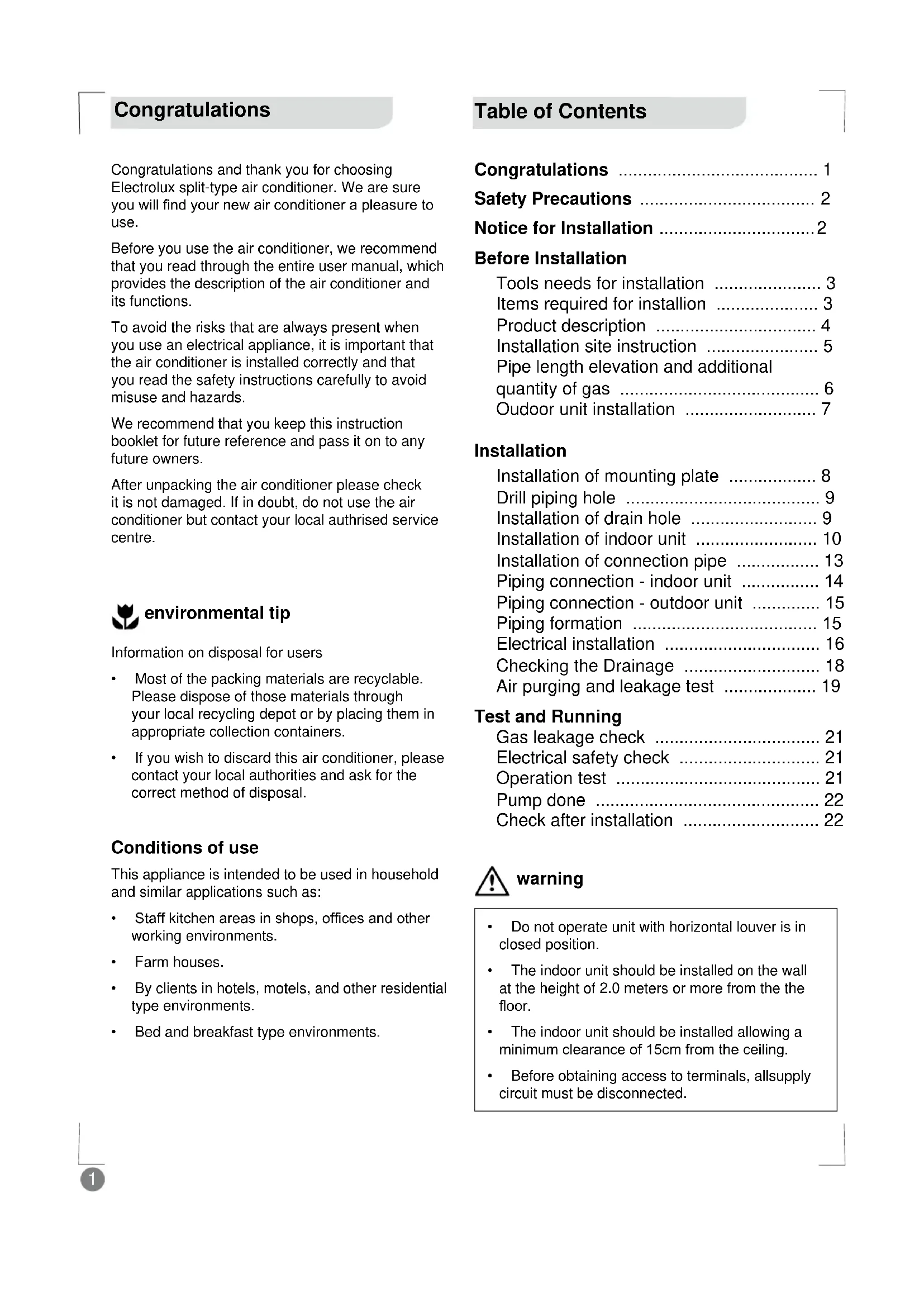
Table of Contents
Congratulations 1
Safety Precautions 2
Notice for Installation 2
Before Installation
Tools needs for installation 3
Items required for installment 3
Product description 4
Installation site instruction 5
Pipe length elevation and additional quantity of gas 6
Outdoor unit installation 7
Installation
Installation of mounting plate 8
Drill piping hole 9
Installation of drain hole 9
Installation of indoor unit 10
Installation of connection pipe 13
Piping connection - indoor unit 14
Piping connection - outdoor unit 15
Piping formation 15
Electrical installation 16
Checking the Drainage 18
Air purging and leakage test 19
Test and Running
Gas leakage check 21
Electrical safety check 21
Operation test 21
Pump done 22
Check after installation 22

warning
- Do not operate unit with horizontal louver is in closed position.
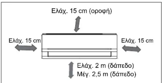
- The indoor unit should be installed on the wall at the height of 2.0 meters or more from the the floor.
- The indoor unit should be installed allowing a minimum clearance of 15cm from the ceiling.
Before obtaining access to terminals, allsupply circuit must be disconnected.
Safety precautions
Please ready this installation manual and the user manual before installation and carefully store in a handy place for later reference.
Inside this manual you will find many helpful hints on how to use and maintain your air conditioner properly.
Electrical work must be installed by a licensed electrician. Be sure to use the correct rating of the power plug and main circuit for the model to be installed.
Incorrect installation due to ignoring this instruction will cause harm or damage, and the seriousness is classified by the following indications.
Meanings of symbols used in this manual are shown below:

warning
This symbol indicates information concerning your personal safety.

caution
This indicates information concerning your personal safety and how to avoid damaging the appliance.

tips and information
This symbol indicates tips and information about use of the appliance.

environmental tip
This symbol indicates tips and information about economical and ecological use of the appliance.

This symbol indicates never to do this.

Always do this.
Notice for Installation

caution
1 The unit must only be installed by a qualified refrigeration mechanic and electrical work carried out by a qualified electrician according to local or government regulations and in compliance with this manual.
2 Before installation, please contact a qualified air conditioner installer. Otherwise, the malfunction may not be solved due to faulty installation.
3 If the power cord is damaged, replacement work shall be performed by authorised personnel only.
4 The appliance must be positioned so that the plug is accessible.
5 The temperature of refrigerant circuit will be high, please keep the interconnection cable away from the copper tube.
6 This appliance is not intended for use by persons (including children) with reduced physical, sensory or mental capabilities, or lack of experience and knowledge, unless they have been given supervision or instruction concerning use of the appliance by a person responsible for their safety.
Young children should be supervised to ensure that they do not play with the air conditioner.
7 If the unit is to be moved to another location or disposed of, only a suitably qualified person is permitted to undertake such work.
8 Take care not to catch fingers on the fan blade when adjusting vertical louvers.
9 This air conditioner uses R410A refrigerant (Confirm before installation).
Tools Needs for Installation
1 Level gauge
2 Screw driver
3 Electric drill
4 Hole core drill ( 55mm / 70mm)
5 Flaring tool set
6 Specified torque wrenches
7 Spanner (half union)
8 A glass of water
9 Hexagonal wrench (4mm)
10 Gas-leak detector
11 Vacuum pump
12 Gauge manifold
13 Users manual
14 Thermometer
15 Multimeter
16 Pipe cutter
17 Measuring tape
Items Required for Installation
| Number | Name of | Accessories |
| 1 | Indoor unit mounting plate 1 | |
| 2 | Clip anchor Not supplied | |
| 3 | Self-tapping screw ST4 x 25 5 | |
| 4 | Remote control 1 | |
| 5 | Remote control holder 1 | |
| 6 | Screw for remote holder | 2 |
| 7 | Battery (AAA 1.5V) | 2 |
| 8 | Insulation material | Not supplied |
| 9 | Connection piping assembly (refer to page 6) | Varies by country |
| 10 | Insulation hose for refrigerant piping | Not supplied |
| 11 | Wall clamp | Not supplied |
| 12 | Drain hose | Not supplied |
| 13 | Connection power cable | Not supplied |
| 14 | Drain connector (Heat Pump model only, page 7) | 1 |
| 15 | Drain plug (Heat Pump model with capacity of over 4500W) | 3 |
| 16 | Thermal insulating pipe for extending drain hose | 1 |
| 17 | Flare nut (for suction pipe) | 1 |
Note: Other necessary parts for the installation, besides the above mentioned, must be provided by the customer/installer.
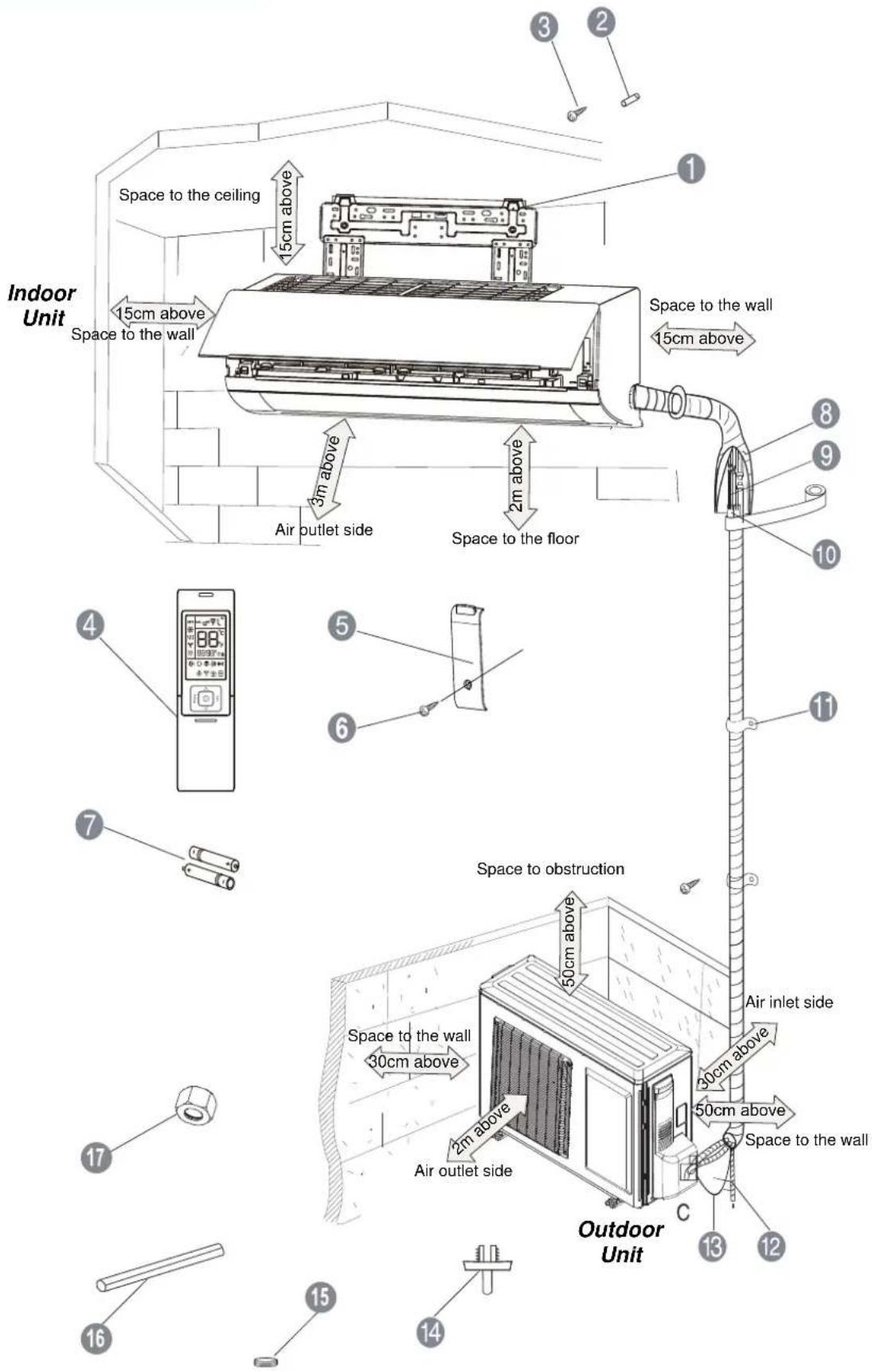
Product Description
Installation Site Instruction
A proper installation site is vital for correct and efficient operation of the unit.
Avoid the following sites where:
- strong heat sources, vapour, flammable gas or volatile liquids are emitted.
- high-frequency electro-magnetic waves are generated by radio equipment, welders or medical equipment.
- salt-laden air prevails (such as close to coastal areas).
- the air is contaminated with industrial vapours and oils.
- the air contains sulphurous gas such as in hot spring zones.
corrosion or poor air quality exists.
Indoor Unit
1 The air inlet and outlet should be away from the obstructions. Ensure the air can be blown through the whole room.
2 Select a site where the condensing water can be easily drained out, and where it is easily connected for the outdoor unit.
3 Select a place where it is out of reach of children.
4 Select the place where the wall is strong enough to withstand the full weight and vibration of the unit.
5 Be sure to leave enough space to allow access for routine maintenance.
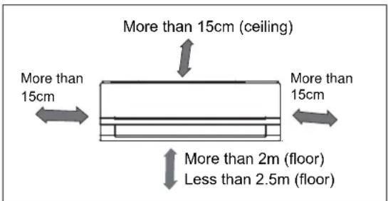
For optimum performance, the indoor unit should be installed on the wall at a height 2 meters or more above the floor but less than 2.5 meters from the floor.
6 Make sure that the indoor unit is installed in accordance with installation dimension as below:
7 Select place about 1m or more away from a TV set or any other electric appliance.
8 Select a place where the filter can be easily taken out.
9 Do not use the unit in the laundry or by swimming pool etc.
10 A minimum pipe run of 3 meters is required to minimize vibration and noise.
11 Use a stud finder to locate studs to prevent unnecessary damage to the wall.
12 Any variations in pipe length will/ may require adjustment to refrigerant charge.
13 Do not install near a door way.
Outdoor Unit
1 Select a site where noise and outflow air emitted by unit will not annoy neighbors.
2 Select a site where there is sufficient ventilation.
3 Select a site where there is no obstruction blocking the inlet and outlet.
4 The site should be able to withstand the full weight and vibration of the unit.
5 Select a dry place, but do not expose the unit to direct sunlight or strong wind.
6 Make sure that the outdoor unit is installed in accordance with the installation instructions, and is convenient for maintenance and repair.
7 Select a place where it is out of reach of children and far from animals or plants.
8 Select a place where it is out of reach of children and far from animals or plants.
9 Select a place where the unit keeps the horizontal and aligned position.
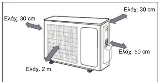
10 Select at a place that respects the minimum distances around the outdoor unit as below:
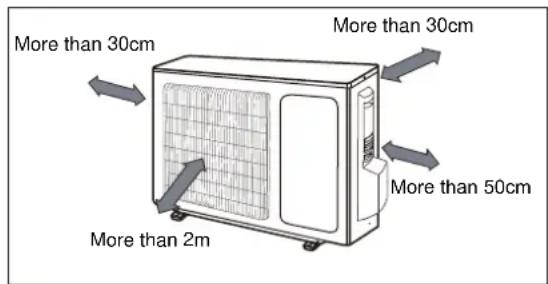
Rooftop Installation
1 If the outdoor unit is installed on a roof structure, be sure to level the unit.
2 Ens ure the roof structure and anchoring method are adequate for the unit location.
3 If the outdoor unit is installed on roof structures or external walls, this may result in excessive noise and vibration, and may also be classed as non-serviceable installation.
Pipe Length Elevation and Additional Quantity of Gas
| Model Number | Suction Pipe Diameter | Discharge Pipe Diameter | Standard Length (m) | Maximum Length (m) A | Maximum Height (m) B | Additional Refrigerant (g/m) |
| EXI09HL1W-A1 | Ø6.35 mm (1/4") | Ø9.52 mm (3/8") | 5 | 15 | 10 | 15 |
| EXI12HL1W-A1 | Ø6.35 mm (1/4") | Ø9.52 mm (3/8") | 5 | 20 | 10 | 15 |
| EXI09HL1W-A2 | Ø6.35 mm (1/4") | Ø12.7 mm (1/2") | 7.5 | 15 | 10 | 20 |
| EXI12HL1W-A2 | Ø6.35 mm (1/4") | 12.7 mm (1/2") 7.5 | 20 | 10 | 20 | |
| EXI18HL1W-A2 | Ø6.35 mm (1/4") | Ø15.88 mm (5/8") | 7.5 | 25 | 10 | 50 |

caution
- The outdoor unit is charged with the refrigerant for standard pipe length.
- When the connecting pipe length is longer than standard length, additional refrigerant should be added into the unit according the above table through the service port on 3-way service valve on the outdoor unit.
- Please maintain the shortest distance (3 to 5 meters) and shortest misalignment possible between the indoor and outdoor units.
The maximum allowance length and height is based on reliability. Exceeding the maximum may cause poor performance or malfunction.
- When the level difference between indoor and outdoor units is greater than maximum height, or when the outdoor unit is installed above the indoor unit, oil trap should be installed every 5-7 meters.
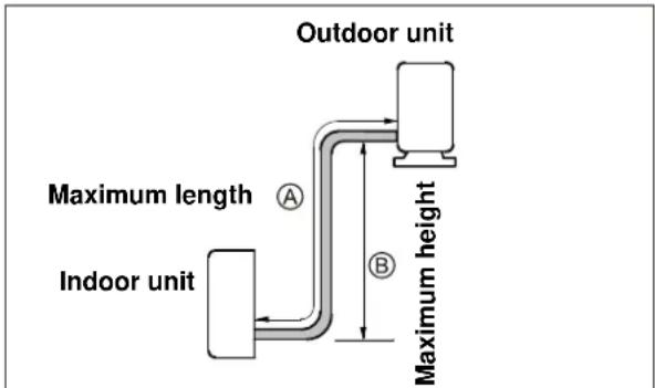
Piping length under 5m
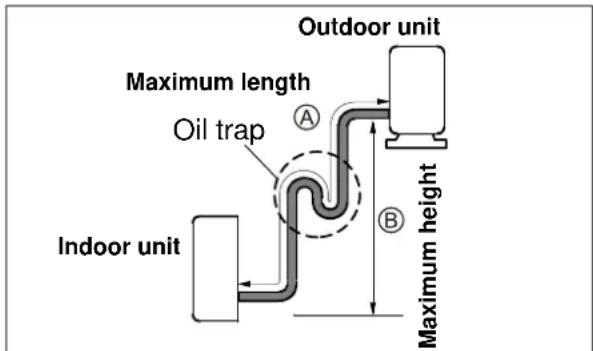
Piping length 5m or more
Outdoor Unit Installation
Step 1: Securing of Outdoor Unit
- Anchor the outdoor unit by fixing the 4 holes existent in its based with 4 bolts and nuts of 10mm tightly (not included).
Place the outdoor unit over a horizontal concrete or rigid surface (never directly over grass or land).
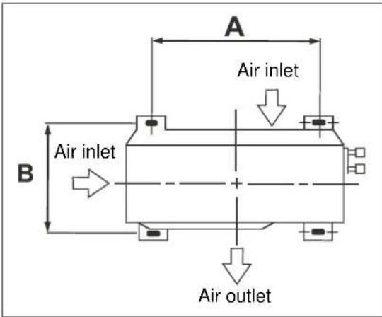
| Outdoor Unit Dimension mm(WxDxH) | Dimension “A” (mm) | Dimension “B” (mm) |
| 776 x 320 x 540 | 510 286 | |
| 848 x 320 x 592 | 540 286 | |
| 899 x 378 x 596 | 550 343 | |
| 955 x 396 x 700 | 560 368 |
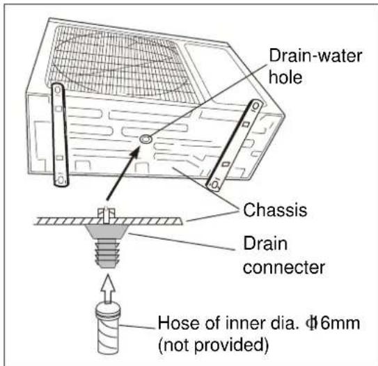
Step 2: Outdoor Condensate Drainage (only for heat pump model)
During heating operation, the condensate and defrosting water should be drained out reliably through the drain hose.
- Install the outdoor drain connector in the drain-water hole on the chassis of outdoor unit, and attach the drain hose to the connector so that the waste water formed in the outdoor unit can be drained out.
- The drain-water hole must be plugged. Whether to plug other holes will be determined by the installer according to actual conditions.
In case of a drain hose, the unit must be installed on a base more than 3cm height.

caution
If a suspended installation is needed, the installation bracket must allow the fixationaccording to dimensions on the figure above.
- The wall where the unit will be installed must be of solid brick, concrete or provided with other reinforcement ways to fix the bracket. The fixation of the bracket to the wall and the bracket to the air conditioner must be firm, steady and leveled.
Installation
Step 1: Installation of Mounting Plate
1 Fit the mounting plate horizontally on the wall with five or more self-tapping screws (type ST4x25, item 3 on page 3).
2 Be sure that the mounting plate has been fixed firmly enough to withstand about 60kg . Meanwhile, the weight should be evenly shared by every screw.
3 If the wall is made of brick, concrete or the like, drill five (5) or six (6) holes of 5mm diameter in the wall. Insert clip anchor (item 2 on page 3) for appropriate mounting screws.
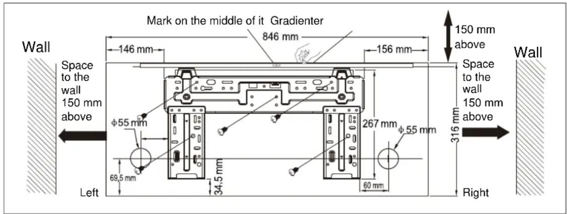
4 The water tray's outlet for the indoor unit is two-way drainage design. During installation, the indoor unit should slightly slant to water tray's outlet for smooth drainage of condenser water.
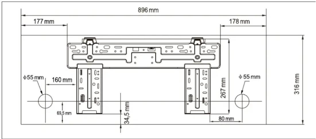
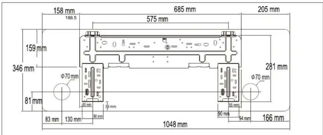
Fit the mounting plate and drill holes in the wall according to the wall structure and corresponding mounting points on the mounting plate. (dimensions are in mm unless otherwise stated)
| Model Number | Indoor Unit Dimension mm (WxDxH) | Mounting Plate Type |
| EXI09HL1W-A1 | 844 x 205 x 316 | A |
| EXI12HL1W-A1 | 896 x 205 x 316 | B |
| EXI09HL1W-A2 | 896 x 205 x 316 | B |
| EXI12HL1W-A2 | 896 x 205 x 316 | B |
| EXI18HL1W-A2 | 1048 x 234 x 346 | C |
Mounting Plate Type A
Mounting Plate Type B
Step 2: Drill Piping Hole
1 Determine hole positions according to the diagram. Drill one (1) hole ( 55 or 70~mm in the wall at a slight downward slant to the outdoor side.
| Piping hole | Model |
| Φ55 mm | Cooling capacity <4500W |
| Φ70 mm | Cooling capacity >4500W |
2 The inclination must be between 5 - 10mm in order to ensure a good drain of condensed water generated by the indoor unit.
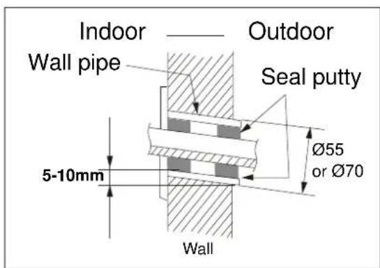
3 Insert the wall pipe into the hole to prevent and wiring from being damaged when passing through the whole.
4 Always use a wall hole conduit when drilling metal grids, metal plates or the like.
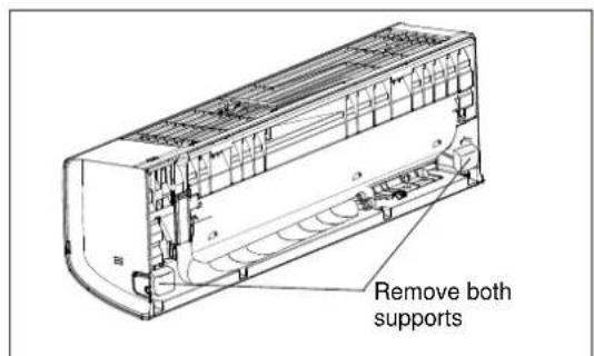
5 For cooling capacity over 4500W models, remove and dispose the two polystyrene lateral rear supports from the indoor unit before the installation.
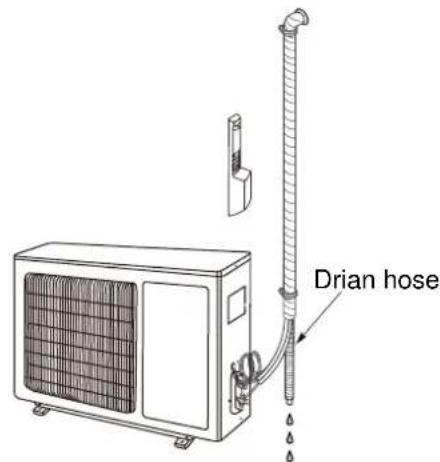
Step 3: Installation of Drain Hose
1 Connect the drain hose to the outlet pipe of the indoor unit. Bind the joint with vinyl tape.
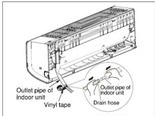
2 Put the drain hose into insulating pipe.
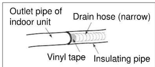
3 Wrap the insulating pipe with wide vinyl tape to prevent the shift of insulating pipe. Slant the drain hose downward slightly for smooth drainage of condensing water.
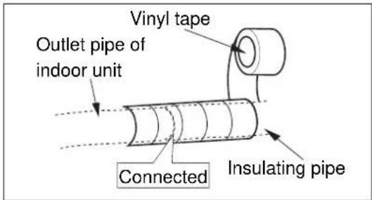

caution
1 The insulating tube should be connected reliably with the sleeve outside the outlet pipe.
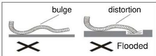
2 The drain hose should be slanted downward slightly, without distortion, bulge or fluctuation.
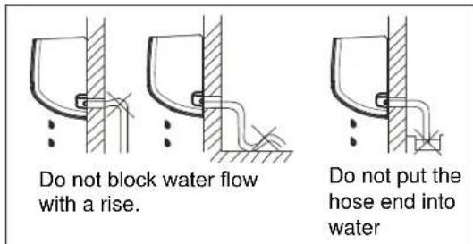
3 Do not put the outlet in the water.
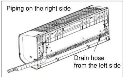
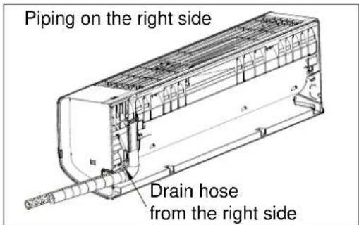
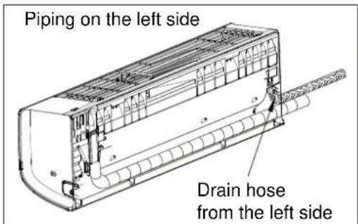
Step 4: Installation of Indoor Unit
The piping can be output from right, rear right, left or rear left.
1 When routing the piping and wiring from the left or right side of indoor unit, cut off the tailings from the chassis when necessary (see figure below).
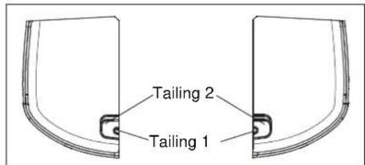
Cut off the tailings 1 when routing the wiring only.
Cut off the tailings 1 and tailings 2 when routing both the wiring and piping.
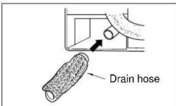
2 The drain hose can be connected at two different positions. Use the most convenient position and, if necessary, exchange the position of drain cap and drain hose.
- The drain hose is connected at the rear left side of the indoor unit when you receive the product.
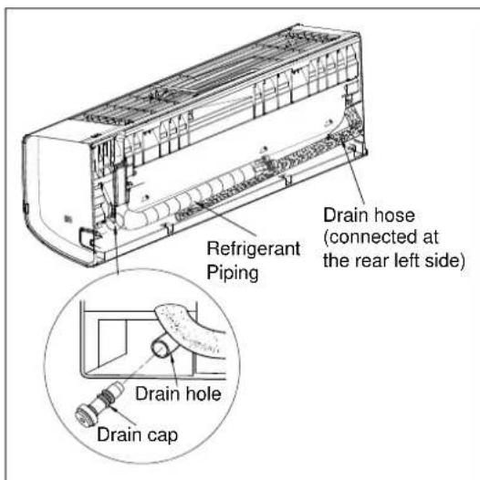
- Follow the instruction as below for exchanging the position of drain cap and drain hose in case from left side to right.
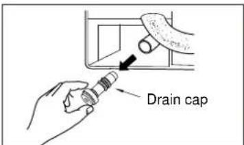
(a) Pull out the drain cap at the rear right of the indoor unit.
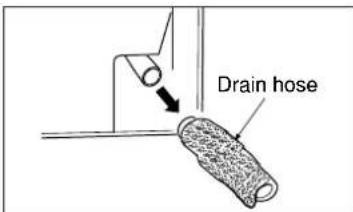
(b) Pull out the drain hose at the rear left of the indoor unit.
(c) Put the drain cap into the drain hole at the rear left of the indoor unit.
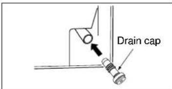
(d) Insert the drain hose into the drain hole at the rear right of the indoor unit.
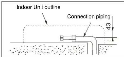
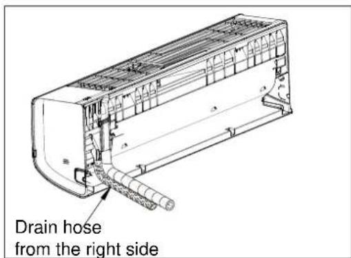
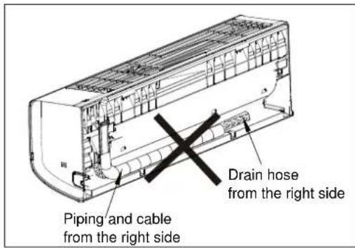
3 Pipe arrangement
- Arrange the pipe in the most convenient direction and position.
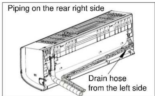
Piping on the rear right side
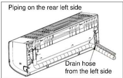
- Do not route both refrigerant piping and drain hose from the right side to the left side to prevent big gap between the indoor unit and the wall.
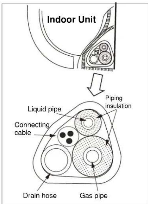
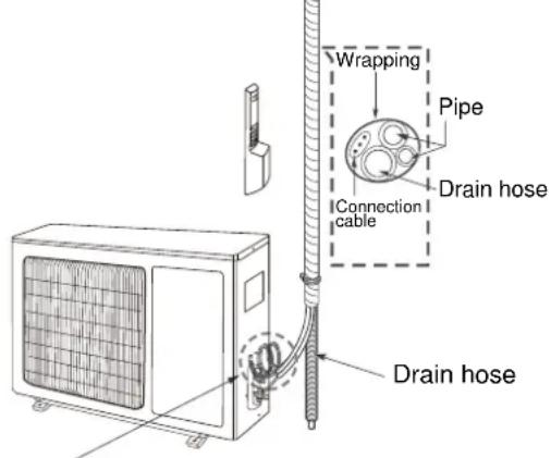
4 Take out the piping from body case, wrap the piping, power cords, drain hose with the tape and then make them pass through the piping hose.
Do not put any object in the drain pan located in the rear of the indoor unit, as the condensed water is gathered there and piped out of the room.

caution
- Connect the indoor unit first, then the outdoor unit.
-
Do not plug the cable to the indoor unit. That must be done later.
-
Turn lightly the cable to make the connection easier later.
- Be careful not to let the drain hose become slack.
- Heat insulate the connecting pipe.
- Be sure that the drain hose is located at the lowest side of the puddle. Locating at the upper side can cause drain pan to overflow inside unit.
- Never cross connect or interwind the power wire with any other wiring.
- Do not allow the piping to be exposed out from the back of the indoor unit.
If part of the drain hose is positioned inside the room, wrap it with insulating materials so as to prevent condensed water from dropping.
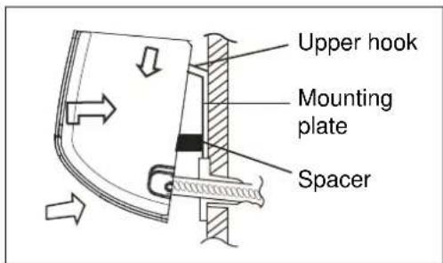
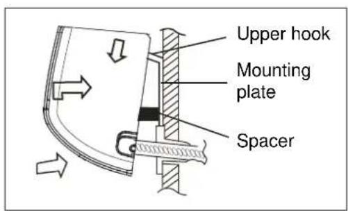
5 Hang the mounting slots of the indoor unit on the upper hooks of the mounting plate and check if it is firm enough.
To ease the piping installation, put a spacer between the indoor unit and the wall.
Remove the spacer once finished.
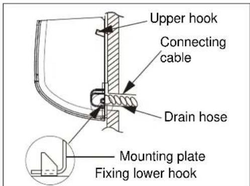
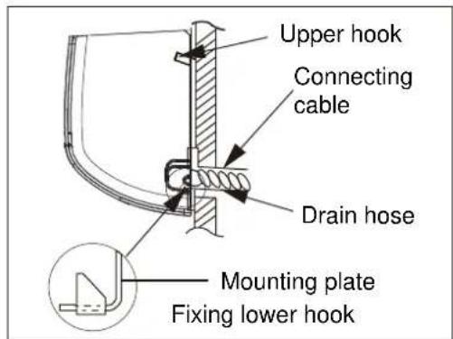
6 Press the lower left and right sides of the unit against the mounting plate until the lower hooks engage into their slots.
Ensure the unit is firmly fitted.
7 The installation site should be 2 meters or more above the floor.
Step 5: Installation of Connection Pipe
Refrigerant pipe connection
1 Flaring work
Main cause for refrigerant leakage is due to defects in the flaring work. Carry out correct flaring work using the following procedure:
A: Cut the pipes and the cable.
- Use the piping kit accessory (if applicable) or pipes purchased locally.
Measure the distance between the indoor and the outdoor unit. - Cut the pipes a little longer than the measured distance.
Cut the cable 1.5m longer than the pipe length.
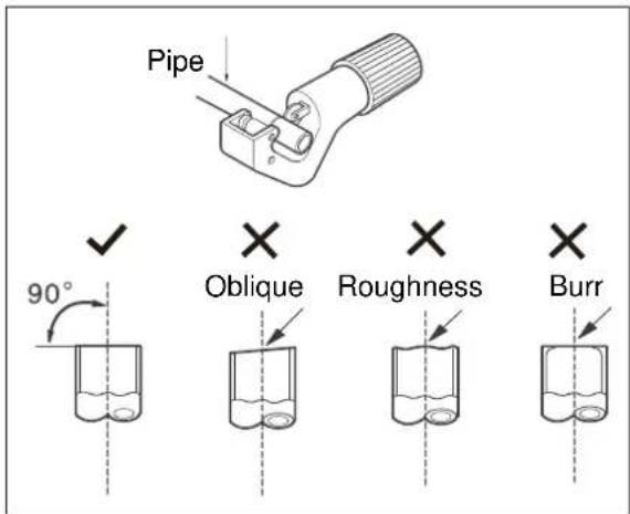
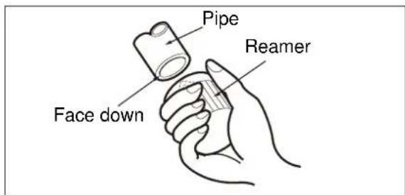
B: Burr removal
- Completely remove all burrs from the cut cross section of pipe/tube.
- Face the end of the copper pipe/tube in a downward direction as you remove burrs in order to avoid burrs dropping into the tubing.
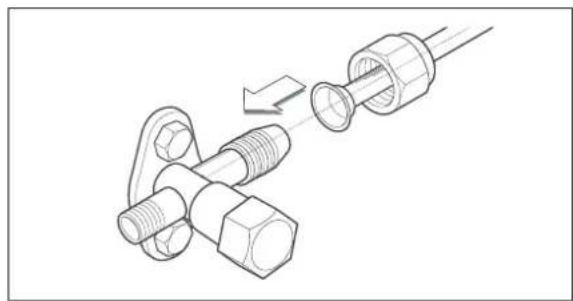
C: Putting flare nut on
- Remove flare nuts attached to indoor and outdoor unit, then put them on pipe/tube having completed burr removal.
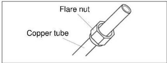
caution
It is not possible to put them on after flaring work.
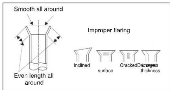
D: Flaring work.
- Carry out flaring work using flaring tool as shown below.
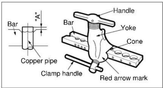
- Firmly hold copper pipe in a die according to the dimension shown in the table below.
| Outer diam. (mm) | A (mm) | |
| Max. | Min. | |
| Φ 6.35 (1/4") 1.3 0.7 | ||
| Φ 9.52 (3/8") 1.6 1.0 | ||
| Φ 12.70 (1/2") 1.8 1.0 | ||
| Φ 15.88 (5/8") 2.4 2.2 | ||
E: Check
- Compare the flare work with the adjacent diagram.
If the pipe has any defect, cut off the enlarged section and redo the work.
Make an independent covering for each pipe with the appropriate tubular isolation.
Step 6: Piping Connection - Indoor Unit
A: Connecting the indoor unit tubing to the connection piping:
- Align the centers of the pipes and sufficiently tighten the flare nut with your hands first.
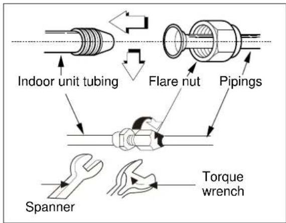
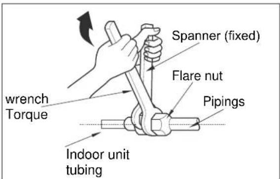
- Then tighten the flare nut with spanner and torque wrench by referring the following:
| Outer diam. (mm) | Torque (N.m) | Additional Torque (N.m) |
| Φ 6.35 (1/4") | 15.7 (1.6kg.m) | 19.6 (2.0kg.m) |
| Φ 9.52 (3/8") | 29.4 (3.0kg.m) | 34.3 (3.5kg.m) |
| Φ 12.70 (1/2") | 49.0 (5.0kg.m) | 53.9 (5.5kg.m) |
| Φ 15.88 (5/8") | 73.6 (7.5kg.m) | 78.6 (8.0kg.m) |

caution
Excessive torque can break the nut depending on installation conditions.
B: Wrap the insulation material around the connecting portion:
- Cover the indoor unit pipe and the connection pipe with the heat insulation material. Bind them together with vinyl tape so that there is no gap.
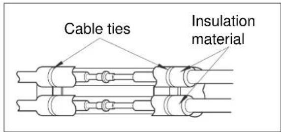
- Ensure to Isolate separately the suction pipe from the liquid pipe.
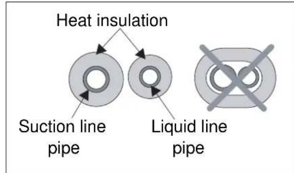
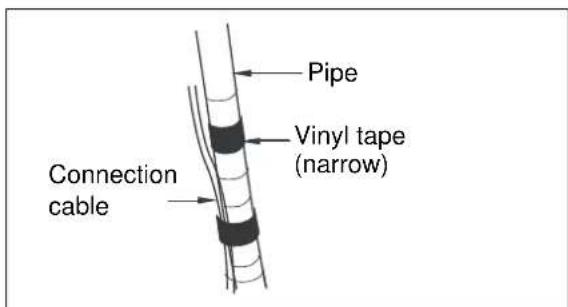
- Wrap the insulated pipes with vinyl tape in the rear section for pipe housing. Fasten the power cable to the pipes with vinyl tape.
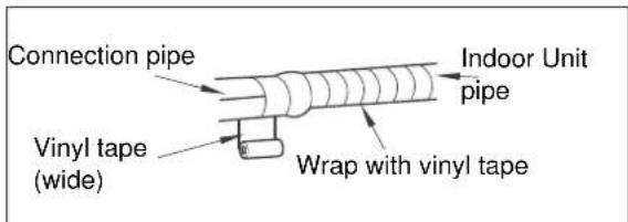
- Wrap the piping, drain hose and power cable tightly with vinyl tape so that they can fit into the rear piping housing section.
C: Positioning the indoor unit:
- Remove the spacer.
- Hook the indoor unit onto the upper portion of the mounting plate (Engage the hooks of the mounting plate into the openings at the rear top of the indoor unit).
Ensure that the hooks are properly seated on the mounting plate by moving the indoor unit in all directions.
- Press the lower left and right sides of the unit against the mounting plate until the hooks engage into their slots (clicking sound).
Step 7: Piping Connection - Outdoor Unit
A: Align the centers of the pipes and sufficiently tighten the flare nut with your hands.
B: Then, tighten the flare nut with torque wrench until the wrench clicks.
Make sure to follow the torque table value as below:
| Outer diam. (mm) | Torque (N.m) | Additional Torque (N.m) |
| Φ 6.35 (1/4") | 15.7 (1.6kg.m) | 19.6 (2.0kg.m) |
| Φ 9.52 (3/8") | 29.4 (3.0kg.m) | 34.3 (3.5kg.m) |
| Φ 12.70 (1/2") | 49.0 (5.0kg.m) | 53.9 (5.5kg.m) |
| Φ 15.88 (5/8") | 73.6 (7.5kg.m) | 78.6 (8.0kg.m) |
Step 8: Piping Formation
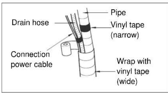
A: Form the piping by wrapping the connecting portion of the indoor unit with insulation material and secure it with narrow vinyl tape and wide vinyl tape.
If you want to connect an additional drain hose, the end of the drain hose outlet should be routed above the ground. Secure the drain hose appropriately.
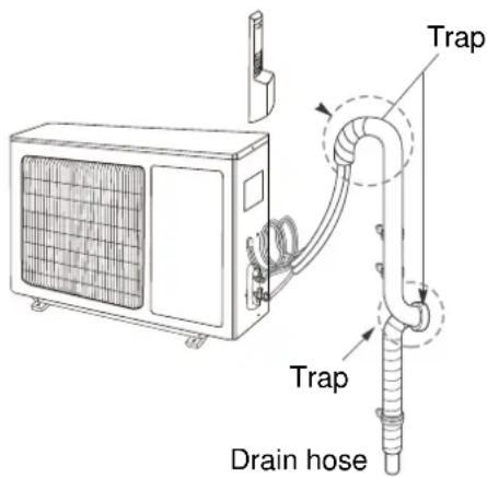
B. In cases where the outdoor unit is installed below the indoor unit level:
- Wrap the piping, drain hose and connecting cable from the down to up.
- Secure the wrapped piping along the exterior wall using saddle or equivalent.
Seal small openings around piping with a gum type sealer.
Trap is required to prevent water from entering into electrical parts.
C. In cases where the outdoor unit is installed above the indoor unit level:
- Wrap the piping and connecting cable from the down to up.
- Form a trap to prevent water from entering the room.
- Secure the wrapped piping along the exterior wall using saddle or equivalent.
Seal small openings around piping with a gum type sealer
Step 9: Electrical Installation
Safety Precautions
Electrical safety rules before starting the installation:
1 A dedicated power supply circuit and breaker should be provided for the products which are not supplied with a service cord and plug in accordance with local electrical safety regulations.
2 The circuit breaker must have the functions of magnetic tripping and heat tripping to prevent short circuit and overload.
3 The appliance shall be installed in accordance with national wiring regulations.
4 A circuit breaker with proper capacity must be installed according to the table below.
| Cooling Capacity (BTU) | Circuit Breaker | Power Cord Gauge | Connecting Cable Gauge | Fuse Type |
| 5000 10A | ≥1.0mm² | ≥1.0mm² | 3.15A | |
| 9000 10A | ≥1.0mm² | ≥1.0mm² | 3.15A | |
| 12000 16A | ≥1.0mm² | ≥1.0mm² | 3.15A | |
| 18000 25A | ≥2.5mm² | ≥2.5mm² | 3.15A | |
5 In case of problems in power supply, the air conditioner must not be installed before the customer fixes the problem.
6 Be sure the power supply matches the air conditioner.
7 Ensure the live wire, neutral wire and earth wire in the power socket are properly connected.
8 Inadequate or incorrect electrical connections may cause electric shock, fire or some electrical parts to malfunction.
9 Before performing any electrical work, turn off the main power to the system.
Earthing Requirements
1 Air conditioner is type I electric appliance. The unit must be reliably earthed and connected to the special earth device by the qualified electrician.
2 The yellow-green wire in air conditioner is the earthing wire which can not be used for other purposes. Improper earthing may cause electric shock.
3 The earth resistance should accord to the national wiring regulation.
4 The user's power must have reliable earthing terminal. Do not connect the earthing wire with the following:
Water pipe
Gas pipe
- Contamination pipe
Installation of Indoor Electric Wires
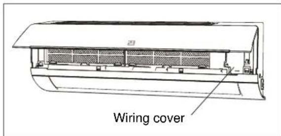
1 Open the front panel and remove the wiring cover by loosening the screw.
2 Route the power connection cable and signal control wire (for heap pump model only) from back of the indoor unit and pull it toward the front through the wiring hole for connection.
3 Connect and screw the wires onto the terminal block as identified by their colors.
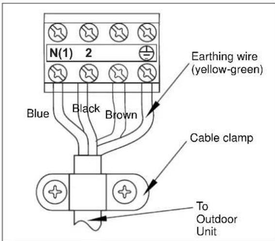
4 Wrap wires that are not connected with insulating tape so that they do not touch any electrical or metal parts.
5 Secure the wires firmly with the cable clamp.
6 Put the wiring cover back and screw it.
7 Reinstall the front panel.

caution
All wires between indoor and outdoor units must be connected by a qualified electric contractor.
If the length of the power cord is not enough, please contact your supplier for new power cord. Lengthen the power cord by yourself is not allowed.
After tightening the screws, pull the wire slightly to confirm whether it's firm or not.
- Do not connect two power cables together to supply power to the air conditioner.
- Do not extend the power cable conductor by cutting.
Installation of Outdoor Electric Wires
1 Remove the handle on the right side plate of outdoor unit by loosening the screw.
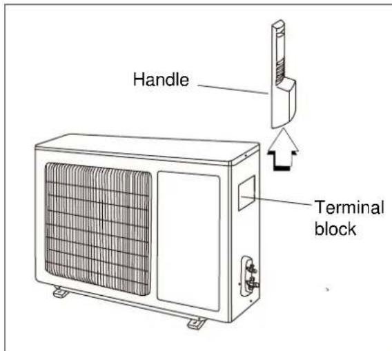
2 Take off wire cable clamp. Connect and screw the power connection cable onto the terminal block following corresponding identification numbers and colors on the terminal blocks of indoor and outdoor units.
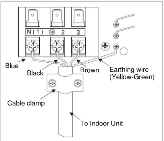
3 To prevent water from entering, make a trap ("U") in the connection wires (see page 16).
4 Wrap wires that are not connected with insulating tape so that they do not touch any electrical or metal parts.
5 Fix the power connection wires with wire clamps.
6 Reinstall the handle.

caution
After confirming the above conditions, prepare the wiring as follows:
- The screws which fasten the wiring to the terminal block may come loose from vibrations during transportation. Check and make sure all screws are well fixed. Otherwise, it could cause burn-out of the wires.
- Be sure the circuit capacity is sufficient.
- Ensure the starting voltage is maintained at over 90% of the rated voltage marked on the nameplate.
- Confirm that the cable thickness is as specified in the power source specification.
Always install a Residual Current Device (RCD) in wet or moist area.

caution
- The following may be caused by voltage drop: Vibration of a contactor, which will damage the contact point, fuse blowing, disturbance of the normal function of the overload.
- The means for disconnection from a power supply shall be incorporated in the fixed wiring and have an air gap contact separation of at least 3mm in each active (phase) conductor.
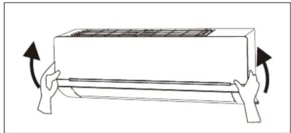
Step 10: Checking the Drainage
A. Open and lift the indoor unit front panel.
- Hold the lower part of the left and right sides of the panel, pull it against you and lift it until a click is heard.
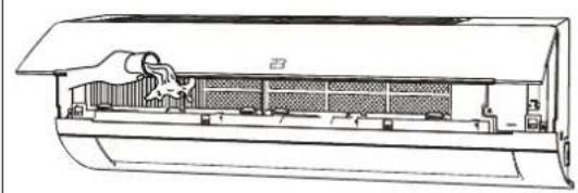
B. Check the drainage
- Carefully pour a glass of water on the evaporator.
- Ensure the water flows through the drain hose of the indoor unit without any leakage and goes out the drain exit.
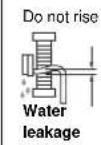
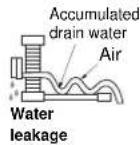
C. Dain piping
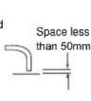
- The drain hose should point downward for easy drain flow.
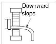
- Do not place drain piping as indicated below:

Step 11:Air Purging and Leakage Test
Air and moisture in the refrigeration system haveundesirable effects as indicated below:
System pressure increase.
- Operating current rise.
Cooling or heating efficiency drops.
- Moisture in the refrigeration circuit may freeze and block the capillary tubing.
Water may lead to corrosion of parts in the refrigeration system.
Therefore, the indoor unit and tubing between the indoor and outdoor units must be tested for leakage and evacuated to remove any noncondensables and moisture from the system.
Air Purging With Vacuum Pump
Preparation
Check that each tube (both liquid and gas side tubes) between the indoor and outdoor units have been properly connected and all wiring for the test has been completed. Remove the service valve caps from both gas and liquid sides on the outdoor unit.
- For detailed data of pipe length and refrigerant amount, please refer to page 6.

caution
- Both liquid and gas side service valves on the outdoor unit are kept closed at this stage.
- When relocate the unit to another place, performevacuation using vacuum pump.
Make sure the refrigerant added into the air conditioner is in liquid form in any case.
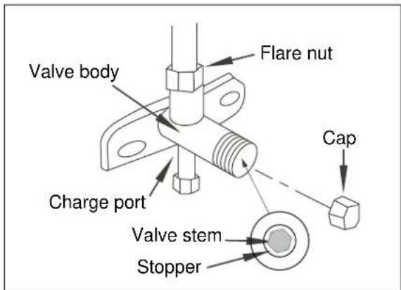
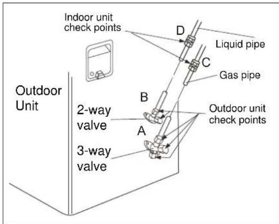
Caution in Handing the Stop Valve
Operation of opening stop valve: Open the valve stem until it hits against the stopper. Do not try to open it further.
Operation of closing stop valve: Securely tighten the valve stem with a special tool. Then securely tighten the valve stem cap with a spanner or the like.
Refrigerant

tips and information
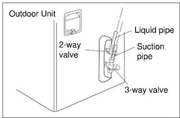
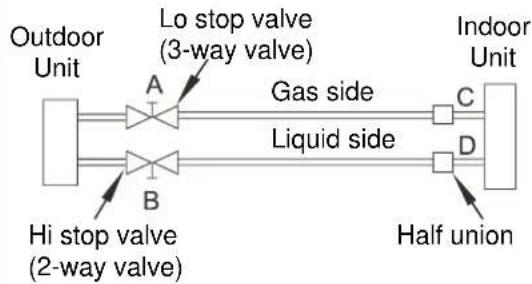
A: Low pressure valve (3-way) - gas side.
B: High pressure valve (2-way) - liquid side.
C and D: they are the ends of indoor unit connection
Refer to the valve cap tightening torque value as below:
| Outer diam. (mm) | Torque (N.m) | Additional Torque (N.m) |
| Φ 6.35 (1/4") | 15.7 (1.6kg.m) | 19.6 (2.0kg.m) |
| Φ 9.52 (3/8") | 29.4 (3.0kg.m) | 34.3 (3.5kg.m) |
| Φ 12.70 (1/2") | 49.0 (5.0kg.m) | 53.9 (5.5kg.m) |
| Φ 15.88 (5/8") | 73.6 (7.5kg.m) | 78.6 (8.0kg.m) |
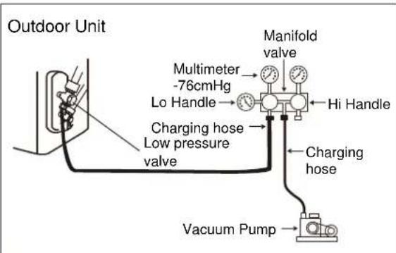
When Using the Vacuum Pump
1 Completely tighten the flare nuts on A, B, C and D, connect the manifold valve charge hose (blue) to the charge port of the low pressure valve (3-way valve) on the gas pipe side.
2 Connect the other charge hose (yellow) of manifold to the vacuum pump.
3 Fully open the handle Lo of the manifold valve.
4 Open the vacuum pump for vacuumization. At the beginning, slightly loose the flare nut of the low pressure valve to check if there is air coming inside (If operation noise of the vacuum pump has been changed, the reading of multimeter is 0 instead of minus). Then tighten the flare nut.
5 Keep vacuuming for more than 15 minutes and make sure the reading of multimeter is -1.0 × 10^5 ~Pa (-76cmHg). Then fully close the handle Lo of manifold valve and stop the operation of the vacuum pump.
6 Turn the stem of the stop valve B (2-way valve) about 45^ counterclockwise for 6-7 seconds after the gas coming out, then tighten the flare nut again. Make sure the pressure display in the pressure indicator is a little higher than the atmosphere pressure.
7 Remove the charge hose from the low pressure charge port.
8 Fully open the valve stems of A (3-way valve) and B (2-way valve).
9 Securely tighten the stem cap.
Test and Running
Gas Leakage Check
1 Soap water method:
Apply soap water or liquid neutral detergent on all valves and pipe connections (A, B, C and D, refer to the figure below) involved in installation by a soft brush to check for leakage.
If bubbles come out, the pipes have leakage.
2 Leak detector
Use the leak detector to check for leakage.
Electrical Safety Check
Perform the electric safe check after completing the installation:
1 Earthing work
After finishing earthing work, measure the earthing resistance by visual detection and earthing resistance tester.
2 Electrical leakage check
(performing during test running)
During test operation after finishing installation, the service person can use the electric probe and multimeter to perform the electrical leakage check. Turn off the unit immediately if refrigerant leakage happens. Check and find out the solution ways till the unit operate properly.
Operation Test
1 Before Operation Test
- Do not switch on power before installation is finished completely.
Electric wiring must be connected correctly and securely. - Stop valves of the connection pipes should be fully opened.
- All the impurities such as scraps and waste must be cleared from the unit.
2 Operation Test Method
- Switch on power and press "ON/OFF" button on the remote controller to start the operation.
- Press MODE button to select the COOL, HEAT (if applicable), FAN to check if all the functions work well.
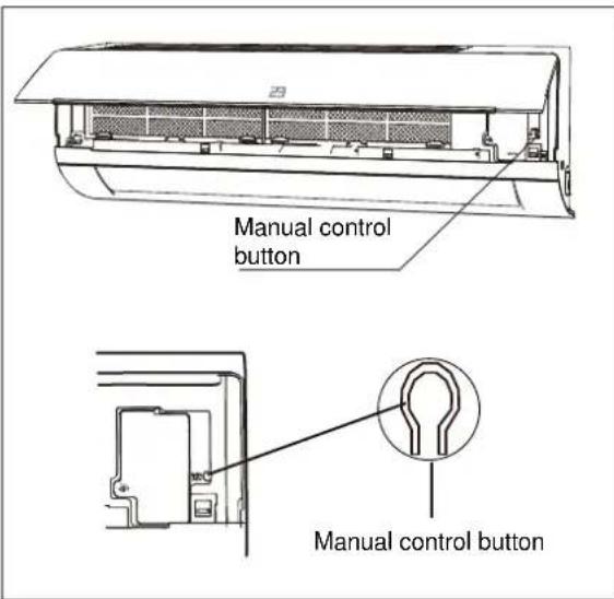
- When the ambient temperature is lower than 16^ , the unit can not be set on the remote control to work in COOL mode. Please use the Emergency Operation mode which is used only when the remote is unavailable or in case of maintenance.
Pump Done
When relocating or disposing of the air conditioner, pump down the system following the procedure below so that no refrigerant is released into the atmosphere.
- Connect the hose of manifold valve to the charge port of stop valve on the gas pipe side of the outdoor unit.
- Close the stop valve on the gas pipe side almost completely.
- Fully close the stop valve on the liquid pipe side.
- Turn on the unit in COOL mode.
- Fully close the stop valve on the gas pipe side when the pressure gauge shows 1 - 0.5kgf/cm^2 (100~50 kPa).
- Stop the test run operation by turn the unit off and all the refrigerant gas have been collected in the outdoor unit.
Check After Installation
| Items to be checked | Possible malfunction |
| Has the unit been fixed firmly? | The unit may drop, shake or emit noise. |
| Have you done the refrigerant leakage test? | It may cause insufficient cooling (heating) |
| Is thermal insulation sufficient? | It may cause condensation. |
| Is water drainage satisfactory? | It may cause water leakage. |
| Is the voltage in accordance with the rated voltage marked on the nameplate? | It may cause electric malfunction or damage the unit. |
| Is the electric wiring or piping connection installed correctly and securely? | It may cause electric malfunction or damage the parts. |
| Has the unit been securely earthed? | It may cause electrical leakage. |
| Is the power cord specified? | It may cause electric malfunction or damage the parts. |
| Is the inlet or outlet blocked? | It may cause insufficient cooling (heating) |
| Is the length of connection pipes and refrigerant capacity recorded? | The refrigerant capacity is not accurate. |
Felicitations
Pnnpopoeic aToppiyia Toux npoteC
Ta TepiooTopea aTo ta UAIka OuaKeuaiaeivai avakukwaija. Napakaaloue atoppipta Ta uIAkauTae oW Tou TOTIKOU Kevtpou avakukwongn TOITIOEHTNE Ta OTous KaataaAnouc kaoouc ouaoyns.
Eav eTIOUeIe va aTIOPIeTe auto To KAIJAOTIKO, ETTKOIVWvNToE ME TIG TOITIKc apXec KAI POtNoTE VIA Tn OwOt N eOdo aTIOPIuNs.
Συνθήκες χρήσς
Autn n ouakeun Tpoopicietai yia oikiakn xponkai Tapopoiec eapapoyes,OTTW:
Odbnyiecs yia to xwpo Eykataoans
O owoToc xwpoC EYkataoTaOns Eivai OnmuavTkoC yia Tn owtn kai aToteAeouatikn Aetoupyia Tns movadac.
Antopuyete touc eNcs xwpouc oTou:
EKTIEPTIOVTAI TINYECS UYNANCS OEPUOTNTAC, aTPOSC, EUPAEKTO AEPIO NTTNIKA UYPa.
EKTIEPTOVTAI NAEKTPoayvntiKa KUpaTa UynnG OUXVOTNTa aTPOaIOEoTTIAO, OuaKEuEs OUYKOANOG n IATPIKo EoTIAO.
- UTIAPXeI aepac eYaN ouyKevtpwn anatwV (OTWCS KovTa OE TApakTIE TEPIOXc).
o aepaegx1 moauvtheta iE biouxavikouc atpuoc kai eaaia.
o aepac TEPiEeI eIWdec aepio OTWc O IApatIKEc TEPIOXeS.
- uπápxi δiαβpwon n kaκn ποισnta αερα.
Eomegaikováδa
1 H éioooc kai éxoboc aepa TpeTc va bpiokovtai μakpi aTO eμTóbia. BebaiwTe tO i aepac μTOpéi va KukloopopnσeI σ e oLo to δμáTIO.
2 EπIεEVEvaXwpo oTou to vepo OuPTUKWmuTOc μTopei va aTOnpayyicetai Eukola kai OTou eivai EukoAn n ouvdeon μe Tnv EεwTepiKn mvad.
3 Eπλεξε ένα Αημείο Σου εἰναι μακρία πό τιαδία.
4 EπIεEVEva onμeio oTou o Toixoc eivai apkετa yepoia va uTOOtnpieTo TAnpeS bapoc kai tn dovnan ts muvadac.
5ΦoVtiOe va apnoTe apkeTo xwpo yia va eivai EukoAn n TpOaBaoN YIA TnV TaKTIKn Ouvtnponn. Tia BéAIOtn aTIOdoon, n EOWTEPIKn Movad A TpEeIva EYkataoTaBei OE ToIxO KAI OE UPOC 2 mtpowv n TEPiiooTePo pavw aTIO to dattelo, aaλa Liyotepo aTIO 2,5 metpa aTIO to dattelo.
6Φovtioge n eoWepikn moVadva evykataaTaThei ouqwva me TIC diaoTaeic yekataaotaon tsou npapathevtai napakatw:
7 EπiεξE eva Αημεio περιπou 1 m n TEPiσoσepeo μakpiατó tn σuokεuŋtns Tnλεραοηn aλλn nεktpiŋ κuokεuŋ.
8 Eπλεξτ ενα Αημειο ὄτου θα εΙναι εύκολη αραρεση του φιΑρου.
9 Mn xpoiooieTe novda oTo xpo Tou Tlauvtnpiou, KovTa OE TiOiva K.AT.
10 Attaitei mikos oWnva Toulaxiotov 3 etpww yia Tnv Elambdaottoinon Tnc dovnong kai tou oopou.
11 Xpnoiopoioote eva unxavnua EvToTIOou opooatawv ia tvn atoquyn n anatapaitntnc Znuiac oTov toxO.
12 OtoiaoTnToE TpoTTOiOn OTo mKoc oWAnva 0a/ITopei va aTtTe i puOmuon OTnv TAnpwoon uukTIkoU.
13 Mny Tny EkyataoTnoTe KovTa OE TiopTa.
Egwtepikn movda
1 Eπλεξε εva xwpo oTou o Θρuβος kai o Εερxóμενος αερας από ημoVáδa δεv θα ενoxλει Touc yεitovες.
2 Eπiλεξτ εva xωpo 6Tou UTTAPxE IETAPKns aεpiσμός.
3 EπλεξE εva χwpo ΕTou δεν Uπαpxouv εμτóδiaσtnv ειοδo kai TnV εξοδo.
4 O xwpoC TpTeTcVa mTPOeIva UTOOaTnpieEiTo TnApeC BApoc KAI Tn Dovnon TnMovadac.
5 EtIaEeEv aTeyv o nμeio, aλa μnν εκθεTETη μovadασ e aεo ngiaikó φως nixxupó avεμo.
6 Povtiote n eEwtepiKn ova da va EykataoTaThei oupwoa me TIC odnyiec EYkataaTaoNs KAI VA Eiva Boikni yia Epyaoiec ouvtnpnnc Ka ETIIOKEUNC.
7 EITIeEte eva onueio tou eivai paKpa aTIO taIdia kai paKpia aTio zwa n qut.
8 EπIeE Te eva onμeio Tou eivai paKpa aTTO TaIdia kai paKpia aTó cwa n qutá.
9 EπIαEε Teva onμeio oTou n movδa diatnpεiα σε opicovia kai eUθuypaμiαμevn θεοη.
10 Eπλεδε Ενα σημεο ὄτου έρουνται Ελαχιθες Ατοστάσεις γύρω Ατό Στην εξωτερική μονάδα Οτιώς Παρατίθεται Παρακατω: