Heatstrip - Heating GRANDHALL - Free user manual and instructions
Find the device manual for free Heatstrip GRANDHALL in PDF.

User questions about Heatstrip GRANDHALL
0 question about this device. Answer the ones you know or ask your own.
Ask a new question about this device
Download the instructions for your Heating in PDF format for free! Find your manual Heatstrip - GRANDHALL and take your electronic device back in hand. On this page are published all the documents necessary for the use of your device. Heatstrip by GRANDHALL.
USER MANUAL Heatstrip GRANDHALL
The heater that is a design f e a ture!

CONTENTS
Rev E Oct14
Product overview 3
Specifications 5
Spot heating principle 6
Radiant footprint 7
Product selection 8
Table layout 9
Installation requirements 10
Installation location 11
Mounting options 12
Standard mounting brackets 13
Flush mount enclosure 14
FME dimensions 15
FME installation clearance dimensions 16
FME installation instructions 17
Pole/beam mounting kit 18
Twin mounting bracket 19
End to end mounting bracket 20
Suspension mount bracket 21
Extension mount bracket 22
Wall controller w/ remote control 23
Wall control installation 24
Safety, Maintenance 25
Warranty 26
Product Overview
Why choose Heatstrip® electric radiant heaters for your outdoor or hard-to-heat indoor area?
As there is typically constant air movement in an outdoor or open indoor area, many conventional patio heaters rely on convection heating which works by heating the surrounding air. This can be quite impractical for these areas, as this heated air can easily blow away with natural air movement. Radiant style heaters transfer heat directly to objects through infra-red waves.
Whilst convection heaters heat the air in between objects, radiant heaters heat the surface of the objects themselves. HEATSTRIP® electric radiant heaters are more effective within an outdoor or uninsulated indoor area because they provide targeted warmth directly to the people and objects in their path.
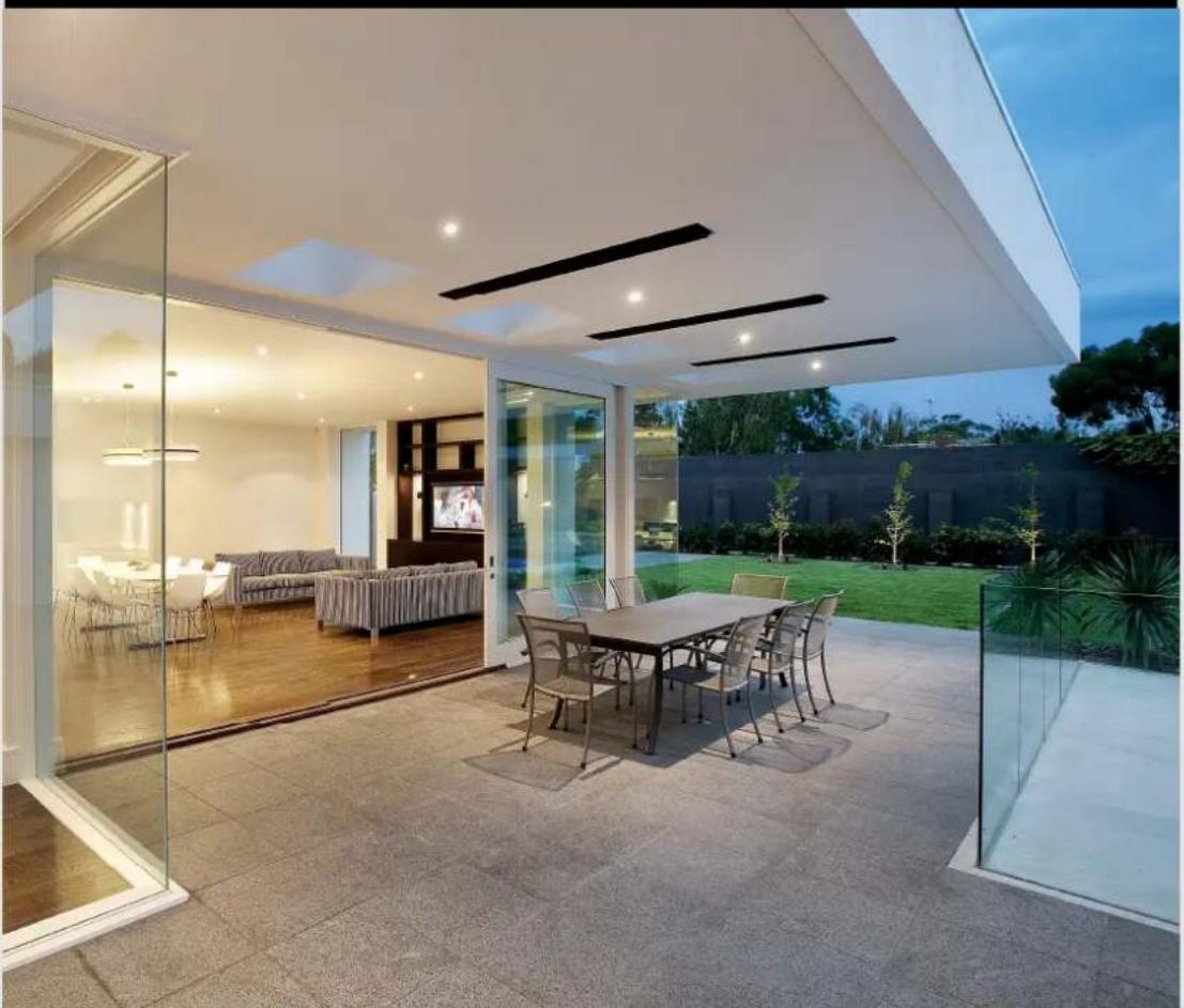
Discrete, stylish heating for undercover outdoor and indoor open areas
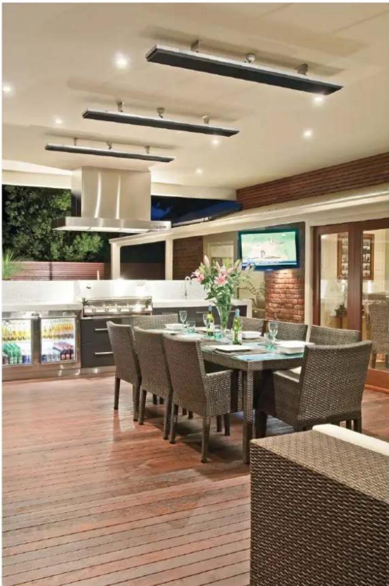
Using the radiant heating principle, HEATSTRIP® can provide effective and energy efficient comfort heating for undercover outdoor and indoor open areas. HEATSTRIP® has successfully enabled many entertainment venues such as restaurants, pubs and clubs to utilise their outdoor dining areas day and night, through all seasons. Within your workplace or business, HEATSTRIP® can provide comfort heating for designated outdoor smoking and leisure areas, as well as for workstation spot heating in factories, warehouses and showrooms. Within your home, HEATSTRIP® can provide comfort heating for undercover alfresco dining and BBQ area, patios, verandas, courtyards and balconies.
Subtle, minimalist design
The stylish, slimline black face of the HEATSTRIP® does not emit light or glow when in use, blending elegantly into your decor. Ceiling, wall and umbrella mounting options ensure that your valuable floor and table space is not wasted.
There are 3 different series of products within the Heatstrip® product category. Each has a different temperature output, making them ideal for different applications. Below is a list of some common applications, to assist with the selection of the most effective and efficient series. This is a general guide only, please refer to the Product Manual for each product, for more information.
HEATSTRIP® Max (THX models) is an ultra high temperature heater used for uncovered or open areas with a mounting height of 2.4 m to 3.5m.
HEATSTRIP Design (THH models) is a premium high temperature heater and is primarily used for outdoor rooms where there is 1,23, or 4 enclosed sides, with an ideal mounting height of 2.1m to 2.7m .
HEATSTRIP® Indoor (THS models) is a medium intensity heater used for protected indoor applications.
APPLICATION THX THH THS
| Indoor insulated areas, classrooms, offices, bathrooms, wet areas, drying rooms | X √ | √ | |
| Outdoor under cover, café, veranda, patio, balcony ceiling height 3m or less | X √ | X | |
| Outdoor under cover, café, veranda, patio, balcony ceiling height 3m or more | √ X | X | |
| Highly exposed outdoor area | √ X | X | |
| Indoor open area, warehouse, factory, production areas, sports facilities | √ √ | √ | |
| Indoor spot heating, above tables, assembly areas | √ √ | X |
Efficient, cost effective electric heating
The innovative design of the HEATSTRIP® enables comfortable and even heat dispersion from the surface with minimal operating costs.
Design flexibility
Three HEATSTRIP® models are available, ensuring the heating requirements of any undercover outdoor or open indoor area is possible. Brackets for direct ceiling or wall/ceiling angled mounting are supplied as standard. Optional HEATSTRIP® accessories include beam or fixed umbrella mount brackets, extension mount brackets, chain suspension brackets, twin mount brackets and flush mounting enclosures.
Minimal maintenance
The HEATSTRIP® incorporates no internal moving parts ensuring quiet and virtually maintenance free operation.
Australian made
Designed, engineered and assembled in Australia the HEATSTRIP®.
Stylish design—The Heater that is a Design Feature!
The attractive HEATSTRIP Design comes with a standard black face and anodised alloy rear casing.
Easy to use
The HEATSTRIP is controlled by a simple on/off operation, either when plugged directly into a power point, or hard-wired via a wall mounted on/off switch. The unit takes approximately 15 minutes to heat up to maximum temperature and approximately 30 minutes to cool down, depending upon the ambient temperature. Please don't forget to turn it off.
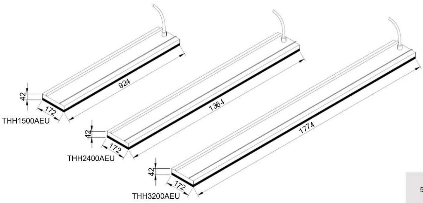
Specifications - Europe
| MODEL POWER (WATTS) | CURRENT (AMPS) | VOLTAGE (VOLTS) | DIMENSIONS (mm) | WEIGHT (Kg) | LEAD LENGTH (mm) | PLUG | |
| THH1500AEU | 1500 5.9 | 230 | 924 x 165 x | 48 5 1000 YES | |||
| THH2400AEU | 2400 12.3 | 230 | 1364 x 165 | x 48 6 1000 YES | |||
| THH3200AEU | 3200 | 12.5 | 230 | 1774 x 165 x 48 | 8 | 1000 | NO |
| THH1500AUK | 1500 6.1 924 | x 165 x 48 5 1 | 000 YZSS | ||||
| THH2400AUK | 2400 9.8 136 | x 165 x 48 6 | 1000 24BS | ||||
| THH3200A | 3200 13.0 177 | x 165 x 48 8 | 000 240 | NO | |||
| HEATER TYPE | High intensity electric radiant overhead heater with high surface area profiled alloy | ||||||
| OUTPUT | Refer to model code chart above | ||||||
| POWER | 230-240 Volts Nominal at 50-60 Hertz, Single Phase | ||||||
| CONNECTION | 3 Core Cable 2.5mm² | ||||||
| APPROVALS | CE | ||||||
| MOUNTING HEIGHT | MINIMUM | 2.1 m | |||||
| RECOMMENDED | 2.3 m to 2.7 m | ||||||
| MAXIMUM | 3.0 m (For higher ceiling heights, units can be lowered using optional bracket kits or refer to the Heatstrip Max range) | ||||||
| MOUNTING OPTIONS | Suitable for ceiling, wall, beam, fixed umbrella and recess mounting. Also available for extension mount using rigid fixing poles and chain mount bracket. | ||||||
| PROTECTION RATING | IP55 Protection from water ingress from all directions | ||||||
| COUNTRY OF MANUFACTURE | Australia | ||||||
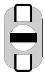
Spot heating principle
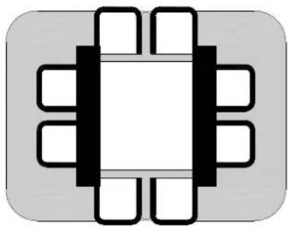
In most outdoor or difficult-to-heat indoor applications, therefore are 2 options when looking at the size and quantity of the heater required. Option 1 is to comfort heat the entire area based on the total dimensions of the space, regarding of whether the entire area is being fully occupied. Option 2 is to spot heat the high use areas, such as over outdoor tables, BBQ's, lounges, assembly lines or indoor workstation.
Often it is more practical and efficient to spot heat these areas. Spot heating will help to reduce the initial capital cost, as well as the running costs. Spot heating will allow the area to be "zoned", meaning heating only the areas that are being used, such as tables in a restaurant or outdoor alfresco area.
The top table shows a comparison between spot heating over a table, or heating an entire area.
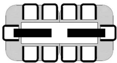
The bottom table shows the flexibility of using HEATSTRIP® to provide a comfortable environment, even when the layout of the area is very unusual.
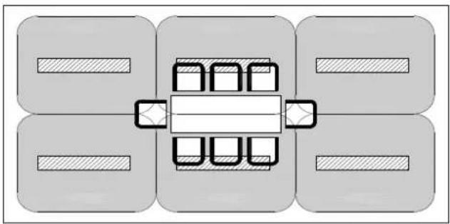
6 x THH2400AEU 2 x THH2400AEU
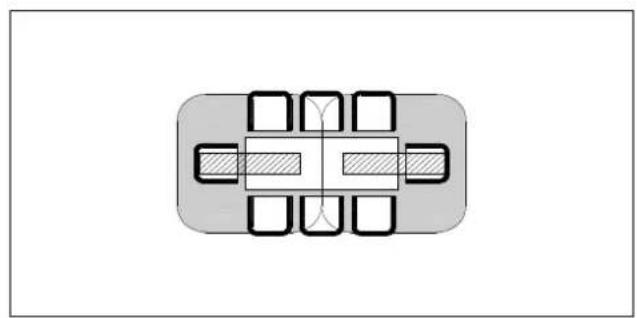
2xTHH24006xTHH2400
Radiant footprint
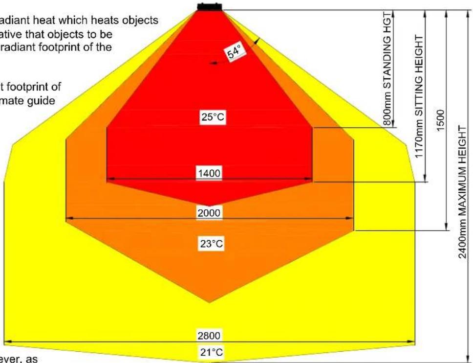
HEATSTRIP® electric heaters produce radiant heat which heats objects rather than the air. Therefore, it is imperative that objects to be heated (ie. people), are within the direct radiant footprint of the heater.
The diagram to the left shows the radiant footprint of HEATSTRIP Design, and is an approximate guide based on a fully enclosed, outdoor environment.
This diagram shows that the maximum heat output is found directly under the heater, and the temperature decreases as you move away from the heater. It highlights the importance of maintaining recommended mounting heights, and if possible, positioning the heater directly above the area to be heated.
Also, the temperature (ie. surface temperature) is the same for all 3 models, regardless of the wattage. However, as
the size increases and the length of the unit increases, the radiant footprint will be larger.
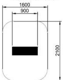
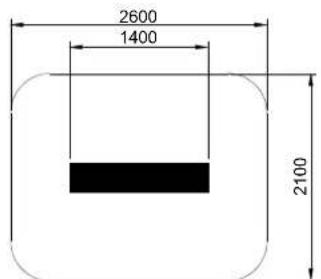
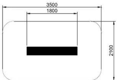
The below diagrams show the approximate heating area for each model, based on both an indoor and outdoor enclosed environment, with direct overhead mounting.
Radiant footprint is reduced in angled, wall mounted applications.
HEATED AREA
INDOOR SPOT HEATING
THH1500AEU
THH2400AEU
THH3200AEU
HEATED AREA
OUTDOOR ENCLOSED AREA
THH1500AEU
THH2400AEU
THH3200AEU
Selection guide
Prior to selecting the exact model and quantity required for your application, please ensure the correct range of Heat strip heaters is being used.
Below is an overview of the Heat strip options.
HEATSTRIP® Max (THX models) is an ultra high temperature heater used for uncovered or open areas with a mounting height of 2.4 m to 3.5 m. Also suitable for difficult indoor environments such as showrooms, production lines, warehouses etc.
HEATSTRIP Design (THH models) is a premium high temperature heater and is primarily used for outdoor rooms where there is 1,23 or 4 enclosed sides, with an ideal mounting height of 2.1m to 2.7m . Ideal for hard to heat indoor applications or moist environments where an IP55 rating is required.
HEATSTRIP® Indoor (THS models) is a medium intensity heater used for protected indoor applications, such as sunrooms, school classrooms, halls, gymnasiums etc.
General recommendations for HEATSTRIP Design:
- Ideal mounting height: 2.1m to 2.7m. Maximum is 3m in a protected outdoor environment.
Ideal mounting location: ceiling mounted, directly above area to be heated (eg. above a table) - Based on the radiant footprint of the previous page, for a protected outdoor area, a minimum of 500W / m2 is required. For indoor spot heating, a minimum heating capacity of 400W / m2 is recommended.
The below table outlines the coverage of each HEATSTRIP Design model (in ^2 ), based on 3 different scenarios, with direct overhead mounting. For example, for an outdoor area that is protected from prevailing winds by walls, café blinds etc, Model THH1500AEU will cover 3m^2 and Model THH2400AEU will cover 4.8m^2 .
For angled wall mounting applications, the coverage can be reduced by up to 40% . The maximum heat projection from the wall is 2m .
| MODEL INDOOR PROTECTED (m2) OUTDOOR ENCLOSED (m2) OUTDOOR EXPOSED (m2) | |||
| THH1500AEU | 3.75 3 2.5 | ||
| THH2400AEU | 6 4.8 4 | ||
| THH3200AEU | 8 6.4 5.3 | ||
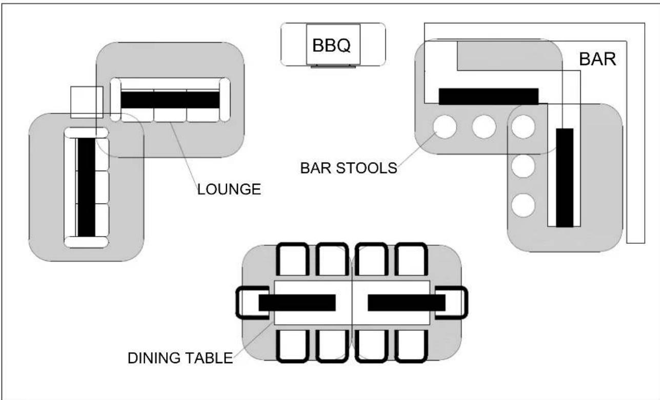
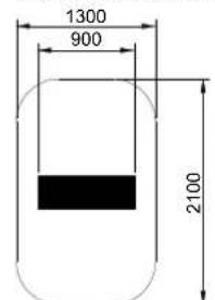
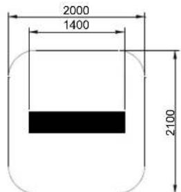
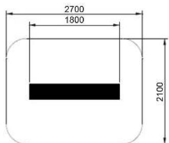
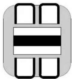
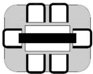
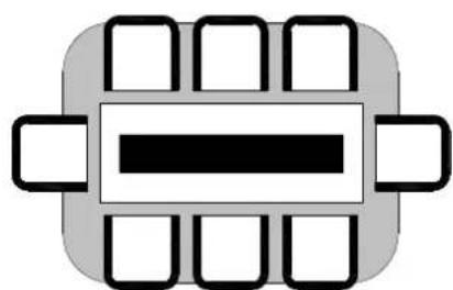
Table layout
For the majority of outdoor applications, the most effective method is to spot heat a table or similar area. The below diagrams provide an easy selection guide for the approximate model and quantity of heaters required to heat common residential table settings.
Selections are based on HEATSTRIP Design being mounted at 2.4m from the floor and an undercover fully enclosed outdoor area.
THH1500AEU

THH2400AEU
THH2400AEU
THH3200AEU
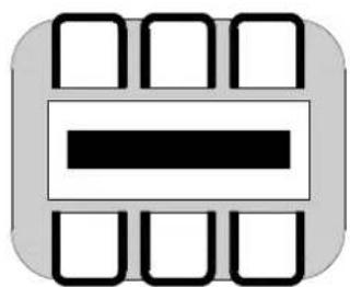
THH3200AEU
THH3200AEU
2×THH3200AEU
2×THH2400AEU
Installation Requirements
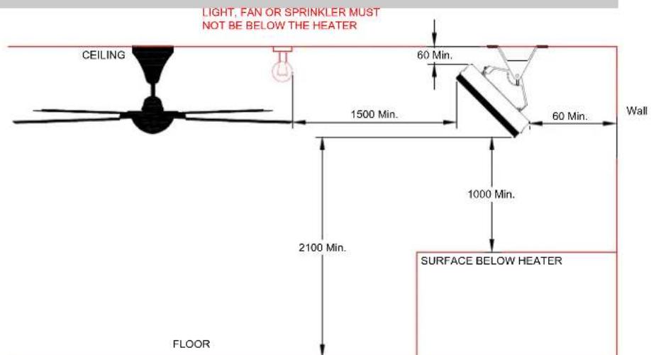
The ideal mounting position for the HEATSTRIP® Design is on the ceiling, directly above the area to be heated. If this is not possible, HEATSTRIP® can be mounted on a wall and angled downwards. In this situation, ensure the mounting height is in the range of 2.1m to 2.7m and the table is within 2.5m of the wall.
For mounting heights more than 3m we recommend the use of the optional accessories to reduce the height of the heater to 2.3m - 2.7m . This will increase the effectiveness of your HEATSTRIP® Refer to the Mounting Accessory section for more information.
Electrical connections/GPO's should not be located at the back of the heater. They should be located outside the physical footprint of the units to minimize heat build-up behind the units.
If the heater is to be mounted on an incline (eg. Vaulted ceiling), ensure the electrical connection is located at the lowest point of the heater.
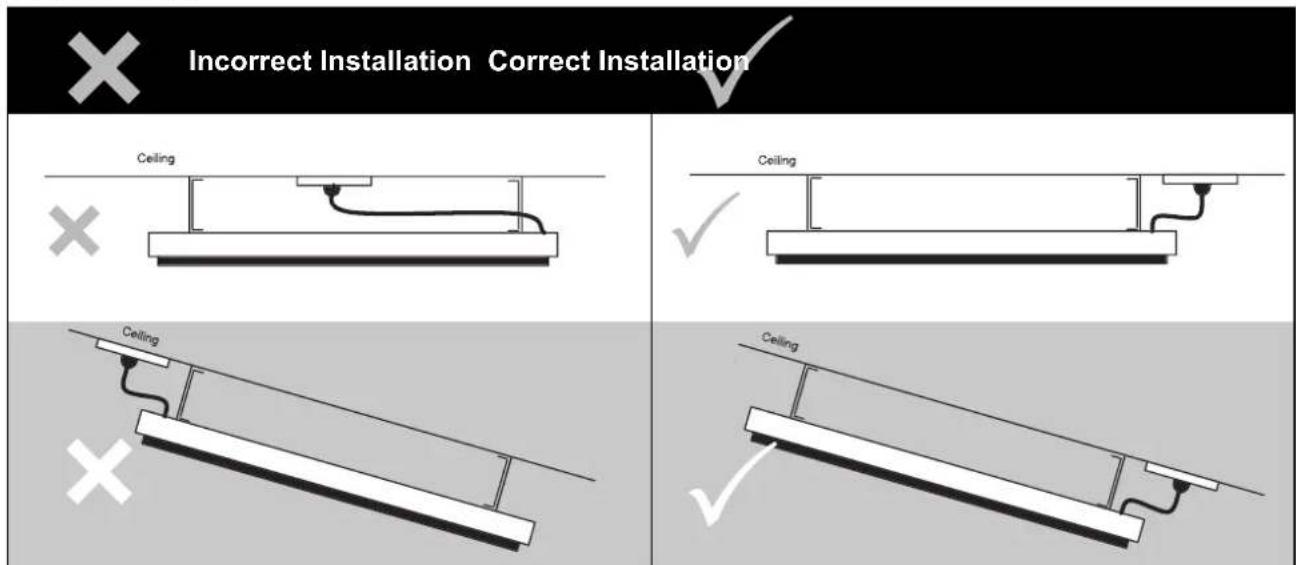
CEILING

The heating surface must never be directed toward the ceiling
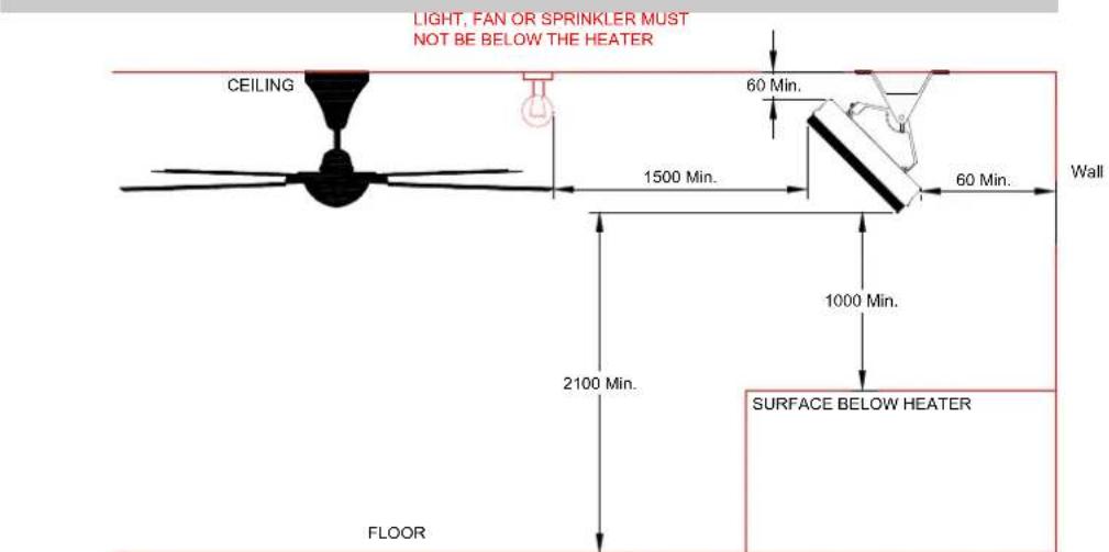
Installation location
the below diagrams confirm the minimum recommended clearances.
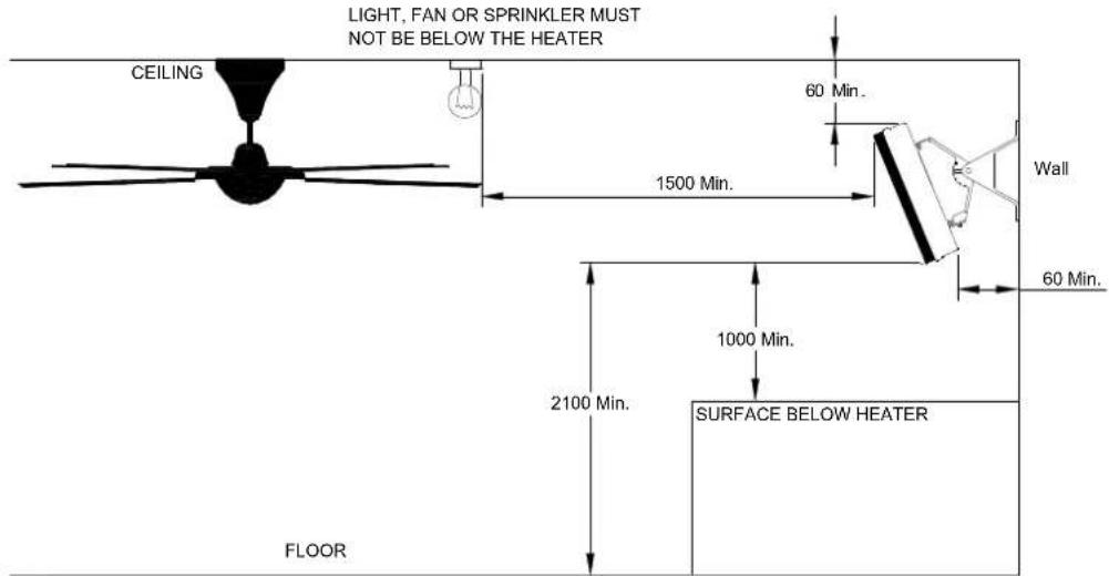
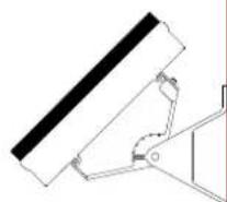
ANGLED WALL INSTALLATION
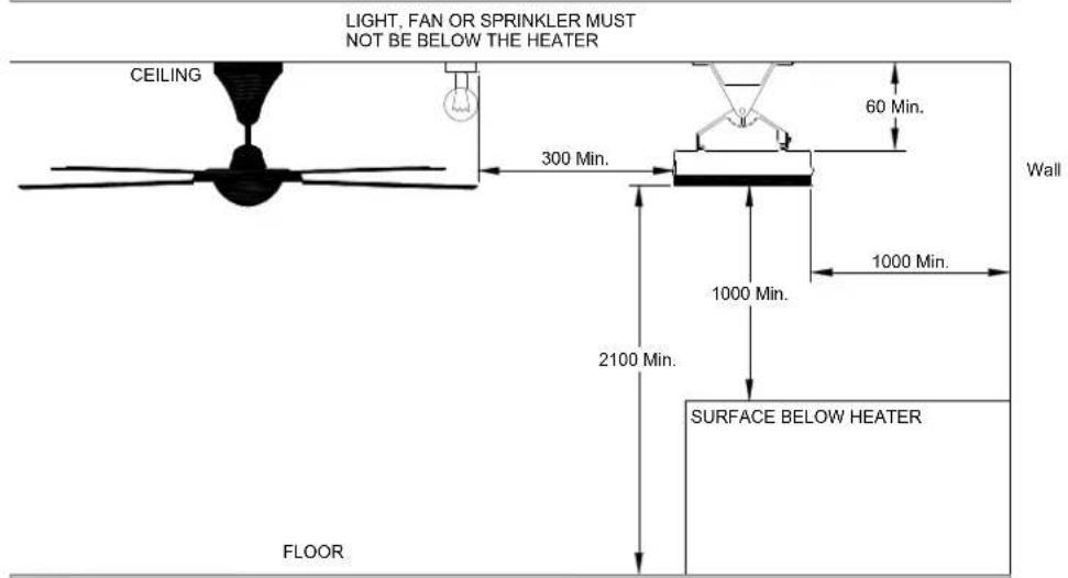
CEILING INSTALLATION
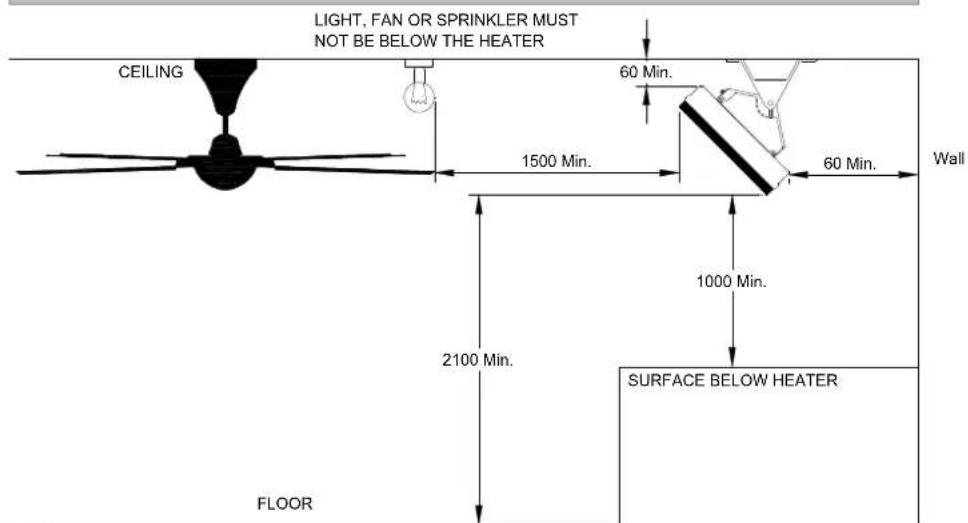
ANGLED CEILING INSTALLATION
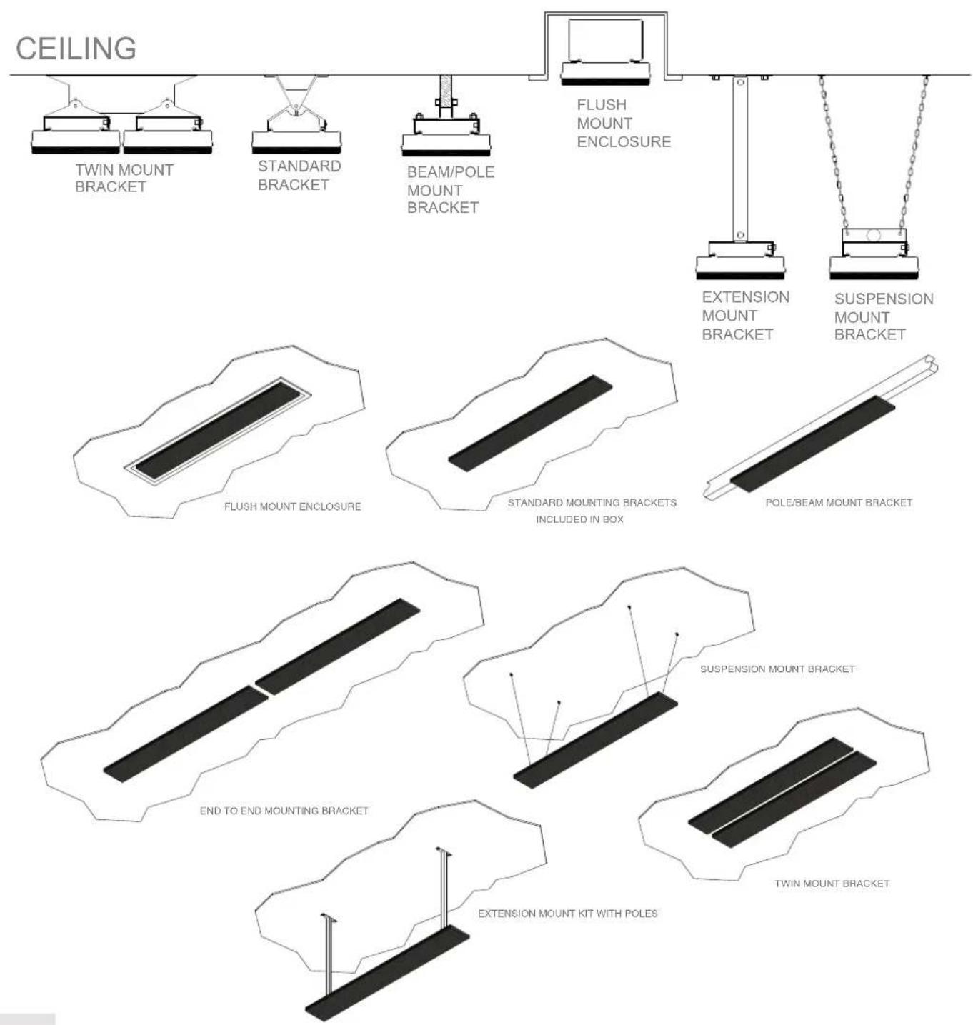
Mounting options
The installation of HEATSTRIP Design is simple and easy with the standard mounting brackets supplied. For other more challenging locations there are a range of mounting options available - refer to below diagrams.
The HEATSTRIP Design can be mounted directly to the ceiling, angled downwards on a wall, fitted flush with the ceiling; suspended on chains or poles; attached to beams or poles; mounted end-to-end, or 2 units together. Refer to the following pages for more detailed information on each mounting option.
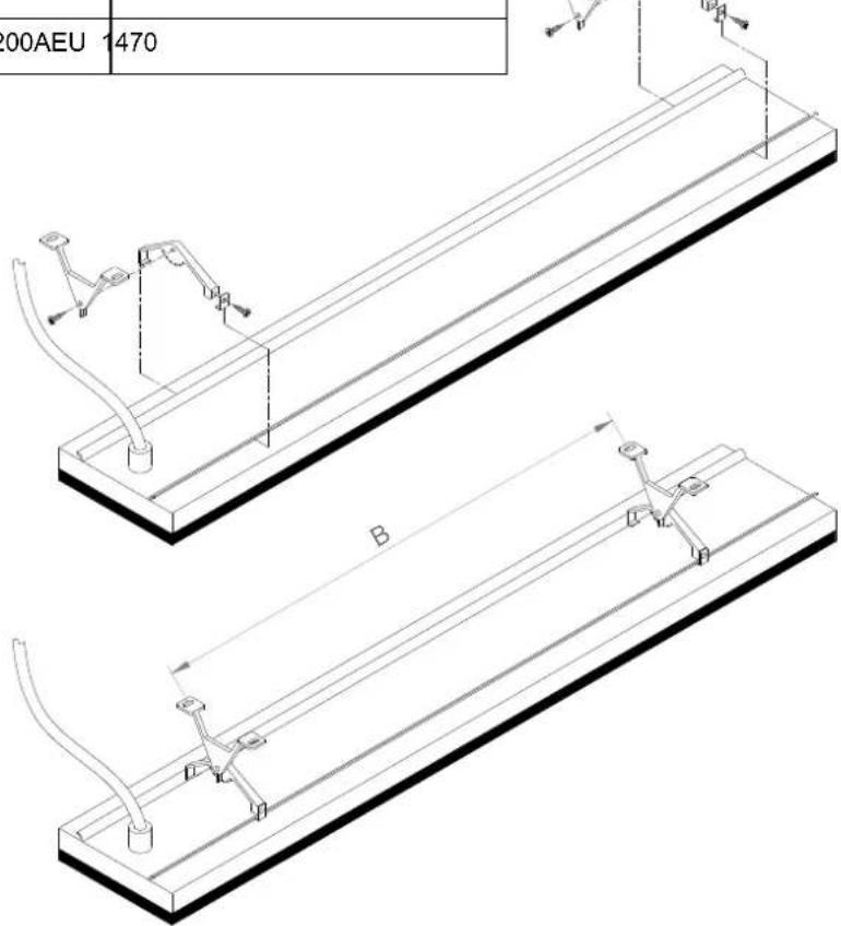
Standard mounting brackets
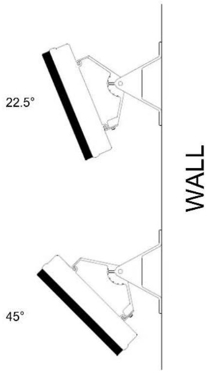
The HEATSTRIP Design comes with a pair of standard mounting brackets. These adjustable brackets allow direct ceiling or wall mount, and come with preset angle options of parallel, 22.5^ and 45^ .
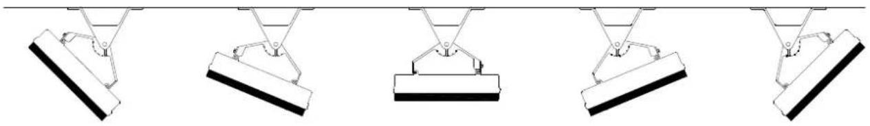
CEILING
PARALLEL 22.5^45^45^22.5^
| MODEL “B” MINIMUM DISTANCE (mm) | |
| THH1500AEU | 550 |
| THH2400AEU | 1000 |
| THH3200AEU | 1470 |
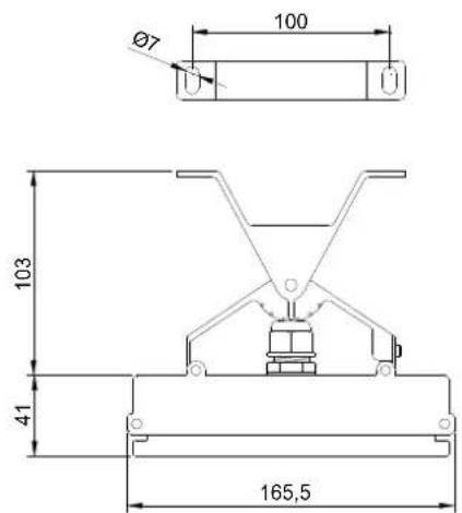
| PART No | PACKAGED DIMENSIONS (mm) | WEIGHT (kg) | MATERIALS |
| ZBRAK-103 | 125 x 150 x 40 0.2 | ALLOY |
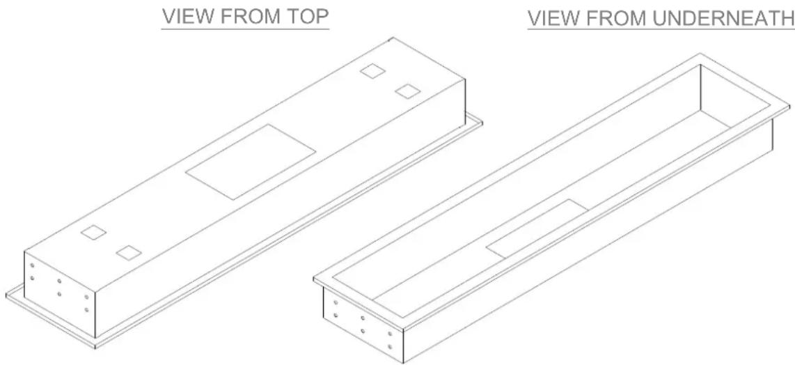
Flush mount enclosure
The Flush Mount Enclosure is an ideal way to neatly install the HEATSTRIP Design into a ceiling. They are available for all HEATSTRIP Design models, and are supplied as a one-piece unit for mounting of heaters. Flush mounting can be used with plaster or wood lined or concrete ceiling materials.
An ideal mounting height is 2.5m - 2.7m with a maximum ceiling height of 3.0m in an outdoor enclosed environment. Maximum mounting heights should be strictly followed, otherwise the performance of the units may be reduced.
The facia of the enclosure is manufactured from 316 Stainless Steel and the rear casing is black zinc coated steel. Please refer to the Installation Manual for more detailed installation information.
Safety
Do not allow any cables, furnishings, flammable materials or other items come in contact with any surface of the Flush Mount Enclosure.
The Flush Mount Enclosure needs to be installed as per the installation instructions paying special attention to the minimum clearances. The heater needs to be mounted on a rigid bracket or fixing.
Maintenance Flush Mount Enclosure
The Flush Mount Enclosure is made from durable materials, however regular care and maintenance of your product will help prolong its life.
It is recommended that you wipe down your Flush Mount Enclosure and with a soft cloth gently wipe the surfaces of the Flush Mount Enclosure with a mild detergent to remove the built up contaminants from the environment. Then with a clean cloth ensure all detergent is removed.
All chemicals in the atmosphere including cigarette smoke, pollution etc. will tarnish the surface of the Flush Mount Enclosure. In this case, additional cleaning and maintenance may be required. The cleaning process at least every three months will reduce the amount of build up and keep it looking as best it can. If the Flush Mount Enclosure is in a corrosive environment eg. salt spray, we recommend that you clean the Flush Mount Enclosure every week.
Before cleanings or inspection activity, the heater must be switched off and cooled down completely.
Do not use any abrasive materials or products to clean the Flush Mount Enclosure, this includes solvents, citrus based cleaners or other harsh cleaning products.
When handling the Flush Mount Enclosure, ensure that your hands are clean or that you use clean gloves as grease or dirt can mark the surface of the heater.
Do not use high pressure water to clean Flush Mount Enclosure. It is not recommended to hose down the Flush Mount Enclosure and heater as water may get into the roof cavity.

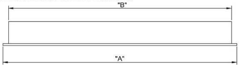
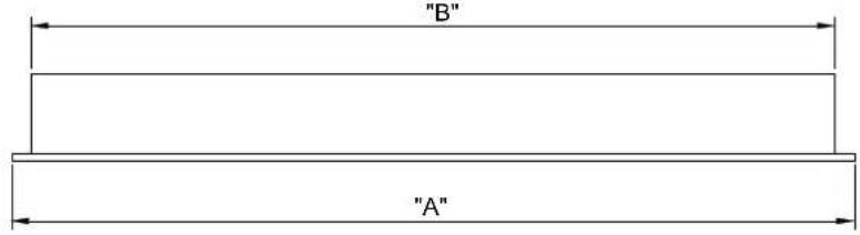
Flush Mount Enclosure
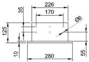
| PART No “A” (mm) “B” (mm) “C” (mm) | |||
| THHAC-009 | 1030 974 | 970 | |
| THHAC-011 | 1470 1414 | 1410 | |
| THHAC-012 | 1880 1824 | 1820 | |

| SUITABLE FOR MODELS | PART No | HOLE CUTOUT DIMENSIONS (mm) | OVERALL DIMENSIONS (mm) | WEIGHT (kg) | |
| THH1500AEU | THHAC-009 | 9 | 80 x 230 | 1030 x 280 x 125 | 5.5 |
| THH2400AEU | THHAC-011 | 1420 x | 230 | 1470 x 280 x 125 | 8 |
| THH3200AEU | THHAC-012 | 1830 x | 230 | 1880 x 280 x 125 | 9 |
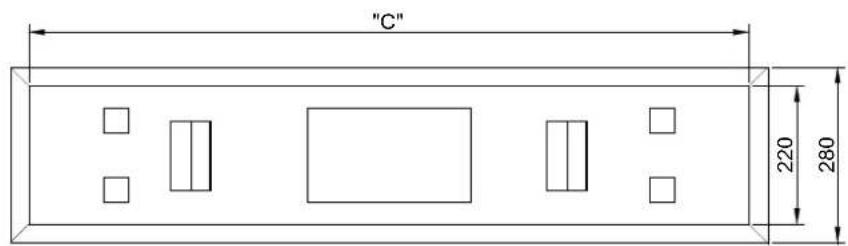
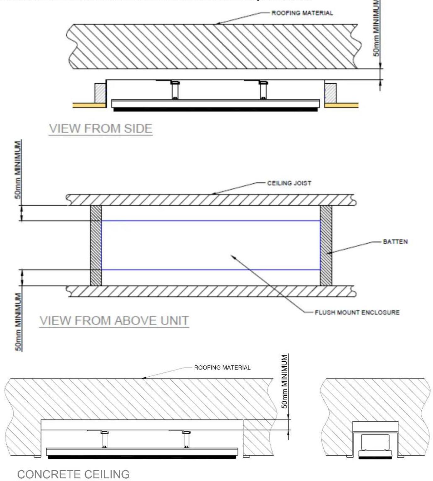
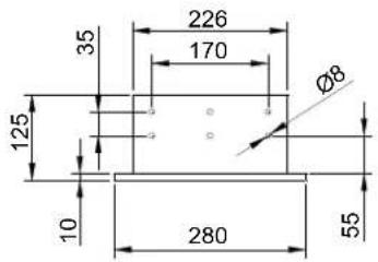
Flush Mount Enclosure installation clearance dimensions
Shown in the diagrams below are the minimum clearance required for the installation of the Flush Mount Enclosure.
It is imperative that all cables, backing materials, insulation and other materials are keep clear of the back and the sides of the Flush Mount Enclosure. The clearance dimensions are the same for all building rated materials.
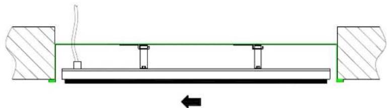
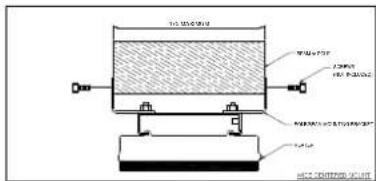
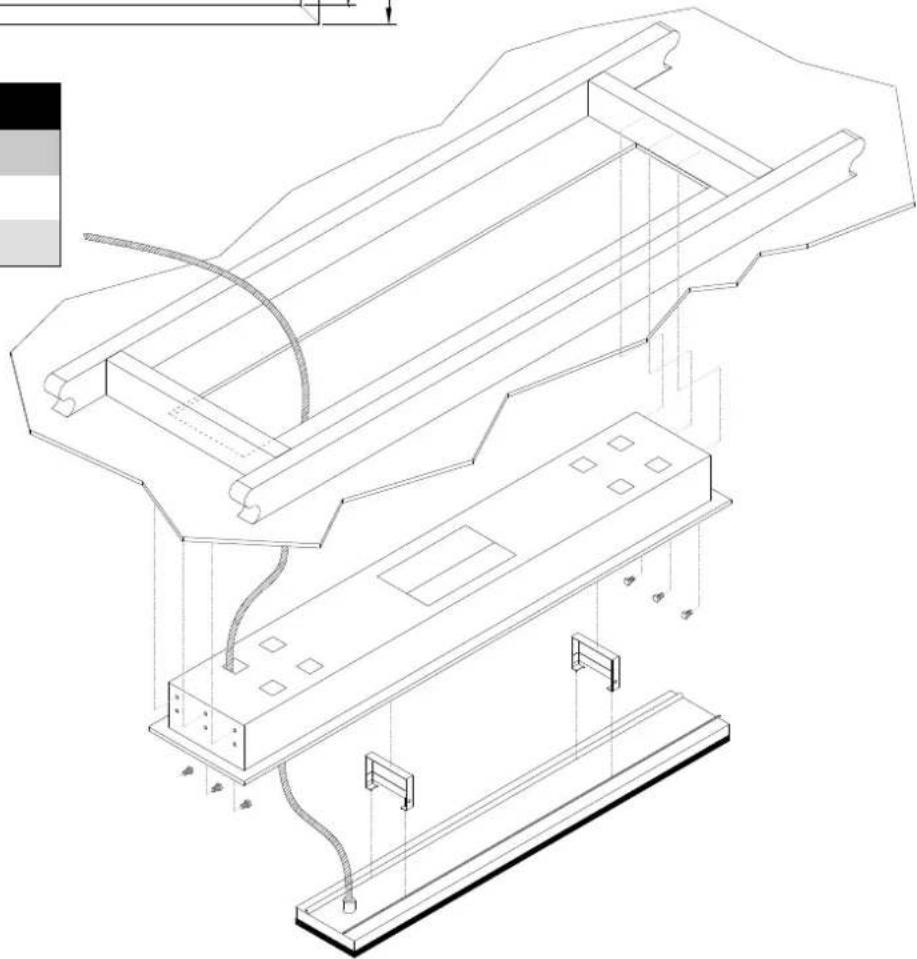
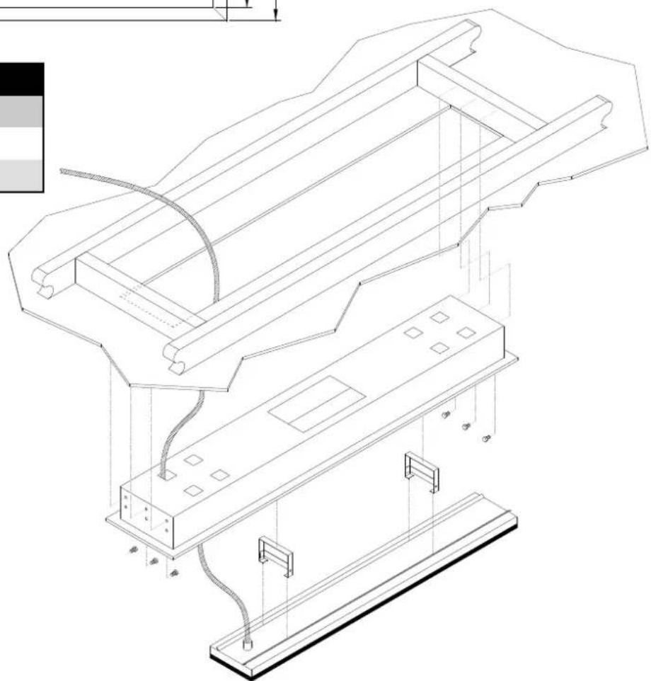
Installation instructions
Ensure all minimum clearance requirements are met and the materials used are compliant to your local building codes.
Before installing the Flush Mount Enclosure, ensure the site to be fixed is fully prepared with the hole cut the correct size and the mounting points securely in place.
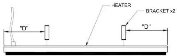
| MODEL | “D” DISTANCE FROM END TO BRACKET (mm) |
| THH1500AEU | 150 |
| THH2400AEU | 370 |
| THH3200AEU | 425 |
STEP 1: Attach the brackets to the rear of the heater. The dimensions for the spacing of the brackets is listed in the table.
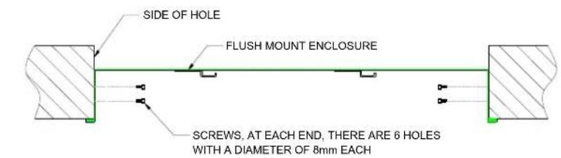
STEP 2: Screw the Flush Mount Enclosure into the side of the hole. NOTE: screws are not included.
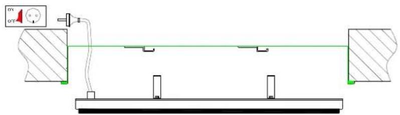
STEP 3: If there is no roof access, connect the heater to the power source, ensure the power is OFF.
STEP 4: Lift the heater into the Flush Mount Enclosure ensuring the brackets are to the side of the mounts
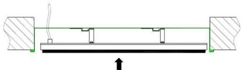
STEP 5: Push the heater to the left ensuring the brackets engage in the mounts. It will then drop in. Shake the heater to ensure that it is securely mounted.
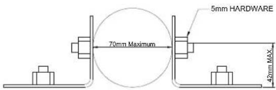
Pole / beam mounting kit
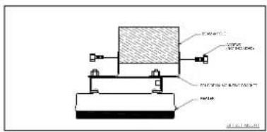
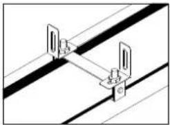
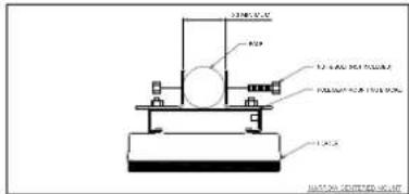
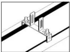
Screws for connection to the beam or pole are not included.
Minimum pole diameter 20mm.
Maximum pole diameter 70mm.
This mounting option is suitable for umbrella struts.
The beam/pole can be placed directly on top of the mounting bracket. No clearance is required from the top bracket to the bottom of beam/pole.
The optional Pole/Beam mounting bracket kit can be used to mount HEATSTRIP Design onto wooden beams, rafters, poles, umbrellas strutts etc.
| PART No | PACKAGED DIMENSIONS (mm) | WEIGHT (kg) | MATERIALS |
| THHAC-001 | 150 x 150 x 50 0.5 | 316 SS |
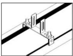
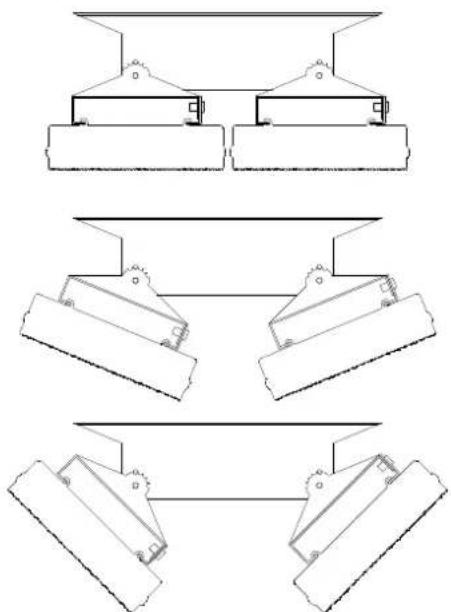
Twin mounting bracket
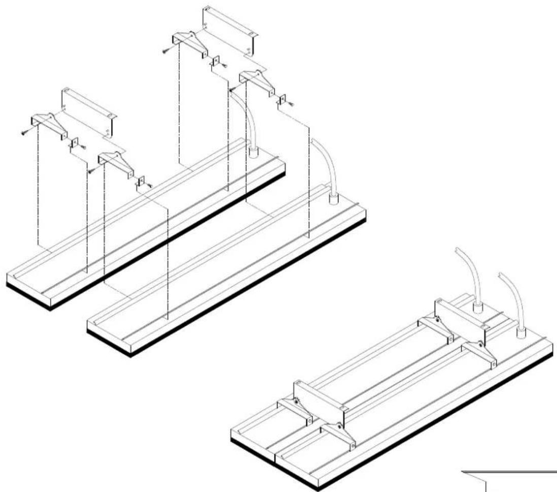
The optional Twin Mount bracket allows for two (2) units of HEATSTRIP Design to be mounted side-by-side, either in parallel or angled as per the diagram on the right. This is ideal for applications when a wider heat coverage is required, or when there is mounting restrictions/limitations (such as running between 2 rows of tables etc.)
The Twin Mount bracket can also be used with the Extension Mount bracket and Pole Kit, to lower the units from a high ceiling.
| PART No | PACKAGED DIMENSIONS (mm) | WEIGHT (kg) | MATERIALS |
| THHAC-016 | 300 x 50 x 50 | 0.25 | 316 SS |
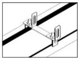
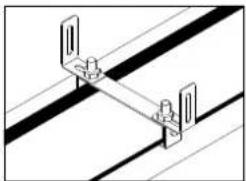
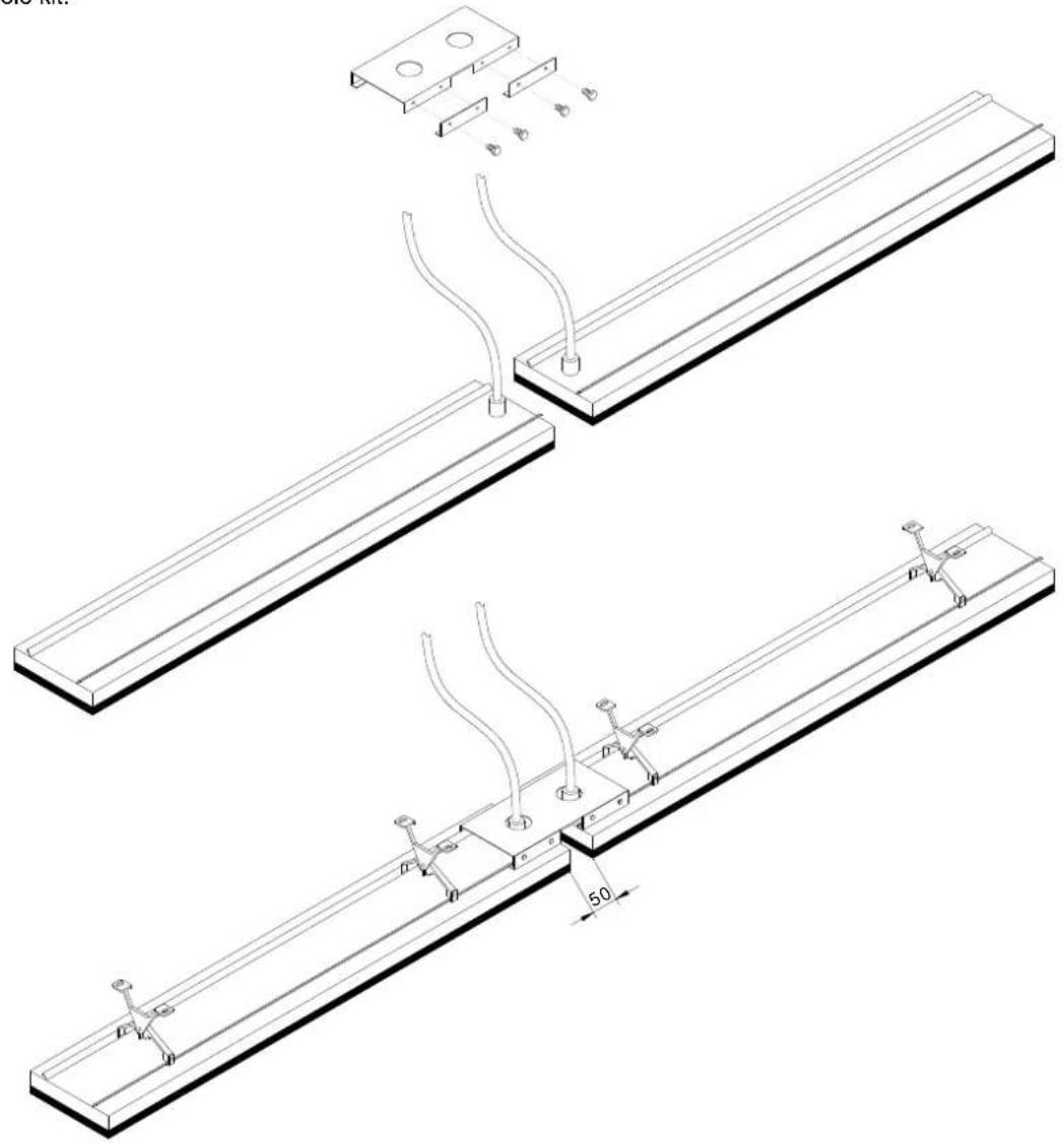
End to end mounting bracket
The end to end bracket allows multiple units to be joined in a straight line for maximum heat performance and aesthetic appeal. This is ideal for applications such as long rows of tables and assembly lines, where a constant heat coverage is required.
The bracket allows for a 50mm gap between units and an opening for the power connection. As per the diagram below, units should be mounted with the power leads together.
The end to end bracket can be used with either the standard ceiling/wall mount bracket or the extension bracket & pole kit.
| PART No | PACKAGAED DIMENSIONS (mm) | WEIGHT (kg) | MATERIALS |
| THHAC-017 | 300 x 150 x 50 0.5 | 316 SS |
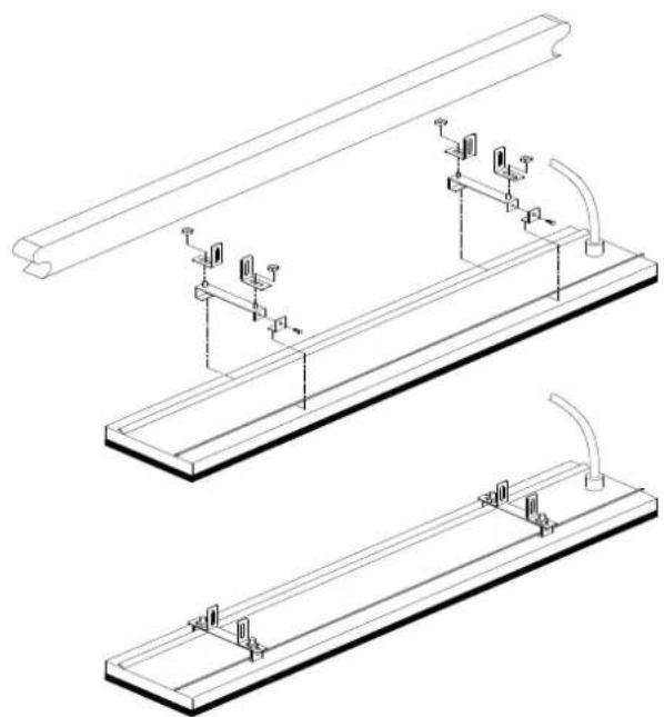
Suspension mount bracket
The Suspension Mount bracket provides a cheap, easy and effective option for lowering the HEATSTRIP Design from high ceilings. If the ceiling height is more than 3.0m is an enclosed outdoor environment, or 2.7m in an exposed site, it is recommended to lower the heaters to an ideal mounting height of 2.3m-2.7m . The bracket is designed to be used with chains or wires. There can be multiple chain/wire arrangement options, as per the below diagram.
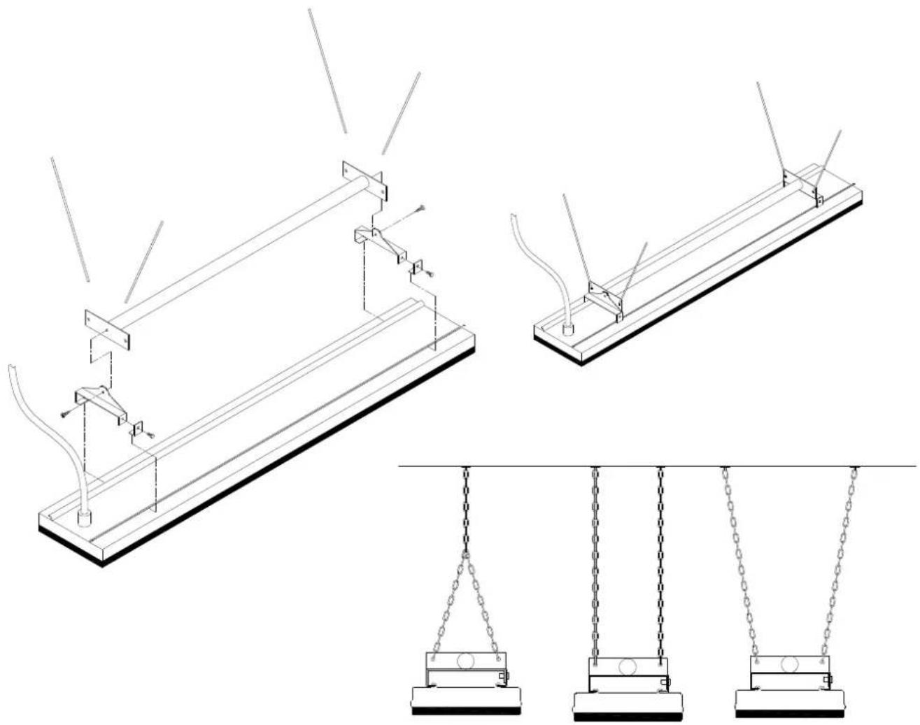
Note: chains or cable are not supplied with the heaters
| SUITABLE FOR MODELS | PART No | PACKAGED DIMENSIONS (mm) | WEIGHT (kg) | MATERIALS |
| THH1500AEU | THHAC-002 700 x | 150 x 50 1 | 316 SS | |
| THH2400AEU | THHAC-003 1200 | x 120 x 50 2 316 SS | ||
| THH3200AEU |
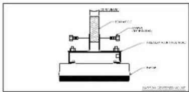
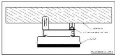
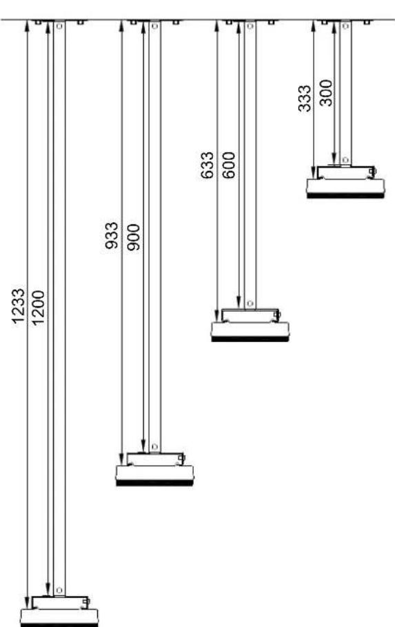
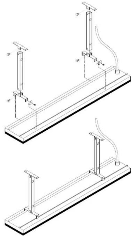
Extension Mount Bracket
The Extension Mount bracket allows HEATSTRIP Design units to be lowered from high ceilings, using rigid connections. The brackets are for use with 25mm × 25mm × 1mm tube (SHS), and can be supplied as brackets only for customising the length of the drop on site; or supplied as a complete kit with brackets, pre-cut poles and connections. The standard length options as part of the kit are 150mm , 300mm , 600mm and 1200mm .
The kits include all brackets, poles and screws necessary for connection to the heaters, however it does not include screws for attachment to the ceiling.
| PART No | PACKAGED DIMENSIONS (mm) | WEIGHT (kg) | MATERIALS | NOTES |
| THHAC-004 | 150 x 150 x 50 1 316 SS | Brackets only (for use with 25x25x1mm tube) | ||
| THHAC-005 | 300 x 150 x 50 2 316 SS | Kit includes 2x300mm extension pole, screws and brackets | ||
| THHAC-006 | 600 x 150 x 50 2 316 SS | Kit includes 2x600mm extension pole, screws and brackets | ||
| THHAC-007 | 900 x 150 x 50 2.5 | 316 SS | Kit includes 2x900mm extension pole, screws and brackets | |
| THHAC-008 | 1200 x 150 x 50 3 316 SS | Kit includes 2x1200mm extension pole, screws and brackets |
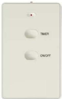
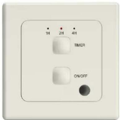
Wall Controller with remote control
This controller is a custom designed and manufactured controller for HEATSTRIP. It has been designed for ease of use to ensure economic running costs of your heater. It provides a timer for automatic heater operation.
The timer function has four settings. It can turn the heater on for 1 hour, 2 hours, 4 hours or constantly on.
The timer can be operated where it is installed or via remote control unit. It has pre set timing for 1 hour, 2 hours or hours or continuous, allowing the heater to operate continuously.
The remote control has a range of 10 metres and must be within line of sight of the wall switch.
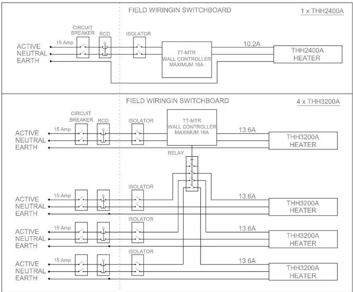
Controlling multiple units
It is possible to use one wall controller to control multiple heaters up to 16 Amps load. The wall controller is rated at 16 Amps and 220-240 volts. For larger current draw, it is recommended that you talk to your electrician who can use a relay to connect more units.
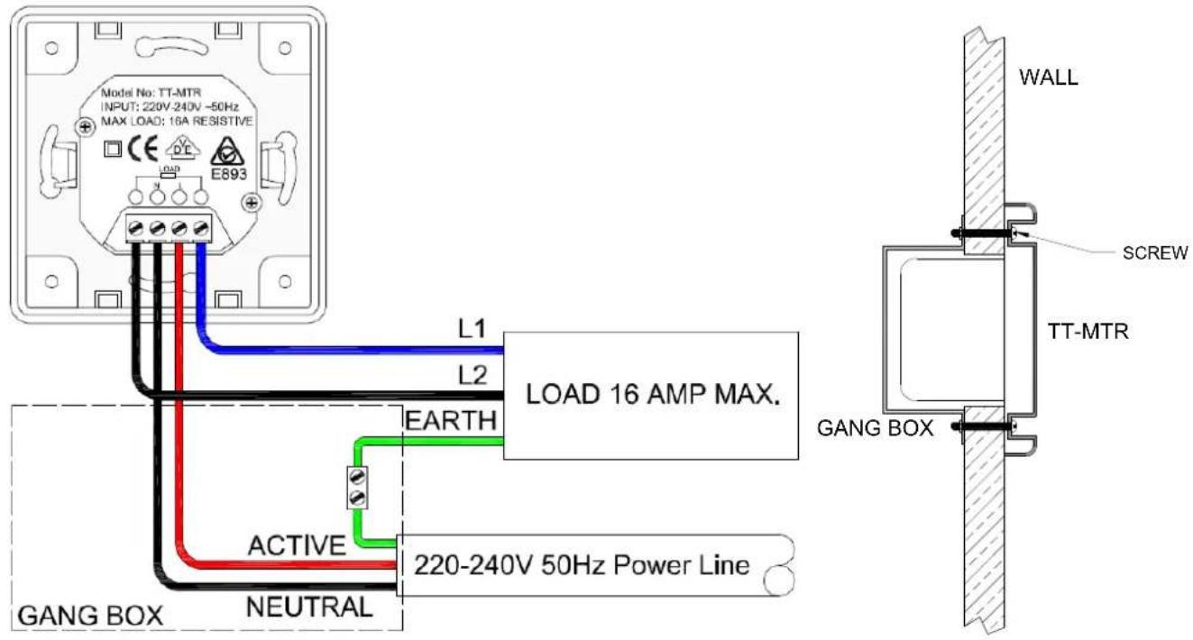
Mounting
The TT-MTR is designed to fit into a standard European wall gangbox. It will just as easily fit into a plaster wall. Your electrician can install this device.
The controller needs to be installed according to your local wiring guidelines.
Operation
Press "ON/OFF" button to turn power on and off.
Press "TIMER" button to set timer to 1, 2, 4 hours operation. The timer indicator light will show which time setting is selected. The timer will start the heater and automatically turn it off at the preselected time.
Safety
The TT-MTR controller must be installed in a dry location. It is not suitable for installation where rain or water could affect the unit..
Ensure the connections are properly connected.
This appliance is not intended for use by persons (including children) with reduced physical, sensory or intellectual capabilities, or lack of experience and knowledge, unless they have been given supervision or instruction concerning use of the appliance by a person responsible for their safety. Children should be supervised to ensure they do not play with the appliance.
Maintenance
The TT-MTR Controller is made from durable materials, however regular care and maintenance of your controller will help prolong the life of the product.
It is recommended that you dust the controller to keep the surface clean. The cleaning process at least every three months will reduce the amount of build up and keep it looking as best it can.
Do not use any abrasive materials or products to clean the controller, this includes solvents, citrus based cleaners or other harsh cleaning products. Do not use water or a damp cloth to clean the controller.
When handling the controller, ensure that your hands are clean or that you use clean gloves as grease or dirt can mark the surface of the controller.
| MODEL MAXIMUM VOLTAGE (Volts) | MAXIMUM CURRENT (Amps) | PACKAGED DIMENSIONS (mm) | WEIGHT (kg) | |
| TT-MTR 220- | 240 16 80 x 80 x 42 0.5 | |||
WALL CONTROLLER INSTALLATION GUIDE
Safety
HEATSTRIP Design has an IP rating of 55. This means it is safe for water ingress from all directions. The HEATSTRIP can be safely hosed down.
HEATSTRIP® has undergone extensive testing both in laboratory conditions; in Thermofil's manufacturing facility in Melbourne and field trials in Australia and overseas. It has been this testing that gives the purchaser the confidence of a high quality product.
Independent laboratory testing has confirmed Thermofil's full compliance with Australian and other International Standards. This includes CE, AS/ANZ, UL/CSE
The heater comes in both plug (1500W, 2400W) and hardwired (3200W) versions. In both cases the fixed wiring must be installed by a licensed electrician in accordance with the relevant wiring regulations.
HEATSTRIP® is Class 1 equipment and must be earthed.
In operation, this heater is VERY HOT—do not touch any part of the heater while it is turned on. Do not touch any part until 30 minutes after it is turned off.
This appliance is not intended for use by persons (including children) with reduced physical, sensory or intellectual capabilities, or lack of experience and knowledge, unless they have been given supervision or instruction concerning use of the appliance by a person responsible for their safety. Children should be supervised to ensure they do not play with the appliance.
Do not allow any cables, furnishings, flammable materials or other items come in contact with any surface of the heater.
If installed in wet areas, the heater switches or controls must be located so that they cannot be touched by persons in the bath or shower.
The heater needs to be installed as per the installation instructions paying special attention to the minimum clearances. The heater needs to be mounted on a rigid bracket or fixing.
The heater must not be mounted immediately below or in front of a socket outlet.
In case of a heater fault or damaged supply lead, the appliance should be returned to the point of purchase for return to Grand Hall Europe B.V. for repair.
Maintenance
The HEATSTRIP Design is made from durable materials, however regular care and maintenance of your heater will help prolong the life of the heater.
It is recommended that you hose down the heater and with a soft bristle brush, gently wipe the surfaces of the heater with a mild detergent to remove the built up contaminants from the environment. Then rinse all detergent off the heater. All chemicals in the atmosphere including cigarette smoke, pollution etc. will tarnish the surface of the heater. In this case, additional cleaning and maintenance may be required. The cleaning process undertaken at least every three months will reduce the amount of build up and keep it looking as best it can. If the heater is in a corrosive environment eg. salt spray, we recommend that you clean your heater with a light spray of fresh water every week. After cleaning, turn the heater on for 20 minutes to dry any water residue and prevent water staining.
Before cleaning or inspection activity, the heater must be switched off and cooled down completely. Do not use any abrasive materials or products to clean the heater, this includes solvents, citrus based cleaners or other harsh cleaning products.
When handling the heater, ensure that your hands are clean or that you use clean gloves as grease or dirt can mark the surface of the heater.
Do not use high pressure water to clean heaters, light water spray only.
Warranty Terms & Conditions
The below Warranty Terms and Conditions apply for international warranty only.
Grand Hall B.V. warrants to the original owner that HEATSTRIP Design products will be free from defects in materials and workmanship for a period of 12 months from the date of purchase in accordance with the following warranty terms and conditions.
Provision of this warranty is subject to:
- The HEATSTRIP® product must be installed in accordance with the Installation Instructions and relevant electrical standards and codes.
The HEATSTRIP® product must be maintained and cleaned according to instructions detailed in the Installation Manual. - There is no warranty expressed or implied with regard to capacity requirements. The selection of the unit or units depends entirely upon the system design and capacities as determined by the purchaser.
- The customer has not repaired, opened or altered the product in any unauthorised manner.
This warranty excludes damage to the product or components arising from circumstances outside the control of Grand Hall B.V., including, but not limited to, where the product is not used for intended purpose; where the product has been rectified in any way; incorrect installation; incorrect power supply; damaged caused during delivery; misapplication, misuse, abuse, vandalism, lack of maintenance or accident. - Grand Hall Europe's obligations under this warranty are limited to repair or replacement at Grand Hall Europe B.V. of any components of the product which Grand Hall Europe B.V. identifies to its satisfaction to be defective.
- Transportation charges involved in return of the product to Grand Hall Europe B.V. is the sole responsibility of the customer.
All products are inspected and tested before despatch and are at the risk of the purchaser after the shipment from Grand Hall Europe B.V., if not delivered by Grand Hall Europe B.V. to destination. - Discolouration of the surface may occur after a period of time, this does not constitute a warrantable event.
- Twisting and bending of the heaters may occur, this does not constitute a warrantable event.
No products or components will be supplied in advance of an examination of the faulty product or components by Grand Hall Europe B.V. or an authorized representative of Grand Hall Europe B.V. - Grand Hall Europe B.V. does not participate in any site related costs or labour expenses incidental to replacement of parts, repairing, removing, installing, servicing, transportation or handling of parts to complete products, and assumes no liability on parts repaired or replaced without written authorisation. Grand Hall Europe B.V. shall not be liable for any default or delay in performance of its warranty obligations caused by any circumstances beyond its control, including, but not limited to, judicial or government restrictions, strikes, fires, floods, abnormal weather conditions, delayed supply of components.
Should products be determined as damaged on arrival, immediately notify the transport company of the condition and have them noted on the freight documents. If damage is discovered after unpacking, demand immediate inspection by the transportation company and insist that a record of the damage is made on the freight documentation.
The customer warrants using the product in accordance with:
- Any instructions provided to it by Grand Hall Europe B.V. from time to time.
- All government and local regulations, including but not limited to all relevant electrical, environmental laws and regulations governing the installation, storage, use, handling and maintenance of the goods.
- All necessary and appropriate precautions and safety measures relating to the installation, storage, use, handling and maintenance of goods.
DISTRIBUTOR DETAILS FOR
EUROPE & UNITED KINGDOM
Distributed by: Manufactured by:
Grand Hall Europe B.V. Thermofilm Australia Pty. Ltd.
www.heatstrip.eu
27 Rosalie St
Springvale, Victoria, 3171 Australia
HEATSTRI
RADIANT OUTDOOR HEATERS
HANDLEIDING VOOR BEDIENING, INSTALLATIE EN ONDERHOUD
HEATSTRIP Design—EUROPA
De heater a ls de s i gn e n element!

Productverzicht
Ceiling Installation
Angled Ceiling Installation
Flush Mount Enclosure

| PART No “A” (mm) “B” (mm) “C” (mm) | |||
| THHAC-009 | 1030 | 974 | 970 |
| THHAC-011 | 1470 | 1414 | 1410 |
| THHAC-012 | 1880 | 1824 | 1820 |
| SUITABLE FOR MODELS | PART No | HOLE CUTOUT DIMENSIONS (mm) | OVERALL DIMENSIONS (mm) | WEIGHT (kg) | |
| THH1500AEU | THHAC-009 | 9 | 80 x 230 | 1030 x 280 x 125 | 5.5 |
| THH2400AEU | THHAC-011 | 1420 x | 230 | 1470 x 280 x 125 | 8 |
| THH3200AEU | THHAC-012 | 1830 x | 230 | 1880 x 280 x 125 | 9 |
Installatie-afstanden Flush Mount Enclosure
End-to-end montagebeugel
| PART No | PACKAGED DIMENSIONS (mm) | WEIGHT (kg) | MATERIALS | NOTES |
| THHAC-004 | 150 x 150 x 50 1 316 SS | Brackets only (for use with 25x25x1mm tube) | ||
| THHAC-005 | 300 x 150 x 50 2 316 SS | Kit includes 2x300mm extension pole, screws and brackets | ||
| THHAC-006 | 600 x 150 x 50 2 316 SS | Kit includes 2x600mm extension pole, screws and brackets | ||
| THHAC-007 | 900 x 150 x 50 2.5 | 316 SS | Kit includes 2x900mm extension pole, screws and brackets | |
| THHAC-008 | 1200 x 150 x 50 3 316 SS | Kit includes 2x1200mm extension pole, screws and brackets |
Veiligheid
APPLICATION THX THH THS

Ceiling Installation
Angled Ceiling Installation
HEATSTRIP

Options de fixation
Flush Mount Enclosure


| PART No “A” (mm) “B” (mm) “C” (mm) | |||
| THHAC-009 | 1030 974 | 970 | |
| THHAC-011 | 1470 1414 | 1410 | |
| THHAC-012 | 1880 1824 | 1820 | |
| SUITABLE FOR MODELS | PART No | HOLE CUTOUT DIMENSIONS (mm) | OVERALL DIMENSIONS (mm) | WEIGHT (kg) | |
| THH1500AEU | THHAC-009 | 9 | 80 x 230 | 1030 x 280 x 125 | 5.5 |
| THH2400AEU | THHAC-011 | 1420 x | 230 | 1470 x 280 x 125 | 8 |
| THH3200AEU | THHAC-012 | 1830 x | 230 | 1880 x 280 x 125 | 9 |
| PART No | PACKAGED DIMENSIONS (mm) | WEIGHT (kg) | MATERIALS | NOTES |
| THHAC-004 | 150 x 150 x 50 1 316 SS | Brackets only (for use with 25x25x1mm tube) | ||
| THHAC-005 | 300 x 150 x 50 2 316 SS | Kit includes 2x300mm extension pole, screws and brackets | ||
| THHAC-006 | 600 x 150 x 50 2 316 SS | Kit includes 2x600mm extension pole, screws and brackets | ||
| THHAC-007 | 900 x 150 x 50 2.5 | 316 SS | Kit includes 2x900mm extension pole, screws and brackets | |
| THHAC-008 | 1200 x 150 x 50 3 316 SS | Kit includes 2x1200mm extension pole, screws and brackets |
Sécurité
Grand Hall Europe B.V. Thermofil Australia Pty Ltd
www.heatstrip.eu
27 Rosalie St
Springvale, Victoria, 3171, Australia
HEATSTRI
RADIANT OUTDOOR HEATERS
Ceiling Installation
Angled Ceiling Installation

Flush Mount Enclosure


| PART No “A” (mm) “B” (mm) “C” (mm) | |||
| THHAC-009 | 1030 974 | 970 | |
| THHAC-011 | 1470 1414 | 1410 | |
| THHAC-012 | 1880 1824 | 1820 | |

| SUITABLE FOR MODELS | PART No | HOLE CUTOUT DIMENSIONS (mm) | OVERALL DIMENSIONS (mm) | WEIGHT (kg) | |
| THH1500AEU | THHAC-009 | 9 | 80 x 230 | 1030 x 280 x 125 | 5.5 |
| THH2400AEU | THHAC-011 | 1420 x | 230 | 1470 x 280 x 125 | 8 |
| THH3200AEU | THHAC-012 | 1830 x | 230 | 1880 x 280 x 125 | 9 |
Grand Hall Europe B.V.
Thermofil Australia Pty Ltd
www.heatstrip.eu
27 Rosalie St
Springvale, Victoria, 3171 Australia