
IH 478 P - Cooker PROLINE - Free user manual and instructions
Find the device manual for free IH 478 P PROLINE in PDF.
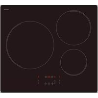
| Product type | Ceramic glass induction hob |
| Brand | Proline |
| Model | IH 478 P |
| Number of cooking zones | 4 |
| Total power | 7100 W |
| Power of cooking zones (nominal / booster) | Front left: 1400 W / 2000 W; Rear left: 1400 W; Rear right: 2300 W / 3000 W; Front right: 1400 W |
| Cooking zone diameters | Front left: 180 mm; Rear left: 170 mm; Rear right: 220 mm; Front right: 145 mm |
| Booster function | Yes (on 2 cooking zones, duration 5 minutes) |
| Programmable timer | Yes (0 to 99 minutes, per cooking zone) |
| Control panel lock | Yes |
| Pan detection | Yes |
| Residual heat indicator | Yes (symbol H) |
| Control type | Touch controls |
| Display | Digital (levels 0-9, P, E, U, H, L) |
| Power supply | 220-240 V~ 50/60 Hz (single-phase) or 400 V~ 2P+N (two-phase) |
| Maximum power consumption | 7100 W |
| Recommended protection rating | 25 A (single-phase) or 16 A (two-phase) |
| Power cable | H05VV-F or H05RR-F, section 3x2.5 mm² or 4x1.5 mm² |
| Ventilation | Automatic |
| Surface material | Ceramic glass |
| Maintenance | Clean with soapy water or special ceramic glass cleaner. Do not use steam or abrasives. |
| Safety | Child lock, automatic shut-off, pan detection, residual heat indicator |
| Weight (estimated) | Approximately 10 kg |
| Dimensions (estimated) | Approximately 590 x 520 mm (check the manual) |
| Repairs | Only to be carried out by qualified personnel |
Frequently Asked Questions - IH 478 P PROLINE
User questions about IH 478 P PROLINE
0 question about this device. Answer the ones you know or ask your own.
Ask a new question about this device
Download the instructions for your Cooker in PDF format for free! Find your manual IH 478 P - PROLINE and take your electronic device back in hand. On this page are published all the documents necessary for the use of your device. IH 478 P by PROLINE.
USER MANUAL IH 478 P PROLINE
PROLINE
TABLE A INDUCTION
MODELE IH478P
Chère cliente, cher client,
natural_image
Illustration of three frying panes with no stopper and sad face emojis, no text or symbols presentPROLINE
INDUCTION KOOKPLAAT
MODEL IH478P

GEBRUIKSHANDLEIDING
Geachte Klant,
ANDERE BESCHERMINGEN....20
BESCHRIJVING VAN HET APPARAAT....21
IN WERKING STELLEN....22
VOOR HET EERSTE GEBRUIK....22
PRINCIPE VAN INDUCTIE 22
TIPTOETSEN 22
INWERKINGSTELLING....23
DETECTIE VAN DE PAN....23
AANDUIDING RESTWARMTE....23
BOOSTER FUNCTIE 23
TIMER FUNCTIE 24
VERGRENDELING VAN HET BEDIENINGSPANEEL....25
KOOKADVIES....26
BESCHRIJVING VAN HET APPARAAT
4 × [0]
geen of [H]
[0]
[1] tot [9]
[9] tot [1]
[0] of [H]
natural_image
Illustration of three frying panes with no stop sign, each accompanied by a sad face emoji (no text or symbols)PROLINE
INDUCTION HOB
MODEL IH478P
INSTRUCTIONS
Dear customer,
Thank you for having chosen our induction ceramic hob. In order to make the best use of your appliance, we would advise you to read carefully the following notes and to keep them for future consultation.
SUMMARY
IMPORTANT SAFETY INSTRUCTIONS....34
WARNINGS....35
SPECIFICATIONS & CONTROL PANEL....36
TECHNICAL CHARACTERISTICS....36
CONTROL PANEL 36
APPLIANCE DESCRIPTION....37
DISPLAY 37
VENTILATION....37
USING THE HOB....37
BEFORE FIRST USE....37
INDUCTION PRINCIPLE....37
SENSITIVE TOUCH....37
STARTING-UP 38
PAN DETECTION 38
RESIDUAL HEAT INDICATION....38
BOOSTER FUNCTION 38
TIMER....39
CONTROL PANEL LOCKING....39
COOKING ADVICES....40
PAN QUALITY....40
PAN DIMENSION....40
EXAMPLES OF COOKING POWER SETTING....41
MAINTENANCE AND CLEANING 41
TROUBLESHOOTER....42
INSTALLATION INSTRUCTIONS....43
ADVICE FOR THE INSTALLER 43
INSTALLATION 43
ELECTRICAL CONNECTION 45
CAUTIONS......45
CONNECTION TO POWER SUPPLY 46
IMPORTANT SAFETY INSTRUCTIONS
- Unpack all the materials.
- The installation and connecting of the appliance have to be done by approved specialists. The manufacturer can not be responsible for damage caused by building-in or connecting the appliance incorrectly.
- To be used, the appliance must be well-equipped and installed in a kitchen unit and an adapted and approved work surface.
- Remove all labels and self-adhesives from the ceramic glass.
- Do not change or alter the appliance.
- The cooking plate can not be used as freestanding or as working surface.
- The appliance must be grounded and connected conforming to local standards.
- Do not use any extension cable to connect it.
- The appliance can not be used above a dishwasher or a tumble-dryer: steam may damage the electronic appliances.
- Switch the heating zones off after use.
- Keep an eye on the cooking using grease or oils: that may quickly ignite.
- Be careful not to burn yourself while or after using the appliance.
- Make sure no cable of any fixed or moving appliance contacts with the glass or the hot saucepan.
- Objects such as credit cards, floppy disks, calculators should not be placed near to the appliance.
- Never cover the appliance with a cloth or a protection sheet. This could catch fire.
- Rough pan bottoms or damaged saucepans (not enamelled cast iron pots,) may damage the ceramic glass.
- Sand or other abrasive materials may damage ceramic glass.
- Avoid dropping objects, even little ones, on the vitroceramic surface.
- Do not hit the edges of the glass with saucepans.
- Make sure that the ventilation of the appliance complies with to the manufacturer's instructions.
- Do not put or leave empty saucepans on the vitroceramic hobs.
- Sugar, synthetic materials or aluminium sheets must not contact with the heating zones. These may cause breaks or other alterations of the vitroceramic glass by cooling: switch on the appliance and take them immediately out of the hot heating zone (be careful: do not burn yourself).
- Never place any hot container over the control panel.
- If a drawer is situated under the built in appliance, make sure the space between the content of the drawer and the inferior part of the appliance is large enough (2 cm). This is essential to ensure a correct ventilation.
- Never put any inflammable object (e.g. sprays) into the drawer situated under the vitroceramic hob. The eventual cutlery drawers must be resistant to heat.
- If a defect is noticed, switch off the appliance and turn off the electrical supply.
- If the ceramic glass is cracked or fissured, you must unplug the appliance and contact the after sales service.
• Repairs must be done by specialists. Do not open the appliance yourself. - Make sure that the saucepan always centred on the cooking zone. The bottom of the pan must cover as much as possible of the cooking zone.
- For the users of pacemaker, the magnetic field could interfere with its operating. We recommend getting information from the retailer or from the doctor.
- Do not use aluminium or synthetic material containers: they could melt on hot cooking zones.
WARNINGS
- This appliance can be used by children aged from 8 years and above and persons with reduced physical, sensory or mental capabilities or lack of experience and knowledge if they have been given supervision or instruction concerning use of the appliance in a safe way and understand the hazards involved. Children shall not play with the appliance. Cleaning and user maintenance shall not be made by children without supervision.
- WARNING: Unattended cooking on a hob with fat or oil can be dangerous and may result in fire. NEVER try to extinguish a fire with water, but switch off the appliance and then cover flame e.g. with a lid or a fire blanket.
- WARNING: Danger of fire: do not store items on the cooking surface.
- WARNING: If the surface is cracked, switch off the appliance to avoid the possibility of electric shock.
- Metallic objects such as knives, forks, spoons and lids should not be placed on the hob surface since they can get hot.
- The appliance is not intended to be operated by means of an external timer or separate remote-control system.
- Do not use a steam cleaner.

THE USE OF EITHER POOR QUALITY POT OR ANY INDUCTION ADAPTOR PLATE FOR NON-MAGNETIC COOKWARE RESULTS IN A WARRANTY BREACH. IN THIS CASE, THE MANUFACTURER CANNOT BE HELD RESPONSIBLE FOR ANY DAMAGE CAUSED TO THE HOB AND/OR ITS ENVIRONMENT.

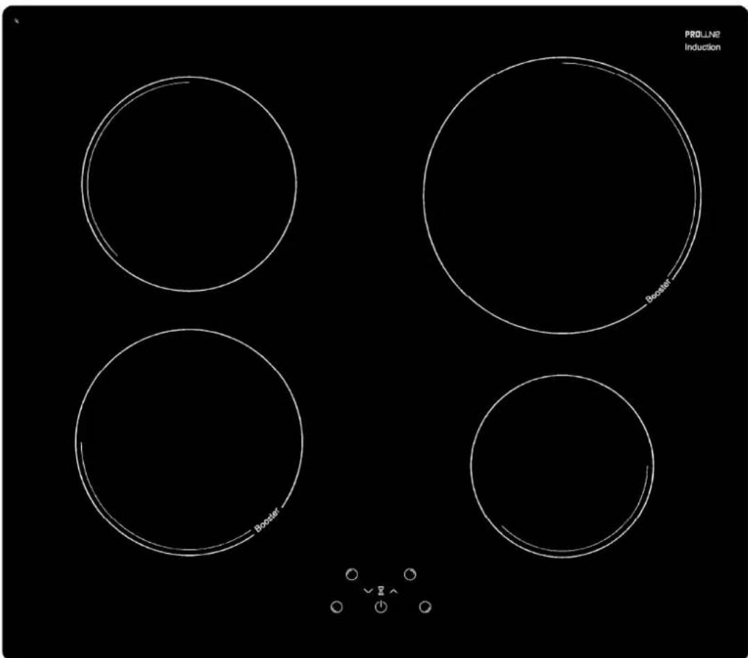
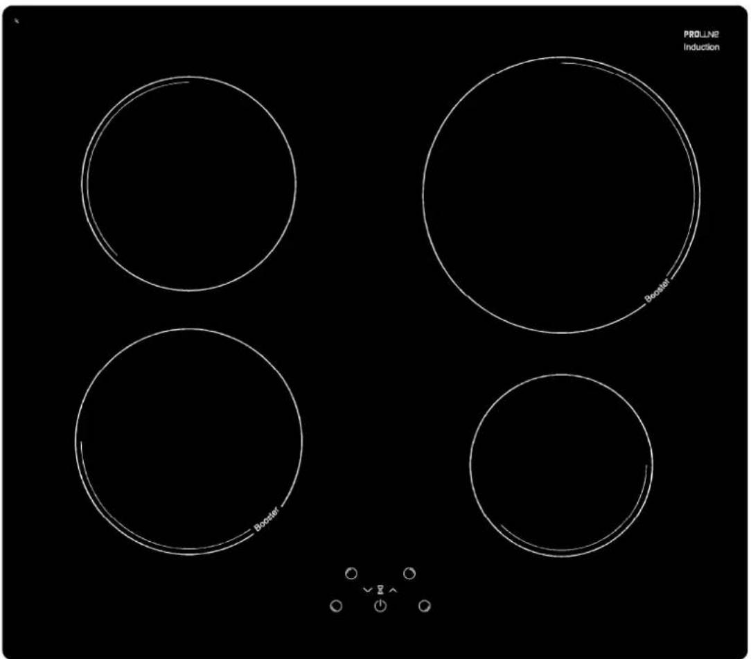
SPECIFICATIONS & CONTROL PANEL
Technical characteristics
| Total Power | Position of the heating zone | Diameter | Nominal Power* | Booster Power* | Minimum diameter detection |
| 7100 W | Front left | 180 mm | 1400 W | 2000 W | 90 mm |
| Rear left | 170 mm | 1400 W | - | 90 mm | |
| Rear right | 220 mm | 2300 W | 3000 W | 100 mm | |
| Front right | 145 mm | 1400 W | - | 90 mm |
* The given power may change according to the dimensions and material of the pan
Control panel
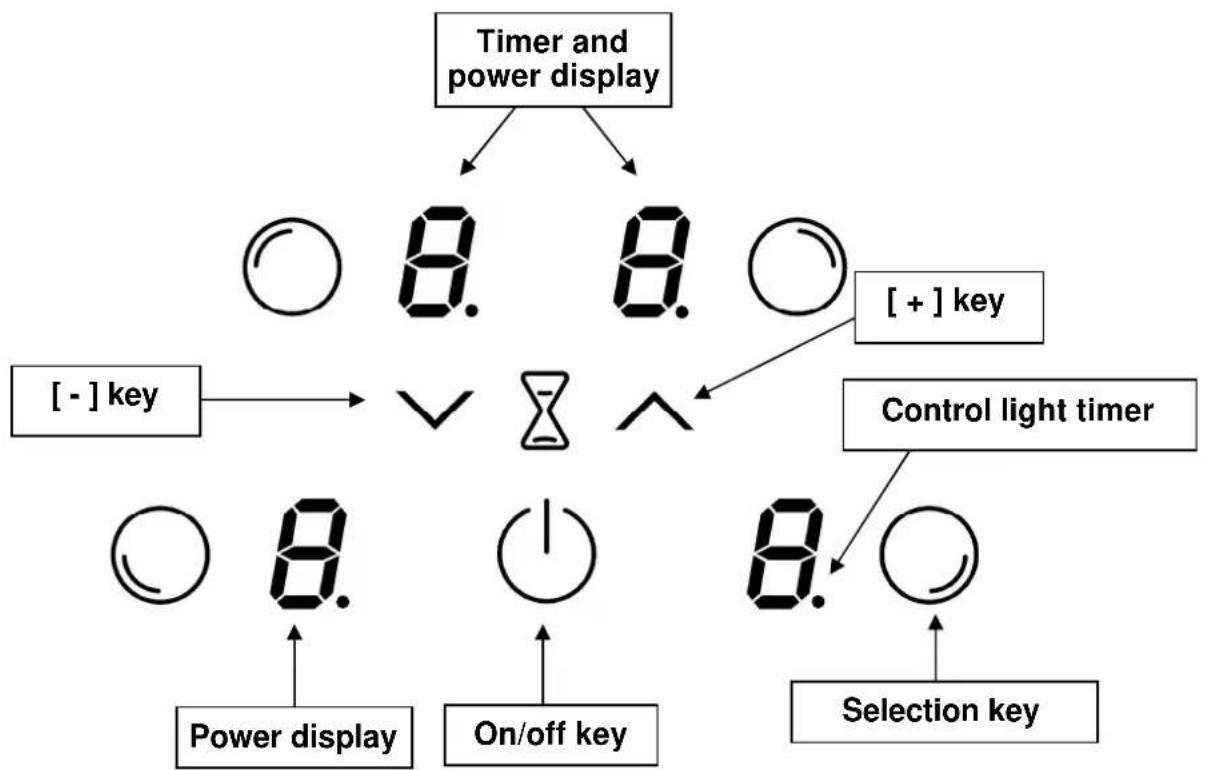
flowchart
graph TD
    A["Timer and power display"] --> B["○ 8. 8. ○"]
    A --> C["+-"] key --> D["∨"]
    D --> E["○"]
    E --> F["Power display"]
    E --> G["On/off key"]
    E --> H["Selection key"]
    I["+"] key --> J["○"]
    J --> K["Control light timer"]
    L["○"] --> M["Power display"]
    N["○"] --> O["On/off key"]
    P["○"] --> Q["Selection key"]
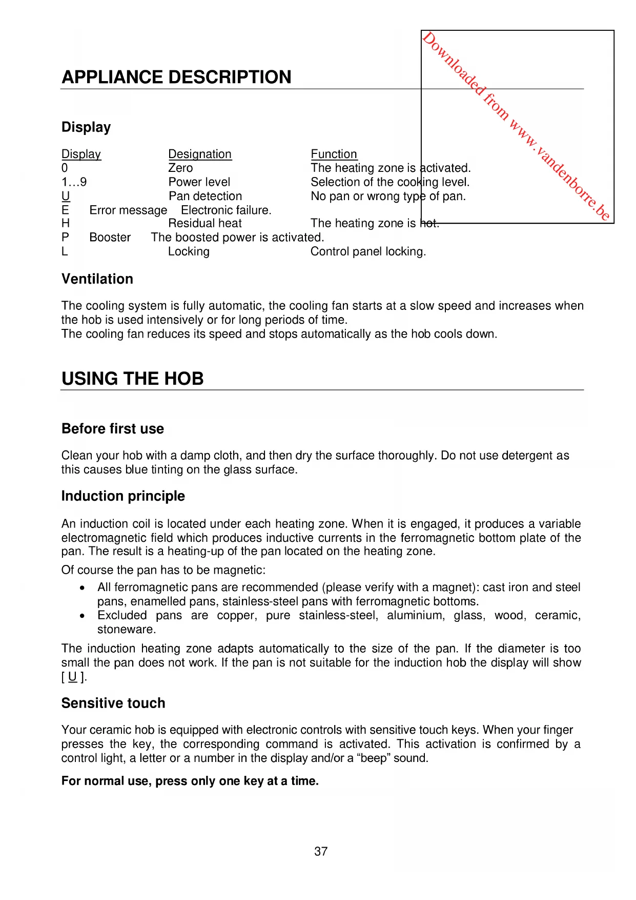
APPLIANCE DESCRIPTION
Display
| Display | Designation | Function | |
| 0 | Zero | The heating zone is activated. | |
| 1...9 | Power level | Selection of the cooking level. | |
| U | Pan detection | No pan or wrong type of pan. | |
| E | Error message | Electronic failure. | |
| H | Residual heat | The heating zone is hot. | |
| P | Booster | The boosted power is activated. | |
| L | Locking | Control panel locking. | |
Ventilation
The cooling system is fully automatic, the cooling fan starts at a slow speed and increases when the hob is used intensively or for long periods of time.
The cooling fan reduces its speed and stops automatically as the hob cools down.
USING THE HOB
Before first use
Clean your hob with a damp cloth, and then dry the surface thoroughly. Do not use detergent as this causes blue tinting on the glass surface.
Induction principle
An induction coil is located under each heating zone. When it is engaged, it produces a variable electromagnetic field which produces inductive currents in the ferromagnetic bottom plate of the pan. The result is a heating-up of the pan located on the heating zone.
Of course the pan has to be magnetic:
- All ferromagnetic pans are recommended (please verify with a magnet): cast iron and steel pans, enamelled pans, stainless-steel pans with ferromagnetic bottoms.
- Excluded pans are copper, pure stainless-steel, aluminium, glass, wood, ceramic, stoneware.
The induction heating zone adapts automatically to the size of the pan. If the diameter is too small the pan does not work. If the pan is not suitable for the induction hob the display will show [] .
Sensitive touch
Your ceramic hob is equipped with electronic controls with sensitive touch keys. When your finger presses the key, the corresponding command is activated. This activation is confirmed by a control light, a letter or a number in the display and/or a “beep” sound.
For normal use, press only one key at a time.
Starting-up
You must first switch on the hob, then the heating zone:
• Start-up/ switch off the hob:
| Action | Control panel | Display |
| To start | Press key [1] | |
| Touch the key | Press key [1] |
• Start-up/ switch off a heating zone:
| Action Control panel | Display | |
| Zone selection | Press selection key from the zone | [0] |
| Increase power | Press key [+] | [1] to [9] |
| Decrease power | Press key [-] | [9] to [1] |
| Stop | Press key [-] | [0] or [H] |
If no action is made within 20 second the hob returns to waiting state.
![Downloaded from www.vandenborre.be 4 x [0] Nothing or [H]](/content/2026/02/395287/images/7050ee492ec5f4dd62c72e4aee9b29aba0060d01fd0b093bf5c6e34f4d0e7a8f.jpg)
Pan detection
The pan detection ensures perfect safety. The induction doesn't work:
- If there is no pan on the heating zone or if this pan is not suited to induction cooking it is impossible to increase the power and the display shows [ ] This symbol disappears when a suitable pan is placed on the heating zone.
- If the pan is removed from the heating zone the operation is stopped. The display shows [U]. The symbol [U] disappears when the pan is put back onto the heating zone. The cooking continues with the power level initially set.
After use, switch the heat element off: don't let the pan detection [U] activate.
Residual heat indication
After switching off the hob, the heating zones are still hot and indicates [H] on the display. The symbol [H] disappears when the heating zones may be touched without danger. While the residual heat indicators are lit, do not touch the heating zones and don't put any heat sensitive object on them. There are risks of burns and fire.
Booster function
The booster function [P] grants a boost of power to the front left zone or right zone only. If this function is activated the heating zones works for 5 minutes with an ultra high power. To start the boost function, repeatedly press the [+] button until [P] appears in the display.
- Start up / Stop the booster function:
| Action Control panel | Display | |
| Zone selection | Press selection key from the zone | [0] |
| Increase power | Press key [+] | [1] to [9] |
| Start up the booster | Press key [+] | [P] during 5 min |
| Stop the booster | Press key [-] | [9] |
• Power management:
The whole cooking hob is equipped by a maximum of power. When the booster function is activated, and not to exceed the maximum power, the electronic system orders to reduce automatically the power level of an other heating zone. The display is blinking on [9] during a few seconds and then shows the maximum of power allowed:
| Heating zone selected [P] is displayed | The other heating zone: [9] goes to [7] | (example: power level 9) |
Timer
The timer is able to be used simultaneously with both heating settings (from 0 to 99 minutes) for each heating zone.
zones and with different time
- Setting and modification of the cooking time :
| Action | Control panel | Display |
| Zone selection | Press selection key from the zone | |
| Increase power | Press key [ + ] | |
| To select « Timer » | Press simultaneously [ - ] and [ + ] | |
| Decrease the time | Press key [ - ] | |
| Increase the time | Press key [ + ] | |
| [0] |
| [1] ... [9] [P] |
| [00] |
| [00] wents to 30,29 |
| time increase |
After a few seconds the control light stops blinking.
The time is confirmed and the cooking starts until the time reaches [00].
• To stop the cooking time :
| Action | Control panel | Display | |
| Zone selection | Press selection key from the zone | [0] | |
| To select « Timer » | Press simultaneously [ - ] and [ + ] | The remaining time | |
| To stop the « Timer » | Press key [ - ] | [00] then stops | |
If several timers are activated repeat the process.
• Automatic stop at the end of the cooking time :
As soon as the selected cooking time is finished the timer displays blinking [00] and a sound rings. To stop the sound and the blinking press any key.
- Egg timer function :
| Action Control panel | Display | |
| Activate the hob | Press key [1] | [0] or [H] |
| Select« Timer » | Press simultaneously [-] and [+] | [00] |
| Decrease the time | Press key [-] | [00] wents to 30,29.... |
| Increase the time | Press key [+] | time increase |
After a few seconds the control light stops blinking.
As soon as the selected cooking time is finished the timer displays blinking [00] and a sound rings.
To stop the sound and the blinking press any key.
Control panel locking
To avoid modifying a setting of cooking zones when cleaning, the control panel can be locked (excluding the On/Off key [ ①]).
- Locking :
| Action | Control panel | Display | |
| Start | Press key [1] | [0] or [H] | |
| Hob locking | Press simultaneously [-] and selection key from the front zone | [0] or [H] | |
| Repress selection key from the | 4 x [L] | ||
| front zone |
- Unlocking :
| Action Start | Control panel | Display | 4 x [L] |
| Press key [1] | |||
| In the 5 seconds after start: | |||
| Unlocking the hob | Press simultaneously [- ] and selection key from the front zone | 4 x [L] | |
| Repress key [- ] | No light on the displays | ||
COOKING ADVICES
Pan quality
Compatible materials: steel, enamelled steel, cast iron, ferromagnetic stainless-steel, aluminium with ferromagnetic bottom.
Non compatible materials: aluminium and stainless-steel without ferromagnetic bottom, copper, brass, glass, ceramic, porcelain.
The manufacturers specify if their products are compatible with induction appliances. To check if pans are compatible:
- Put a little water in a pan placed on an induction heating zone set at level [9]. This water must heat in a few seconds.
• A magnet sticks on the bottom of the pan.
Certain pans can make noise when they are placed on an induction cooking zone. This noise doesn't mean any failure on the appliance and doesn't influence the cooking operating.
natural_image
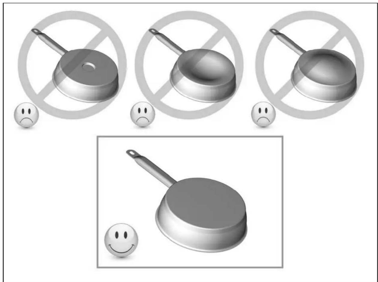
Illustration of frying panes and a frying pan with no-smoking symbols, accompanied by sad face emojis (no text or labels)Pan dimension
The cooking zones are, up to a limit, automatically adapted to the diameter of the pan. However the bottom of this pan must have a minimum of diameter according to the corresponding cooking zone. To obtain the best efficiency of your hob, please place the pan in the centre of the cooking zone.
Examples of cooking power setting
| 1 to 2 Melting | Reheating | Sauces, butter, chocolate, gelatineDishes prepared beforehand |
| 2 to 3 Simmering | Defrosting | Rice, pudding, sugar syrupDried vegetables, fish, frozen products |
| 3 to 4 | Steam | Vegetables, fish, meat |
| 4 to 5 | Water | Steamed potatoes, soups, pasta,fresh vegetables |
| 6 to 7 Medium cooking | Simmering | Meat, liver, eggs, sausagesGoulash, roulade, tripe |
| 7 to 8 Cooking Potatoes, fritters, wafers | ||
| 9 Frying, roosting, boiling water | Steaks, omelettes, fried dishes, water | |
| P Frying, roosting | Boiling water | scallops, steaksBoiling significant quantities of water |
MAINTENANCE AND CLEANING
Switch-off the appliance before cleaning.
Do not clean the hob if the glass is too hot risk of burns.
- Remove light marks with a damp cloth.
- Highly corrosive or abrasive detergents and cleaning equipment likely to cause scratches must be avoided.
- Do not ever use a steam-cleaner.
- Do not use any object that may scratch the ceramic glass.
- Ensure that the pan is dry and clean. Ensure that there are no grains of dust on your ceramic hob or on the pan. Sliding rough saucepans will scratch the surface.
- Spillages of sugar, jam, jelly, etc. must be removed immediately to prevent the surface being damaged.
When the symbol [ E 4 ] appears:
I) The table must be reconfigured. Please implement the following steps: Important: before you start:
• make sure there are no pots on the hob
• take a pot with a ferromagnetic bottom and a minimum diameter of 16 cm
- disconnect the appliance from the grid by removing the fuse or turning the circuit breaker off
- start the procedure within 2 minutes after reconnecting the hop to the grid
- reconnect the hob to the grid
- don't use the [0/l] touch
II) First step: cancel the existing configuration
1) Press [-] and hold down
2) With your other hand, press successively and quickly (less than 2s) on each [O] key.
Begin from the front right side and turn contrary clockwise, as described on the picture (from a to d).
![PROLINE IH 478 P - When the symbol [ E 4 ] appears: - 1](/content/2026/02/395287/images/45b625edec6c3bb52729f2891f05030efcdc5588140e3818bab1f16f475ab969.jpg)
flowchart
graph TD
    A["Start"] --> B["Car 1"]
    B --> C["Car 2"]
    C --> D["Car 3"]
    D --> E["Car 4"]
    E --> F["Car 5"]
    F --> G["Car 6"]
    G --> H["Car 7"]
    H --> I["Car 8"]
    I --> J["Car 9"]
    J --> K["Car 10"]
    K --> L["Car 11"]
    L --> M["Car 12"]
    M --> N["Car 13"]
    N --> O["Car 14"]
    O --> P["Car 15"]
    P --> Q["Car 16"]
    Q --> R["Car 17"]
    R --> S["Car 18"]
    S --> T["Car 19"]
    T --> U["Car 20"]
    U --> V["Car 21"]
    V --> W["Car 22"]
    W --> X["Car 23"]
    X --> Y["Car 24"]
    Y --> Z["Car 25"]
    Z --> AA["Car 26"]
    AA --> AB["Car 27"]
    AB --> AC["Car 28"]
    AC --> AD["Car 29"]
    AD --> AE["Car 30"]
    AE --> AF["Car 31"]
    AF --> AG["Car 32"]
    AG --> AH["Car 33"]
    AH --> AI["Car 34"]
    AI --> AJ["Car 35"]
    AJ --> AK["Car 36"]
    AK --> AL["Car 37"]
    AL --> AM["Car 38"]
    AM --> AN["Car 39"]
    AN --> AO["Car 40"]
    AO --> AP["Car 41"]
    AP --> AQ["Car 42"]
    AQ --> AR["Car 43"]
    AR --> AS["Car 44"]
    AS --> AT["Car 45"]
    AT --> AU["Car 46"]
    AU --> AV["Car 47"]
    AV --> AW["Car 48"]
    AW --> AX["Car 49"]
    AX --> AY["Car 50"]
A double "beep" means an error occurred. If so, start again from item 1).
3) Remove your fingers from the touch control, press simultaneously [ + ] and [ - ] for a few seconds, until blinking [ E ] symbols appear.
4) Wait until [E] symbols stops blinking.
5) After few seconds, [E] are automatically transformed in [C]. The existing setup has been cancelled.
Note: For induction hobs with 3 cooking zones, The rear right zone (b) doesn't exist, so push 2 times on the front right zone (a) that means (a → a → c → d).
III) Second step: new setup
1) Take a ferromagnetical pot with a minimum diameter of 16 cm
2) Select a cooking zone by pushing on the corresponding [O] key
3) Place the pot on the area to be set
4) Wait until the [ C ] display becomes a [- ]. The selected zone is now configured.
5) Follow the same procedure for each cooking zone with a [ C ] display.
6) All the cooking zones are configured once all the displays are turned off.
Please use the same pot for the whole procedure.
Never put several pots together on the zones during the setup-process.
- If [ E 4 ] displaying remains, please call the customer care
The hob or the cooking zone doesn't start-up:
- The hob is badly connected to the electrical supply.
• The protection circuit has tripped. - The locking function is activated.
- The sensitive keys are covered with grease or water.
- An object is put on a key.
The control panel displays [U]:
- There is no pan on the cooking zone.
- The pan is not compatible with induction appliances.
• The diameter of the pan is too small.
The control panel displays or [E]:
- Disconnect and reconnect the hob.
- Call the After-sales Service.
One or all cooking zone cut-off:
• The safety system triggered.
• You forgot to turn off the hob.
• One or more touch keys are covered.
• The pan is empty and its bottom overheated.
- The hob also has an automatic reduction of power level when the hob experiences overheating
Continuous ventilation after cutting off the hob:
• This is not a failure, the fan continues to protect the electronic device.
• The fan cooling stops automatically.
The control panel displays [L]:
• Refer to the chapter: Control Locking on page 24.
INSTALLATION INSTRUCTIONS
Advice for the installer
IMPORTANT
Appliance installation and maintenance must only be carried out by QUALIFIED TECHNICIANS and in compliance with the local safety standards.
Failure to observe this rule will invalidate the warranty
Installation
How to fit the gasket:
The gasket supplied with the hob avoids all infiltration of liquids in the cabinet. This installation has to be done carefully, in conformity with the following drawing.
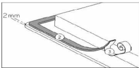
Stick the gasket (2) two millimeters from the external edge of the glass, after removing the protection sheet (3).
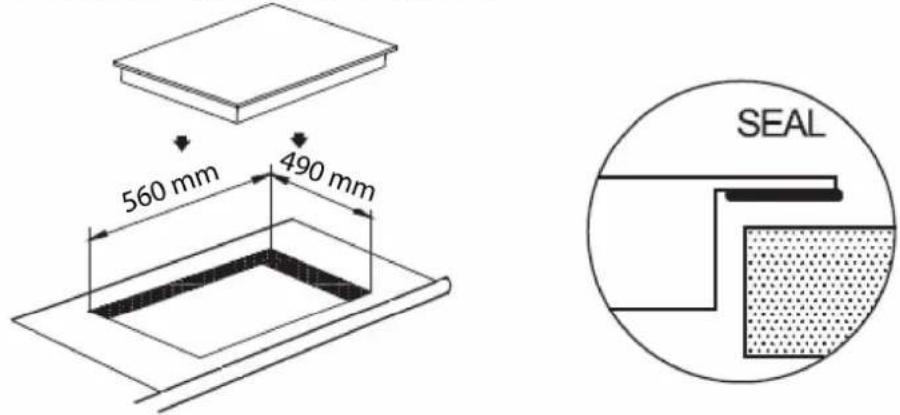
Fitting - installing:
- Cut a hole in the worktop of the dimension shown in the diagram below. Ensure that there is a distance of 50 mm between the hob and the wall or sides. The worktop should be at least 30 mm thick and of heat-resistant material.
- The hobs are classified as "Y" class for heat protection. Ideally the hob should be installed with plenty of space on either side. There may be a wall at the rear and tall units or a wall at one side. On the other side, however, no unit or divider must stand higher than the hob.
- The piece of furniture or the support in which the hob is to be furniture, the laminate coatings and the glue used to fix temperatures of up to 100 °C.
- The mural rods of edge must be heat-resisting.
- Do not install the hob above a unventilated oven.
- To ensure a good air circulation, allow a space of 20mm casing.
lly the hob should be installed ear and tall units or a wall r must stand higher than
fitted, as well as the edges of them, must be able to resist
under the bottom of the hob
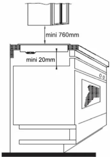
- Warning: For the safety gap between the hob and the cooker hood consult the instructions supplied by the hood manufacturer. In case of absence of instructions a distance minimum of 760 mm is recommended.
- If a drawer is located under the hob, do not store flammable (e.g. aerosol sprays) or non heat-resistant items inside.
- Materials which are often used to make worktops expand on contact with water. To protect the cut out edge, apply a coat of varnish or special sealant. Particular care must be given to applying the adhesive joint supplied with the hob to prevent any leakage into the supporting furniture. This gasket guarantees a correct seal when used in conjunction with smooth work top surfaces.
- The connection cord should be secured after building, with no mechanical constraint, for example example: a drawer.
ELECTRICAL CONNECTION
Installation must be carried out according to the manufacturer's inst may cause harm and damage to people, animals or property, for wh no responsibility.
structions. Incorrect installation which the manufacturer accepts
Before carrying out any work on the electrical section of the appliance from the mains.
ce, it must be disconnected
Connection to a good earth wiring system is absolutely essential.
The manufacturer accepts no responsibility for any inconvenience caused by failure to comply with this rule.
The hob must be installed by a qualified electrician in line with all electrical and installation requirements published by the Institute of Electrical Engineers. We recommend that the appliance is connected by a qualified electrician, who is a member of the N.I.C.E I C. and who will comply with the I.E.E. and local regulations.
Before carrying out the connection to the power supply, the voltage rating of the appliance (stamped on the appliance identification plate) must be checked for correspondence to the available mains supply voltage, and the mains electric wiring should be capable of handling the appliance's power rating (also indicated on the identification plate).
This appliance must be connected by a competent person, using fixed wiring via a DOUBLE POLE SWITCHED FUSED SPUR OUTLET (with 3 mm minimum distance between the contacts).
A double pole switch must be provided no further than 2 metres from the appliance to the electrical supply. All supply current and earth conductors must be able to withstand an ambient temperature of 75^ C.
After having installed the appliance, the power switch must always be in a accessible position. Use a 35 AMP fuse
Cautions
- The induction hob must be installed by a properly qualified person. Never try to install the appliance yourself.
- The induction hob must not be installed above refrigerators, freezers, dishwashers or tumble dryers. Install the induction hob away from heat sources such as ovens or direct sunlight.
- The induction hob should be installed so that optimum radiation of heat is possible.
- The wall and the area above the hob should be able to withstand heat.
• To avoid any damage, the sandwich layer and adhesive should be heat-resistant.
Connection to power supply
The socket should be connected in compliance with the relevant standard, to a dedicated omnipolar circuit breaker. 30 A minimum supply.
Monophase 230V\~1P+N
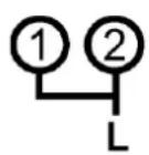

1P+N
Put a bridge between terminal 1 and 2
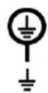
Attach the green/yellow wire to the terminal Earth
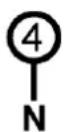
The neutral N to the terminal 4
The phase L to one of the terminal 1 or 2
Biphase 400V\~ 2P+N
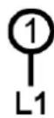
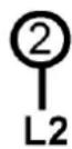

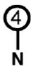

2P+N
Put a bridge between terminal 1 and 2
Attach the green/yellow wire to the terminal Earth
The neutral N to the terminal 4
The phase L1 to the terminal 1 and the phase L2 to the terminal 2
| Mains | Connection | Cable diameter | Cable | Protection calibre |
| 220-240V~ 50/60Hz | 1 Phase + N | 3 x 2,5 mm ^2 | H 05 VV - FH 05 RR - F | 25 A * |
| 400V~ 50/60Hz | 2 Phase + N | 4 x 1,5 mm ^2 | H 05 VV - FH 05 RR - F | 16 A * |
* calculated with the simultaneous factor following standard EN 60 335-2-6/1990
Caution! Ensure that you correctly attach the wires and the bridges and tighten the screws properly.
We cannot be held responsible for any incident resulting from incorrect connection or which could arise from the use of an appliance which has not been earthed or has been equipped with a faulty earth connection.
We apologise for any inconvenience caused by minor inconsistencies in these instructions, which may occur as a result of product improvement and development.
Kesa Electricals © UK: EC1N 6TE 20-07-2012


- PROLINE
- TABLE A INDUCTION
- Chère cliente, cher client,
- Geachte Klant,
- BESCHRIJVING VAN HET APPARAAT....21
- IN WERKING STELLEN....22
- KOOKADVIES....26
- BESCHRIJVING VAN HET APPARAAT
- Dear customer,
- SUMMARY
- IMPORTANT SAFETY INSTRUCTIONS....34
- SPECIFICATIONS & CONTROL PANEL....36
- APPLIANCE DESCRIPTION....37
- USING THE HOB....37
- COOKING ADVICES....40
- MAINTENANCE AND CLEANING 41
- TROUBLESHOOTER....42
- INSTALLATION INSTRUCTIONS....43
- ELECTRICAL CONNECTION 45
- IMPORTANT SAFETY INSTRUCTIONS
- WARNINGS
- SPECIFICATIONS & CONTROL PANEL
- APPLIANCE DESCRIPTION
- Ventilation
- USING THE HOB
- Before first use
- Induction principle
- Sensitive touch
- Starting-up
- Pan detection
- Residual heat indication
- Booster function
- • Power management:
- Timer
- Control panel locking
- COOKING ADVICES
- Pan quality
- Pan dimension
- MAINTENANCE AND CLEANING
- Switch-off the appliance before cleaning.
- When the symbol [ E 4 ] appears:
- The hob or the cooking zone doesn't start-up:
- The control panel displays [U]:
- The control panel displays or [E]:
- One or all cooking zone cut-off:
- Continuous ventilation after cutting off the hob:
- The control panel displays [L]:
- INSTALLATION INSTRUCTIONS
- Advice for the installer
- IMPORTANT
- Installation
- How to fit the gasket:
- Fitting - installing:
- ELECTRICAL CONNECTION
- Cautions
- Connection to power supply
Brand : PROLINE
Model : IH 478 P
Category : Cooker