
BOX602SS - Range hood PROLINE - Free user manual and instructions
Find the device manual for free BOX602SS PROLINE in PDF.
| Brand | Proline |
| Model | BOX602SS |
| Product type | Kitchen hood |
| Usage | External evacuation or recirculation (charcoal filter optional) |
| Annual energy consumption | 122.4 kWh/year |
| Energy efficiency class | D |
| Fluid dynamic efficiency | 16.6% (class D) |
| Light efficiency | 3.0 lux/W (class G) |
| Grease filtration efficiency | 66.0% (class D) |
| Airflow (min/max) | 240 m³/h / 581 m³/h |
| Acoustic emissions (min/max) | 46 dB / 67 dB |
| Lighting | Halogen bulb 28W, type E14 (∅35 mm) |
| Number of speeds | 3 |
| Minimum distance above a cooktop | 50 cm (electric) / 65 cm (gas or mixed) |
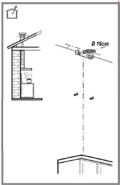
| Exhaust duct diameter | 150 mm (Ø 16 cm) |
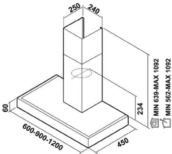
| Dimensions (width × depth × height) | 600 × 450 × 234 mm (excluding duct) |
| Approximate weight | About 12 kg |
| Power supply | 230 V, 50 Hz |
| Grease filters | Metallic, washable (in dishwasher) |
| Charcoal filters (optional) | Active, washable or non-washable (depending on model) |
| Cleaning | Surface: hot water and non-abrasive detergent. Grease filters: monthly. |
| Safety | Automatic shutdown? Not mentioned. Use by children ≥8 years under supervision. |
| Repairability | Bulb replaceable by user. Other parts: authorized after-sales service. |
| Warranty | 2 years (standard) |
Frequently Asked Questions - BOX602SS PROLINE
User questions about BOX602SS PROLINE
0 question about this device. Answer the ones you know or ask your own.
Ask a new question about this device
Download the instructions for your Range hood in PDF format for free! Find your manual BOX602SS - PROLINE and take your electronic device back in hand. On this page are published all the documents necessary for the use of your device. BOX602SS by PROLINE.
USER MANUAL BOX602SS PROLINE
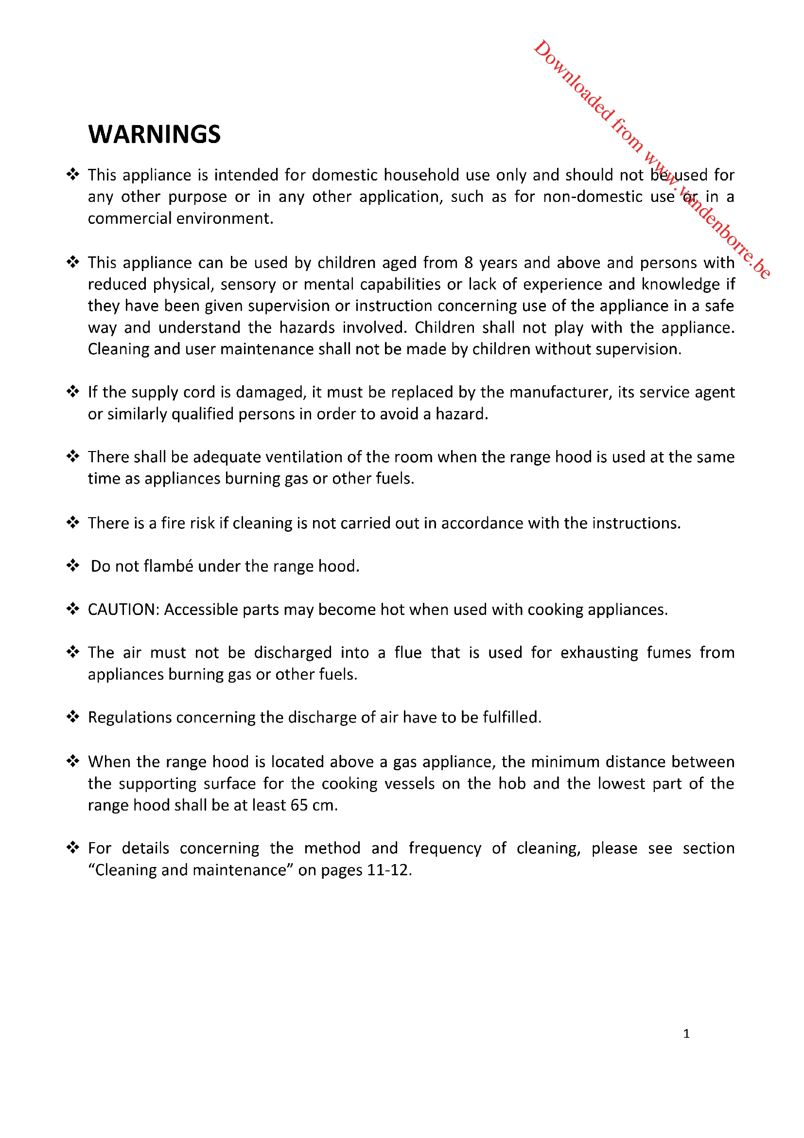
natural_image
Exterior view of a stainless steel kitchen range hood (no text or symbols visible)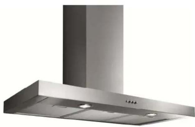
natural_image
Exterior view of a stainless steel kitchen ventilation duct (no text or symbols visible)MANUEL D'UTILISATION
OPERATING INSTRUCTIONS
HANDLEIDING
MISES EN GARDE IMPORTANTES
AVANT L'INSTALLATION
natural_image
Isometric diagram of a mechanical device with a coiled spring and housing, showing no text or symbols.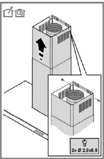

natural_image
Symbol of a trash bin crossed with no text or labelsThis appliance is intended for domestic household use only and should not be used for any other purpose or in any other application, such as for non-domestic use or in a commercial environment.
This appliance can be used by children aged from 8 years and above and persons with reduced physical, sensory or mental capabilities or lack of experience and knowledge if they have been given supervision or instruction concerning use of the appliance in a safe way and understand the hazards involved. Children shall not play with the appliance. Cleaning and user maintenance shall not be made by children without supervision.
If the supply cord is damaged, it must be replaced by the manufacturer, its service agent or similarly qualified persons in order to avoid a hazard.
There shall be adequate ventilation of the room when the range hood is used at the same time as appliances burning gas or other fuels.
There is a fire risk if cleaning is not carried out in accordance with the instructions.
Do not flambé under the range hood.
CAUTION: Accessible parts may become hot when used with cooking appliances.
The air must not be discharged into a flue that is used for exhausting fumes from appliances burning gas or other fuels.
◆ Regulations concerning the discharge of air have to be fulfilled.
When the range hood is located above a gas appliance, the minimum distance between the supporting surface for the cooking vessels on the hob and the lowest part of the range hood shall be at least 65 cm.
For details concerning the method and frequency of cleaning, please see section "Cleaning and maintenance" on pages 11-12.
IMPORTANT SAFETY INSTRUCTIONS
- Carefully read this instruction book and keep it in a safe place for future reference. In the case of sale, cession or move, make sure it is kept together with the product.
- The manufacturer declines all responsibility, for any eventual inconveniences, damages or fires caused by not complying with the instructions in this manual.
• Always wear work gloves for all installation and maintenance operations.
• Do not connect the appliance to the mains until the installation is fully complete.
• Do not carry out electrical or mechanical variations on the product or on the discharge conduit.
• Do not check the status of the filters while the range hood is operating.
• Any frying must be done with care in order to make sure that the oil does not overheat and ignite.
• Do not use the hood without the lamp correctly mounted due to the possible risk of electric shocks. - Never use the hood without effectively mounted grease filters.
• The hood must NEVER be used as a support surface. - The presence of exposed flames is detrimental to the filters and may cause a fire risk, and must therefore be avoided in all circumstances.
• Do not touch the light bulbs after operating the appliance, you might get burnt. - Before any cleaning or maintenance operation, disconnect hood from the mains by removing the plug or disconnecting the mains electrical supply.
DESCRIPTION
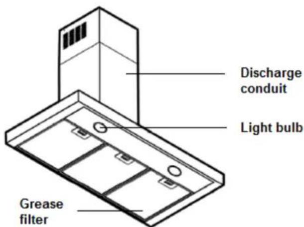
The hood is designed to be used either for ducting or filter version.

BEFORE INSTALLATION
Before proceeding with the installation of your appliance, check that it is not damaged. Otherwise, do not proceed with the installation and contact your dealer.
You should also make sure that the dimensions of the appliance and its conduit are compatible with your kitchen and ceiling height.
INSTALLATION
This appliance has to be installed by 2 people.
Expansion wall plugs are provided to secure the hood to most types of walls/ceilings. However, a qualified technician must verify suitability of the materials in accordance with the type of wall/ceiling. The wall/ceiling must be strong enough to take the weight of the hood.
WARNING! Failure to follow the instructions in this manual may result in electrical hazards.
In case of doubt, consult an authorised service assistance centre or similar qualified person.
Detailed installation procedure
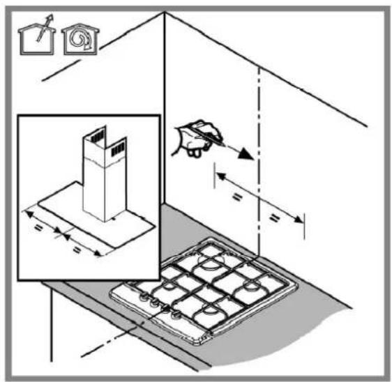
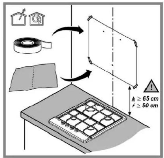
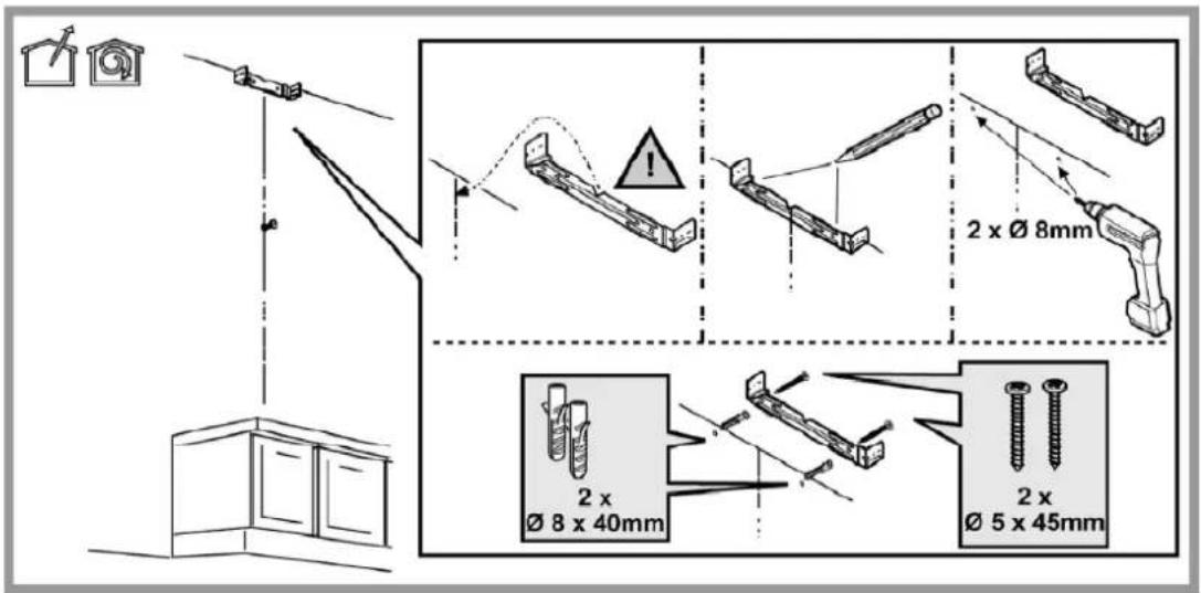
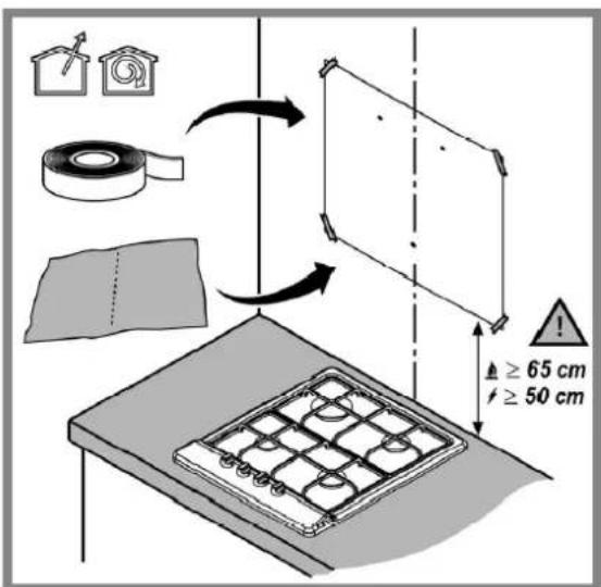
- Take the dimensions of your cooker in order to have the range hood centred above it. Stick the installation and drilling pattern on the wall above your cooker, taking care to comply with the required minimum distance.
Note: The minimum distance between the supporting surface for the cooking equipment on the hob and the lowest part of the range hood must be not less than 50cm from electric cookers and 65cm from gas or mixed cookers. If the instructions for installation for the gas hob specify a greater distance, this must be adhered to.
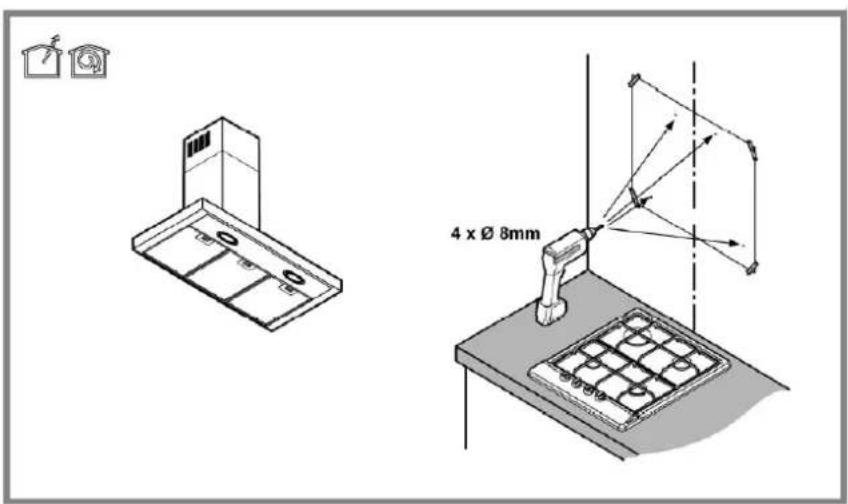
- On the wall, mark the position of the 4 holes shown on the pattern and drill the holes by using drill bit with an 8mm diameter.
Attention: the pattern is designed for 2 different range hood dimensions, therefore you must make sure to conform to the dimensions of your appliance.
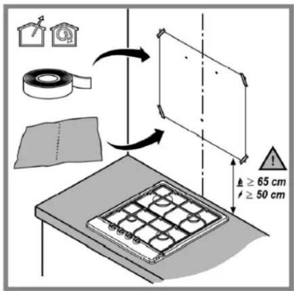
- In the holes that you just drilled, insert the 4 wall plugs (8mm diameter, 40mm depth) and the 4 screws (5mm diameter, 45mm depth), all supplied.
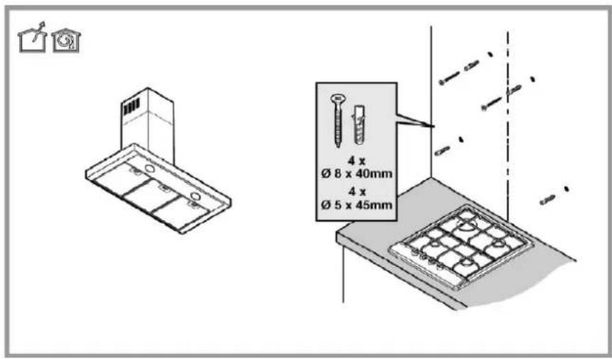
- Mark the position of 2 other holes at the top centre of the wall for installation of the discharge conduit. Screw the bracket in place.
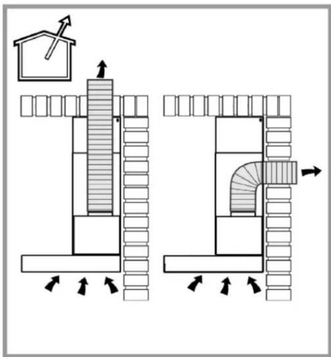
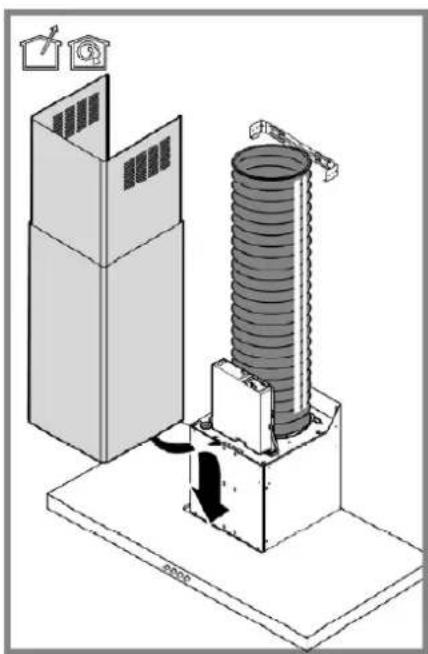
- Depending on the type of discharge in your home, mount the chimney.
Wall discharge
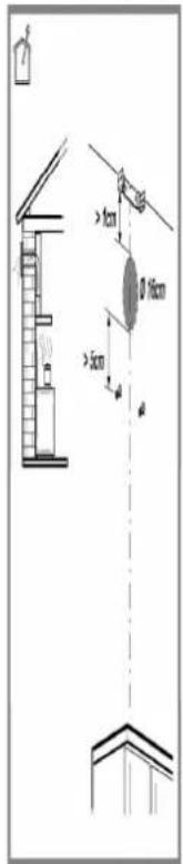
Ceiling discharge
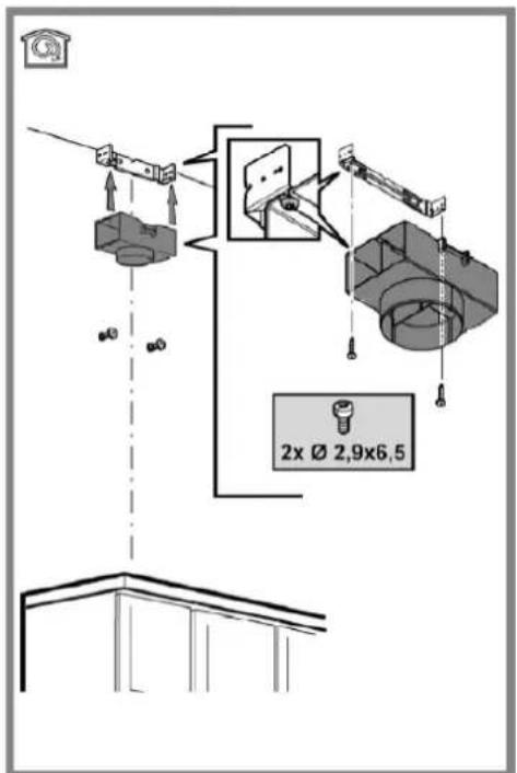
To use the appliance in filter version, fit the discharge conduit to the bracket at the top of the wall with the supplied 2 screws (2.9mm diameter, 6.5mm depth).
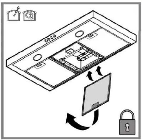
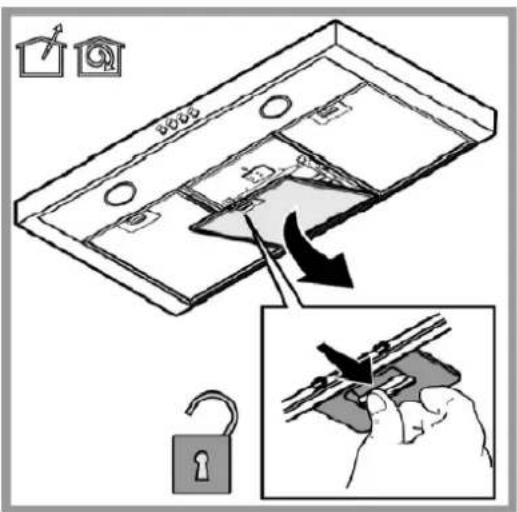
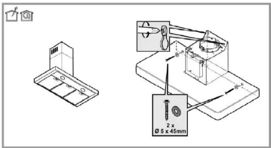
- Position the range hood on the 2 upper screws. Open the grease filter door to access the 2 screws inside the box, on each side. Remove the grease filters and position the 2 internal screws with the supplied washers.
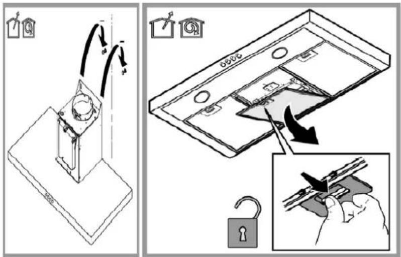
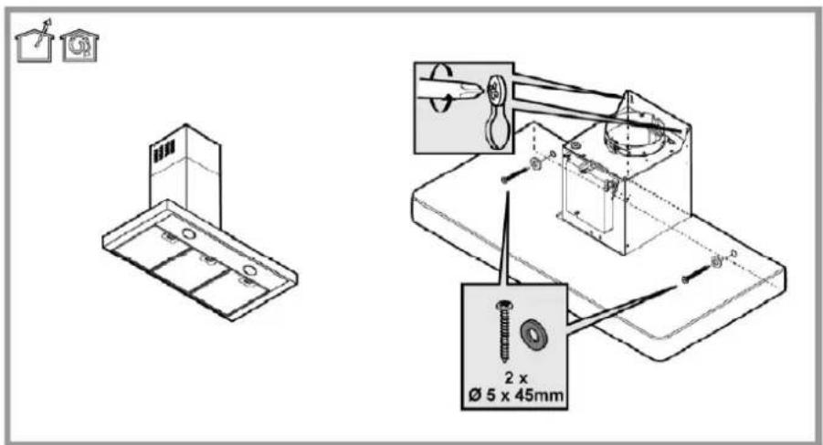
- Make sure the appliance is level by using a spirit level, and tighten the screws.
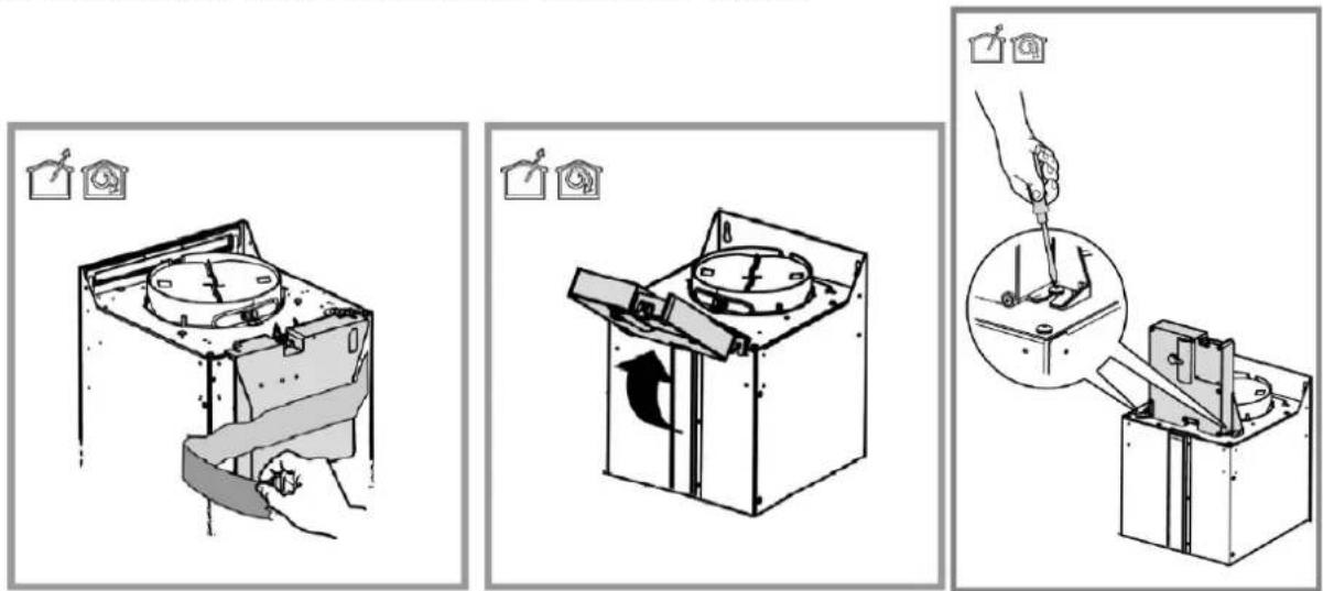
- Take off the power unit on the front of the hood and raise it up and then fasten it with the 2 screws already positioned on the top of the hood. Tighten the screws.
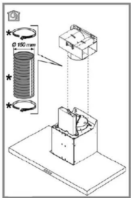
- Install an exhaust pipe (not supplied) with correct dimension.
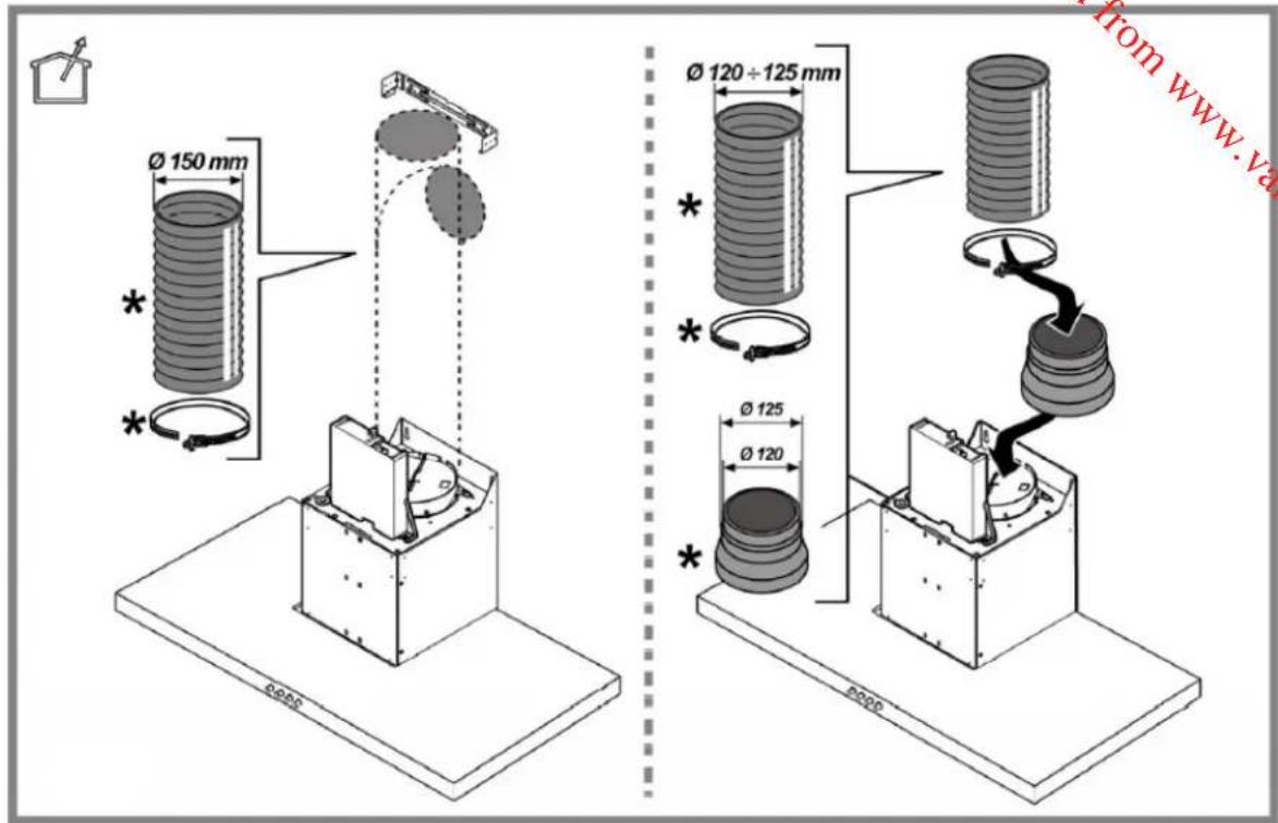
- Stretch out the pipe and fit it to the filter conduit, or connect it to the external discharge point. In case of discharging air to the outside, you can add the non-return valve before putting the pipe in place: this will help avoid backflow of air.
natural_image
Isometric diagram of a mechanical device with a coiled spring and housing, showing no text or symbols.
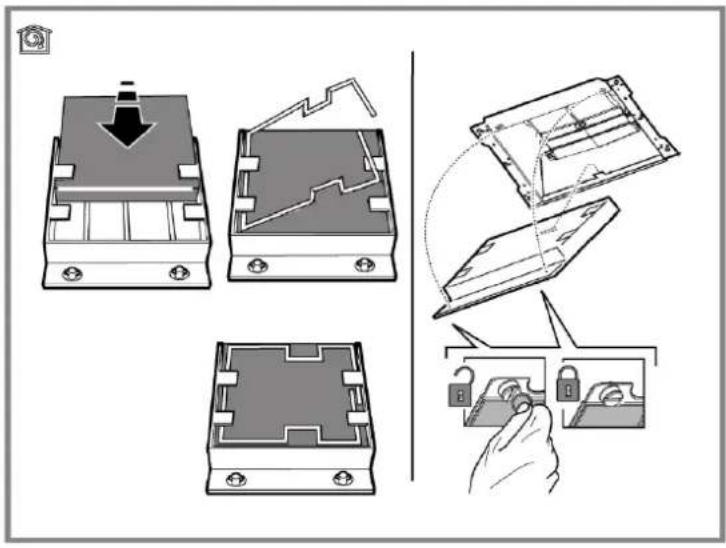
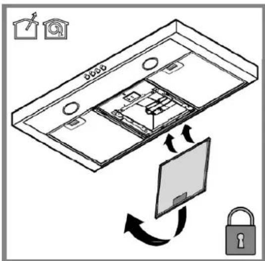
- If you wish to install charcoal filters (not supplied), to use the appliance in filter mode, follow the instructions below. After installing the charcoal filters, ensure to put the grease filters back in place.
Assembly
Hook the charcoal filter at the back on the metal tongue of the hood first, then on the front with the two knobs.
Disassembly
Remove the charcoal filter by turning the knobs fixing it to the hood by 90°.
Electrical connection
For your safety, ask a qualified technician to perform the electrical installation of the hood.
The mains power supply must correspond to the rating indicated on the plate situated inside the hood. If provided with a plug connect the hood to a socket in compliance with current regulations and positioned in an accessible area, after installation. If it not fitted with a plug (direct mains connection) or if the plug is not located in an accessible area, after installation, apply a double pole switch in accordance with standards which assures the complete disconnection of the mains under conditions relating to over-current category III, in accordance with installation instructions.
Warning! Before re-connecting the hood circuit to the mains supply and checking the efficient function, always check that the mains cable is correctly assembled.
USING YOUR APPLIANCE

Ducting version
In this case the fumes are conveyed outside of the building by means of a special pipe connected with the flange located on top of the hood.
Beware! The exhaust pipe and ring are not supplied and must be purchased apart.
Diameter of the exhausting pipe must be equal to that of the flange.
In the horizontal runs the exhausting pipe must be slightly slanted (about 10^ ) and directed upwards to vent the air easily from the room to the outside.
Beware! If the hood is supplied with active charcoal filter, then it must be removed.
Connect the hood and discharge holes on the walls with a diameter equivalent to the exhaust pipe (flange and ring). Using tubes and discharge holes on walls with smaller dimensions will affect the suction performance and drastically increase the noise.
- Use a duct of the minimum necessary length.
- Use a duct with as few elbows as possible (maximum elbow angle: 90^ ).
- Avoid drastic changes in the duct cross-section.
- Use a duct as smooth as possible inside.
- The duct must be made of certified material.
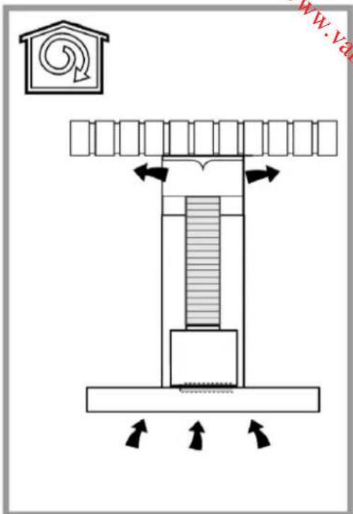
Filter version
The aspirated air will be degreased and deodorised before being fed back into the room.
In order to use the hood in this version, you have to install a system of additional filtering based on activated charcoal (for more information, please refer to Installation section of this manual).
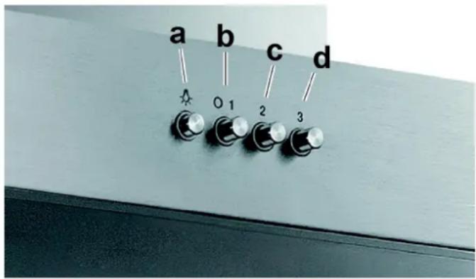
Operation
The hood is fitted with a control panel with aspiration speed selection control and a light switch to control cooking area lights. Use the high suction speed in cases of concentrated kitchen vapours.
a. ON/OFF light switch
b. Speed 1/OFF switch
c. 2-speed selection
d. 3-speed selection
Note: the switch b. is for 1-speed selection but it also acts as an on-off switch. As a result, it must be pressed if you want to select speed 2 or 3.
Tips on saving energy
Here are some suggestions to help you reduce the environmental impact of your appliance:
Switch on the hood at minimum speed when you start cooking and keep it running for a few minutes after cooking is finished. Increase the speed only in case of a large amount of smoke and vapour and use higher speed only in extreme situations. Replace the charcoal filters when necessary to maintain a good odour reduction efficiency. Clean the grease filters when necessary to maintain a good grease filter efficiency.
CLEANING AND MAINTENANCE
Beware! Before performing any cleaning or maintenance operation, isolate the hood from the electrical supply by switching off at the connector and removing the connector fuse. Or if the appliance has been connected through a plug and socket, then the plug must be removed from the socket.
The cooker hood should be cleaned regularly internally and externally (about once a month). Clean using the cloth dampened with neutral liquid detergent. Do not use abrasive products. DO NOT USE ALCOHOL!
WARNING: Failure to carry out the basic cleaning recommendations of the cooker hood and replacement of the filters may cause fire risks.
Cleaning the external surface
- To protect the external surface of the hood from corrosion over a long period of time, it should be cleaned with hot water plus non corrosive detergent every two months.
- Keep the motor and other parts free from water, as this will cause damage to the appliance.
- The charcoal filters shall not be exposed to heat.
Cleaning the grease filter
The grease filters trap cooking grease particles.
It must be cleaned once a month using non aggressive detergents, either by hand or in the dishwasher, which must be set to a low temperature and a short cycle.
When washed in a dishwasher, the grease filter may discolour slightly, but this does not affect its filtering capacity. To remove the grease filter, pull the spring release handle.
Cleaning the charcoal filters (filter version only)
The charcoal filters absorb unpleasant odours caused by cooking.
There are 2 types of activated charcoal filters: washable and non-washable activated charcoal filters.
Washable activated charcoal filter
The charcoal filter can be washed once every two months using hot water and a suitable detergent, or in a dishwasher at 65^ C (if the dishwasher is used, select the full cycle function and leave dishes out). Eliminate excess water without damaging the filter, then remove the mattress located inside the plastic frame and put it in the oven for 10 minutes at 100^ C to dry completely.
Replace the mattress every 3 years and when the cloth is damaged.
NON-washable activated charcoal filter
The saturation of the charcoal filter occurs after more or less prolonged use, depending on the type of cooking and how often you clean the grease filters. In any case, it is necessary to replace the filter at least every four months.
The charcoal filter may NOT be washed or regenerated.
Replacing lamps
Disconnect the appliance from the mains.
Warning! Prior to touching the light bulbs, ensure they are cooled down.
Replace the old light bulb with the one of the same type: use ∅35mm E14 28W halogen candle lamps only.
If the lights do not work, make sure that the lamps are fitted properly into their housings before you call for technical assistance.
SPECIFICATIONS
Below is the sheet of range hood according to EU regulation No 65/2014.
| Brand | Proline | |
| Model number BOX602SS, BOX902SS | ||
| Annual energy consumption (AEC _hood ) 122.4 kWh/year | ||
| Energy efficiency class * D | ||
| Fluid dynamic efficiency (FDE _hood ) 16.6 % | ||
| Fluid dynamic efficiency class * | D | |
| Lighting efficiency (LE _hood ) | 3.0 lux/W | |
| Lighting efficiency class * | G | |
| Grease filtering efficiency 66.0 % | ||
| Grease filtering efficiency class * | D | |
| Air flow | At minimum speed 240 m ^3 /h | |
| At maximum speed 581 m ^3 /h | ||
| Acoustic level | At minimum speed 46 dB | |
| At maximum speed 67 dB | ||
| Power consumption in off mode (P _o ) | N/A | |
| Power consumption in standby mode (P _s ) N/A | ||
* A (most efficient) to G (least efficient)
DISPOSAL
natural_image
Symbol of a trash bin crossed with diagonal lines, representing waste sorting or disposal (no text or labels)This symbol indicates that this appliance may not be treated as household waste. Instead it should be taken to the appropriate collection point for the recycling of electrical and electronic equipment. Disposal must be carried out in accordance with local environmental regulations for waste disposal.
For further detailed information regarding the process, collection and recycling of this product, please contact the appropriate department of your local authorities or the local department for household waste or the shop where you purchased this product.
WAARSCHUWINGEN
VOOR INSTALLATIE
Downloaded from www.vandenborre.be
natural_image
Diagram of a mechanical device with a handle and internal components, no visible text or symbols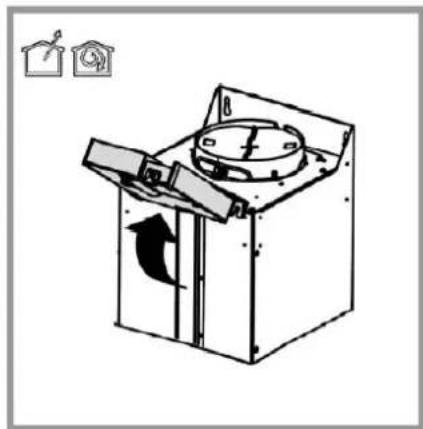
natural_image
Diagram of a mechanical device with rotating arm and housing, showing directional arrows (no text or symbols)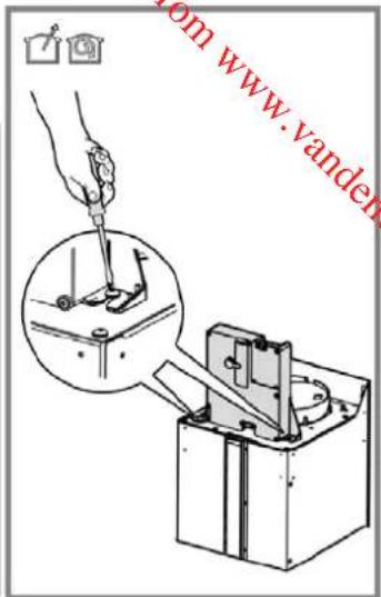
natural_image
Isometric diagram of a mechanical device with a cylindrical spring mounted on a base, showing internal components and directional arrows (no text or symbols)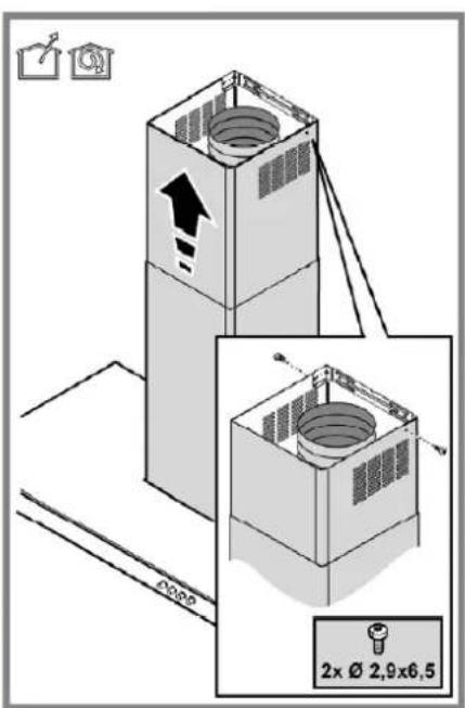
natural_image
Symbol of a trash bin crossed with no text or numbers, representing environmental protection (no text present)Downloaded from www.vandenborre.be
Downloaded from www.vandenborre.be
Downloaded from www.vandenborre.be


- MISES EN GARDE IMPORTANTES
- AVANT L'INSTALLATION
- IMPORTANT SAFETY INSTRUCTIONS
- BEFORE INSTALLATION
- INSTALLATION
- Detailed installation procedure
- Assembly
- Disassembly
- Electrical connection
- USING YOUR APPLIANCE
- Ducting version
- Filter version
- Operation
- Tips on saving energy
- CLEANING AND MAINTENANCE
- Cleaning the external surface
- Cleaning the grease filter
- Cleaning the charcoal filters (filter version only)
- Washable activated charcoal filter
- NON-washable activated charcoal filter
- Replacing lamps
- SPECIFICATIONS
- DISPOSAL
- WAARSCHUWINGEN
- VOOR INSTALLATIE
Brand : PROLINE
Model : BOX602SS
Category : Range hood