F 137 - Heating Jøtul - Free user manual and instructions
Find the device manual for free F 137 Jøtul in PDF.
| Product type | Wood stove |
| Brand | Jøtul |
| Model | F 137 |
| Material | Cast iron / Steel |
| Finish | Black paint |
| Connection | Top, rear |
| Connection diameter | ∅150 mm |
| Fresh air intake diameter | ∅100 mm |
| Nominal power output | 4.7 kW |
| Efficiency | 83 % |
| Fuel | Wood only |
| Maximum log length | 20 cm |
| Nominal hourly consumption | 1.52 kg/h |
| Max ignition wood quantity | 1.54 kg |
| Operating draft | 16 Pa |
| Flue gas temperature (EN 13240) | 260 °C |
| Operation | Intermittent |
| Safety distances (combustible materials) | See diagram (fig.1): min. 900 mm radius, variable wall distances |
| Maintenance | Glass cleaning, annual chimney sweeping, gasket replacement |
| Warranty | 25 years cast iron parts (if registered), 5 years steel |
| Options | Fresh air intake kit ∅100 mm |
Frequently Asked Questions - F 137 Jøtul
User questions about F 137 Jøtul
0 question about this device. Answer the ones you know or ask your own.
Ask a new question about this device
Download the instructions for your Heating in PDF format for free! Find your manual F 137 - Jøtul and take your electronic device back in hand. On this page are published all the documents necessary for the use of your device. F 137 by Jøtul.
USER MANUAL F 137 Jøtul
UK - Installation and Operating Instructions 5
natural_image
Four identical gray industrial fire extinguishers with visible flames inside, arranged side by side (no text or symbols)UK - Register your fi replace at jotul.com for a 25-year warranty.
Installation manual with technical data
1.0 Relationship to the authorities ....5
2.0 Technical data 5
3.0 Safety 6
4.0 Installation 12
5.0 Daily use 21
6.0 Maintenance 22
7.0 Service.... 22
9.0 Optional Equipment 24
10. Troubleshooting 24
10.0 Recycling 25
11 Guarantee terms 25
UK - Register your fireplace at jotul. com for a 25-year warranty.
text_image
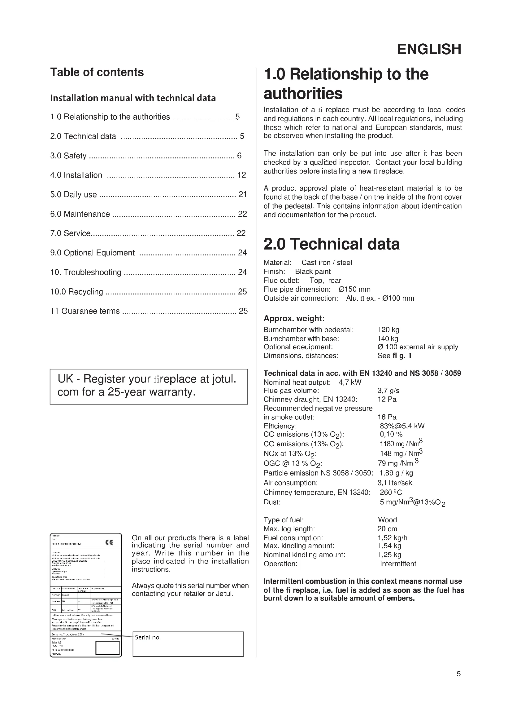
Formular Detail • Section 14 (see Section 14) Standard Chinese in accordance with an official standard formular. Chinese in accordance with an official standard formular. The applicable standards are not specified. Special requirements: Special requirements: Special requirements: Special requirements: General requirements: General requirements: Country Classification Documentaries Application Approvals Name: Standard Balance: 2000 GF SP Disrupts from the above Standard requirements: Sub-Section Formular Safes zur Inserderivate. Ubrige verrechnenden lads Montage und Bedienungsanleitung beizahlen. Weronder bilum ergröten einen Brandenheiten. Rechteftes zusätzlichen Definition. Utilized unlegungen. we consumitieren recommends. Serial No. 2000, Year 2000 Manufacturer: 22.145 Date: April 2003-14-01 M-18/02 Freibelskapet MontageOn all our products there is a label indicating the serial number and year. Write this number in the place indicated in the installation instructions.
Always quote this serial number when contacting your retailer or Jøtul.
Serial no.
1.0 Relationship to the authorities
Installation of a fi replace must be according to local codes and regulations in each country. All local regulations, including those which refer to national and European standards, must be observed when installing the product.
The installation can only be put into use after it has been checked by a qualified inspector. Contact your local building authorities before installing a new file replace.
A product approval plate of heat-resistant material is to be found at the back of the base / on the inside of the front cover of the pedestal. This contains information about identification and documentation for the product.
2.0 Technical data
Material: Cast iron / steel
Finish: Black paint
Flue outlet: Top, rear
Flue pipe dimension: ∅150 mm
Outside air connection: Alu. fl ex. - ∅100 mm
Approx. weight:
Burnchamber with pedestal: 120 kg
Burnchamber with base: 140 kg
Optional equipment: ∅ 100 external air supply
Dimensions, distances: See fi g. 1
Technical data in acc. with EN 13240 and NS 3058 / 3059
Nominal heat output: 4,7 kW
Flue gas volume: 3,7 g/s
Chimney draught, EN 13240: 12 Pa
Recommended negative pressure
in smoke outlet: 16 Pa
Efficiency: 83%@5,4 kW
CO emissions (13% O₂): 0,10 %
CO emissions (13% O _2 ): 1180 mg / Nm ^3
NOx at 13% O₂: 148 mg / Nm³
OGC @ 13 % O₂: 79 mg /Nm³
Particle emission NS 3058 / 3059: 1,89 g / kg
Air consumption: 3,1 liter/sek.
Chimney temperature, EN 13240: 260 °C
Dust: 5 mg/Nm ^3 @13%O _2
Type of fuel: Wood
Max. log length: 20 cm
Fuel consumption: 1,52 kg/h
Max. kindling amount: 1,54 kg
Nominal kindling amount: 1,25 kg
Operation: Intermittent
Intermittent combustion in this context means normal use of the fi replace, i.e. fuel is added as soon as the fuel has burnt down to a suitable amount of embers.
ENGLISH
3.0 Safety
NB! To guarantee optimal performance and safety, Jøtul recommends that its stoves are fitted by a qualified installer (see www.jotul.com for a complete list of dealers).
Any modifications to the product may result in the product and safety features not functioning as intended. The same applies to the installation of accessories or optional extras not supplied by Jøtul. This may also be the case if parts that are essential to the functioning and safety of the fi replace have been disassembled or removed.
In all these cases, the manufacturer is not responsible or liable for the product and the right to make a complaint becomes null and void.
Note! Parts of the stove, especially the external surfaces become hot during use. Caution!
The Clean Air Act
"The Clean Air Act 1993 and Smoke Control Areas"
Under the Clean Air Act local authorities may declare the whole or part of the district of the authority to be a smoke control area. It is an offence to emit smoke from a chimney of a building, from a furnace or from any fixed boiler if located in a designated smoke control area. It is also an offence to acquire an “unauthorised fuel” for use within a smoke control area unless it is used in an “exempt” appliance (“exempted” from the controls which generally apply in the smoke control area). The Secretary of State for Environment, Food and Rural Affairs has powers under the Act to authorise smokeless fuels or exempt appliances for use in smoke control areas in England. In Scotland and Wales this power rests with Ministers in the devolved administrations for those countries. Separate legislation, the Clean Air (Northern Ireland) Order 1981, applies in Northern Ireland. Therefore it is a requirement that fuels burnt or obtained for use in smoke control areas have been “authorised” in Regulations and that appliances used to burn solid fuel in those areas (other than “authorised” fuels) have been exempted by an Order made and signed by the Secretary of State or Minister in the devolved administrations. Further information on the requirements of the Clean Air Act can be found here: http://smokecontrol.defra.gov.uk/
Your local authority is responsible for implementing the Clean Air Act 1993 including designation and supervision of smoke control areas and you can contact them for details of Clean Air Act requirements".
Your local authority is responsible for implementing the Clean Air Act 1993 including designation and supervision of smoke control areas and you can contact them for details of Clean Air Act requirements"
3.1 Fire Prevention Measures
There is a certain element of danger every time you use your fi replace. The following instructions must therefore be followed:
- The minimum safety distances when installing and using the fireplace are given in fig. 1. The specified distance to fl ammable materials, applies to this stove. The stove must be installed with a CE approved flue. The distance of the fl ue pipe to combustible materials must also be observed.
- Ensure that furniture and other flammable materials are not too close to the fireplace. Flammable materials should not be placed within 900 mm of the fi replace.
- Allow the fire to burn out. Never extinguish the flames with water.
- The fireplace becomes hot when lit and may cause burns if touched.
- Only remove ash when the fireplace is cold. Ash can contain hot embers and should therefore be placed in a non-fil ammable container.
- Ash should be placed outdoors or be emptied in a place where it will not present a potential fire hazard.
In case of chimney fire:
- Close all hatches and vents.
- Keep the firebox door closed.
- Check the loft and cellar for smoke.
- Call the fire service.
- Before use after a fire an expert must check the fireplace and the chimney in order to ensure that it is fully functional.
3.2 Floor
Foundation
You need to make sure the foundation is suitable for a fireplace. See “2.0 Technical Data” for specified weight.
We recommend the removal of any flooring that is not attached to the foundation (“floating floors”) beneath the installation.
Requirements for protection of inflammable floors in front of the fireplace
The front plate must comply with national laws and regulations.
Contact your local building authorities regarding restrictions and installation requirements.
The purpose of a floor plate is to protect the floor and combustible material from embers.
Note! The space underneath the burnchamber of Jøtul F 134 / Jøtul F 135 (product with base) cannot be used for wood storage or for any other combustible material.
3.4 Walls
Distance to walls made of combustible material - see fig. 1a and 1c.
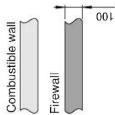
Distance to combustible wall protected by firewall: - see fig. 1b and 1d.
The fireplace may be used with an uninsulated flue pipe provided the distances between the fi replace and walls made of combustible materials are as shown in fi g. 1a and 1c. Distances to combustibile material using semi insulated or shielded flue pipe are also shown in fig. 1a and 1c.
Ensure that furniture and other fl ammable materials are not too close to the fi replace. Flammable materials should not be placed within 900 mm of the fireplace.
Make sure that furniture and other household items are not so close as to get dried up by the stove.
Fresh air supply
The air used for combustion in any well-insulated house needs to be replaced. This is particularly important in houses with mechanical ventilation. Such replacement air can be procured in several ways. The most important thing is to supply the air to the room where the stove is placed. Place the outside wall valve as close to the stove as possible and make sure that it can be closed when the stove is not in use.
For the fresh air supply connection, follow the national and local building regulations.
Important! Ensure that air vents in the room where the fi replace is located are not blocked.
Closed combustion system
Use the stove's closed combustion system if you live in recently built, airtight dwellings. Connect the external combustion air through a ventilation pipe through the wall or the floor.
Air supply
The amount of combustion air for Jøtul's products is approximately 20-40 m ^3 /h. The outside air connection may be fitted directly to the Jøtul F 130 through:
- the bottom
- through a flexible supply hose from the outside/chimney (only if the chimney has its own duct for external air) and to the product's outside air connector.
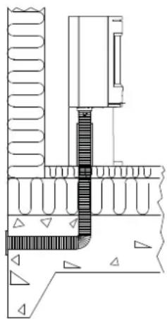
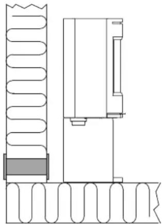
Figur 2A, Through an outside wall
natural_image
Technical line drawing of a mechanical assembly with layered components and grooves (no text or symbols)Figur 2B, Through the floor and ground plate
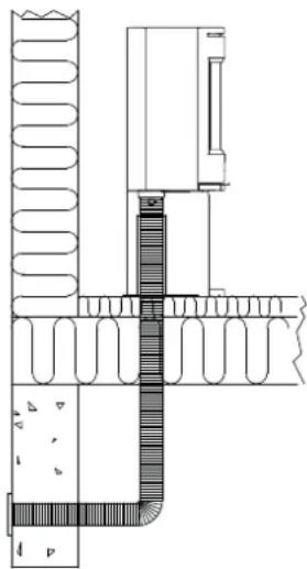
natural_image
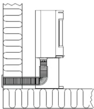
Architectural cross-section diagram showing wall and floor construction with no visible text or symbolsFigur 2C, Through the floor and basement
natural_image
Technical cross-section diagram of a mechanical or architectural component with layered structure (no text or symbols)Figur 2D, Indirectly through an outside wall
natural_image
Technical line drawing of a mechanical assembly with spring-loaded components and a vertical component (no text or symbols)Jøtul F 134 (with base / without sideglasses)
Jøtul F 136 (with pedestal without sideglasses)

Min. distance to combustible wall
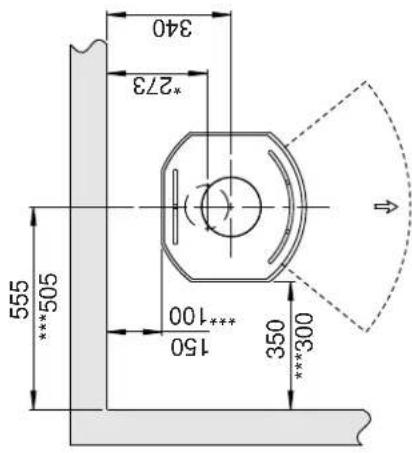
text_image
555 ***505 150 ***100 350 ***300 *273 340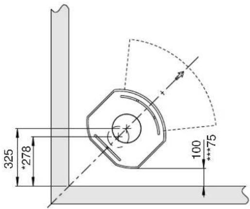
text_image
325 *278 100 ***75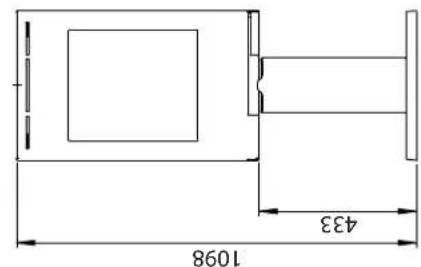
text_image
1098 433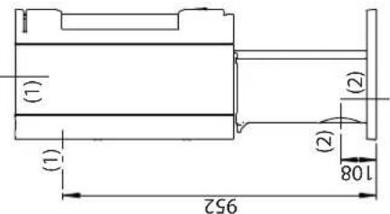
text_image
(1) (1) 952 (2) 108 (2)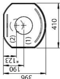
text_image
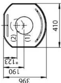
396 190 *123 (2) (1) 410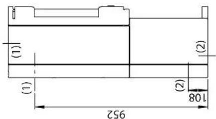
text_image
(1) (1) 952 (2) 108 (2)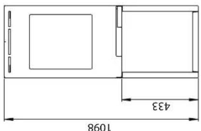
text_image
1098 433(1) - Flue pipe center
(2) - Outside air connection center
text_image
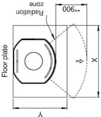
396 190 *123 (2) (1) 410Min. measurements floorplate
X / Y = According to national laws and regulations
text_image
Floor plate Y Radiation zone **900 X* Outside air connection
** Min. distance to furniture / combustible material
*** Distance to combustible wall with semi-insulated / shielded flue pipe
Jotul F 134 / F 136 - min. distance to firewall
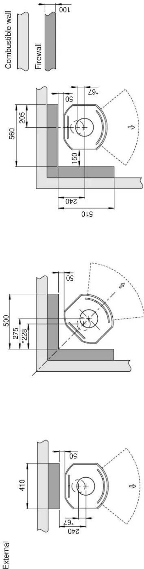
text_image
120 150 *67 50 230 686 566 240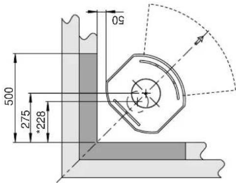
text_image
50 275 500 *228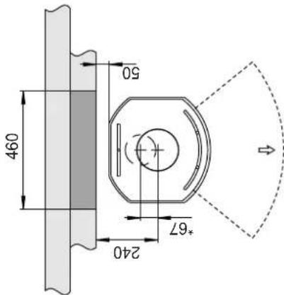
text_image
460 50 240 *67Integrated
Jøtul F 130 Series
Fig. 1c
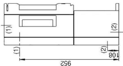
Jøtul F 135 (with base and sideglasses)
text_image
(1) (1) 952 (2) 108 (2)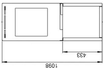
text_image
1098 433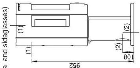
text_image
al and sideglasses) (1) (1) 952 (2) 108 (2)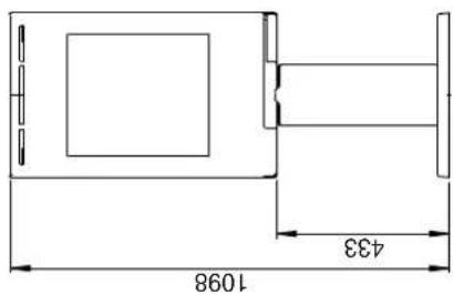
text_image
1098 433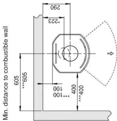
text_image
Min. distance to combustible wall 605 ***605 100 *223 290 400 ***400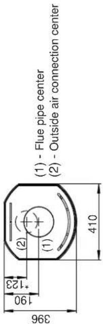
text_image
(1) - Flue pipe center (2) - Outside air connection center 396 190 *123 (2) (1) 410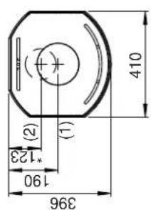
text_image
396 190 *123 (2) (1) 410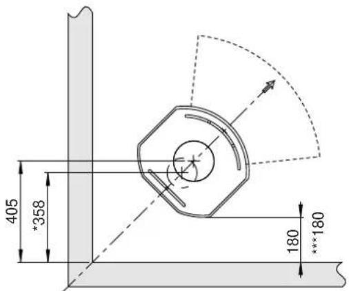
text_image
405 *358 180 ***180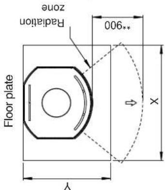
text_image
Floor plate Y Radiation zone **900 XMin. measurements floor plate
X / Y = According to national laws and regulations
* Outside air connection
** Min. distance to furniture / combustible material
*** Distance to combustible wall with semi-insulated / shielded flue pipe
Fig. 1d
Jøtul F 130 Series
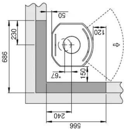
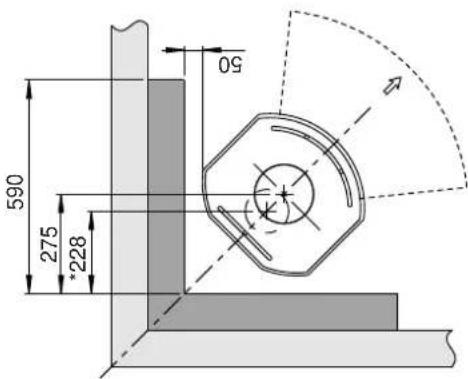
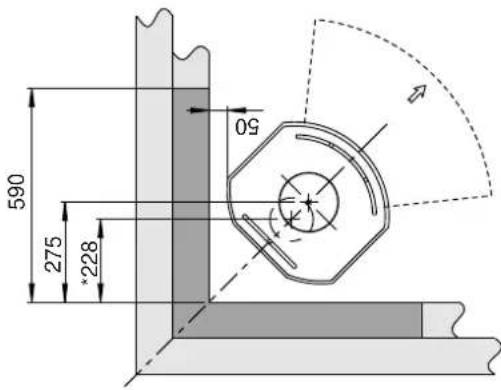
Jøtul F 135 / F 137 - min. distance to firewall
External
text_image
590 275 *228 50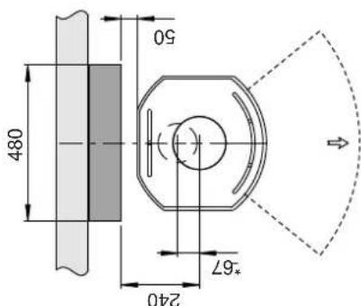
text_image
480 240 *67 50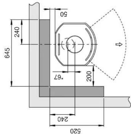
text_image
645 240 520 240 *67 200 50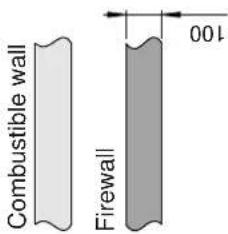
text_image
Combustible wall Firewall 100Integrated
text_image
590 275 *228 50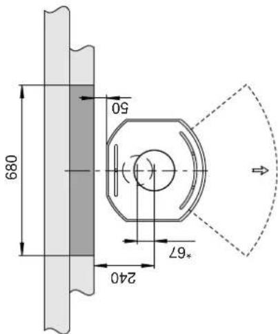
text_image
680 240 50 *67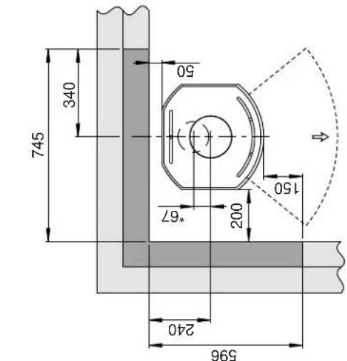
text_image
745 340 240 *67 50 200 150 596* External air supply
text_image
Combustible wall Firewall 100900196-P01
ENGLISH
4.0 Installation
- Before installing the fi replace, check it carefully for any signs of damage.
- The product is heavy! Ask someone to help you when positioning and installing it.
- Make sure that furniture and other household items are at a safe distance from the fi replace to protect them from drying out.
- Do not place anything on the top plate of the stove as this could cause permanent damage to the paint/enamel.
4.1 Prior to installation
- When the product is unpacked, take out the ash pan and its contents, the fire grate, burn plates, bafie plates, exhaust defi ector and the cover plate for the external air supply before the stove is being used for the fi rst time.
4.1 Preparations - Jøtul F 134 / F 135 with base
Fig. 3
natural_image
Technical illustration of a mechanical device with labeled components (A, B) and no visible text or symbols beyond labels- Remove the four transport screws (A) that fasten the stove to the wooden pallet.
- Leave the stove standing on the transport pallet.
- Remove the gloves from the ash pan.
- Remove the baff e, inner bottom plate, and bag of screws from the burn chamber.
- Check that the control levers (B) move easily.
Fig. 4
text_image
Technical diagram of a mechanical device with labeled components A and B, showing internal structure and assembly.- Fit the height adjustment screws (A) together with plastic caps (B) which are in the bag of screws. NB: If using the glass floor plate option, the stove must be raised approx. 8 mm off the floor to allow the floor plate to be slid under the front edge of the base.
- Lift the stove off the pallet.
- Perform a trial installation of the stove, using the 4 height adjustment screws to ensure it is horizontal.
- Mark on the wall if there are to be rear vents for the flue pipe and/or outside air supply. NB: Make allowance for the height of the fl oor plate.
Outside air connection through rear outlet
Fig. 5
natural_image
3D technical drawing of a mechanical part with a hammer and labeled component (no text or symbols beyond labels)- If the external air supply is to be provided by attaching a flex hose ( 100 mm) to the outside air connector underneath the burn chamber, knock out the removable cover plate (A) first.
Fig. 7
natural_image
Technical line drawing of a mechanical device with labeled component A (no text or symbols beyond label)- Fit the supplied plate (A) to hide the outside air hose.
Fig. 6

text_image
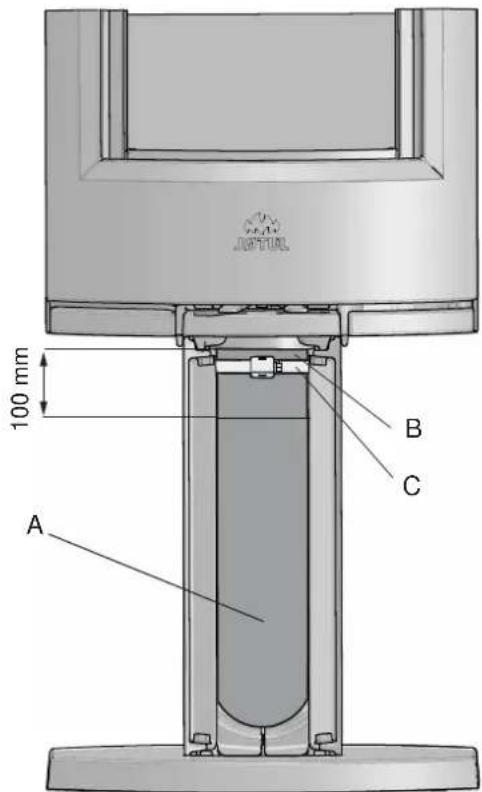
B C 100 mm A- For attaching the ∅ 100 mm outside air hose (A) (optional fitting - item no. 51012164), refer to the manual (10026187) supplied with the outside air set. Attach the hose to the outside air connector (B) using a hose clip (C). Terminate the insulation approx. 100 mm below the burn chamber.
Outside air connection through the base
Fig. 8
natural_image
3D rendering of a portable kitchen appliance with a handle and circular base, labeled A (no text or symbols on the device itself)- Knock out the bottom cover (A) with a hammer.
- Place the stove in its intended position. See fig. 1 for correct placement with regard to safe distances.
ENGLISH
Fig. 9
text_image
100 mm A B C- For attaching the ∅ 100 mm outside air hose (A) (optional fitting - item no. 51012164), refer to the manual (10026187) supplied with the outside air set. Attach the hose to the outside air connector (B) using a hose clip (C). Terminate the insulation approx. 100 mm below the burn chamber.
Fig. 10
natural_image
Technical diagram of a mechanical component with labeled section A, showing internal structure and mounting features (no readable text or symbols)- Fit the supplied plate (A) to hide the outside air hose.
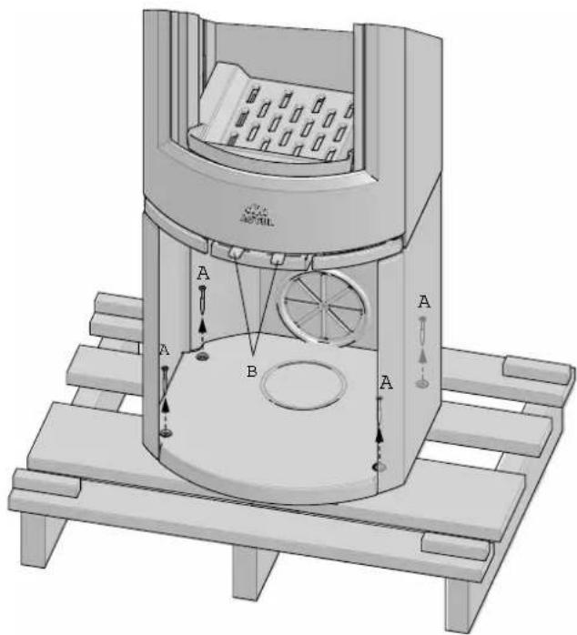
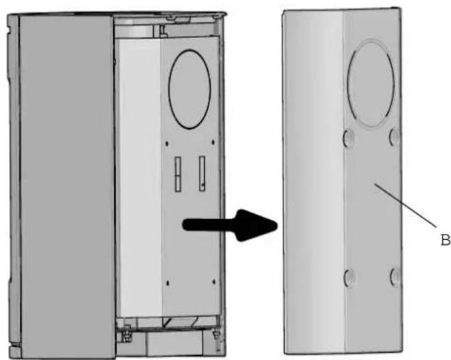
4.2 Preparations for Jøtul F 136 / F 137 with pedestal
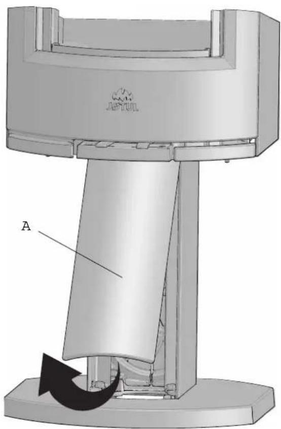
Fig. 11
text_image
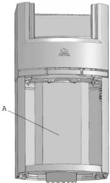
A B- Lift the front cover (A) on the pedestal up and forwards and put it to one side.
- Unscrew the transport screw (B) and remove it.
- Replace the front cover (A).
- Lift the stove off the pallet
Fig. 12
natural_image
Technical diagram of a mechanical assembly with labeled components and directional arrows (no readable text or symbols)- Screw in the supplied height adjustment screws (A) with plastic caps (B) which are in the bag of screws. NB: If using the glass floor plate option, the stove must be raised approx. 8 mm off the floor to allow the floor plate to be slid under the front edge of the pedestal.
Outside air connection through rear outlet in pedestal
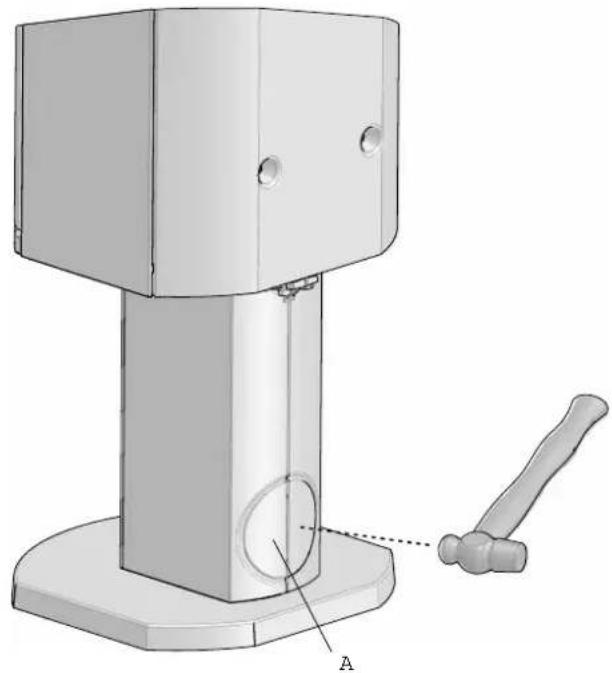
Fig. 13
natural_image
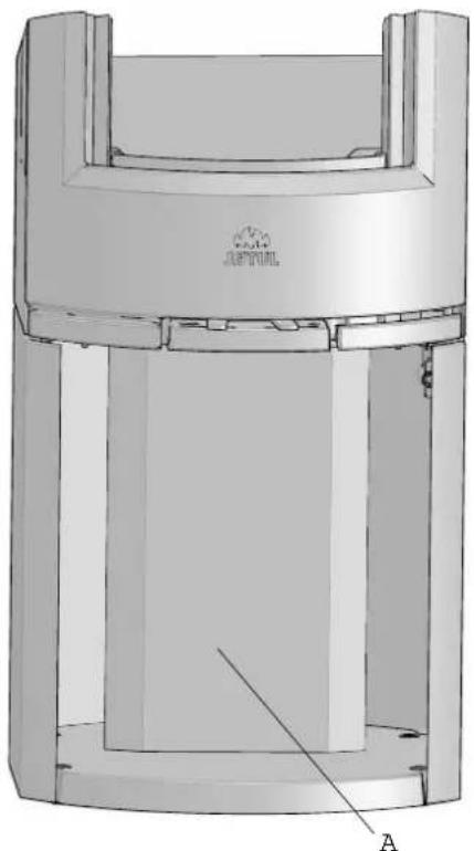
3D mechanical assembly diagram showing a base with a gavel and labeled component A (no text or symbols beyond labels)-
Knock out the rear cover (A) in the pedestal with a hammer.
-
Place the stove in its intended position. See fig. 1 for correct placement with regard to safe distances.
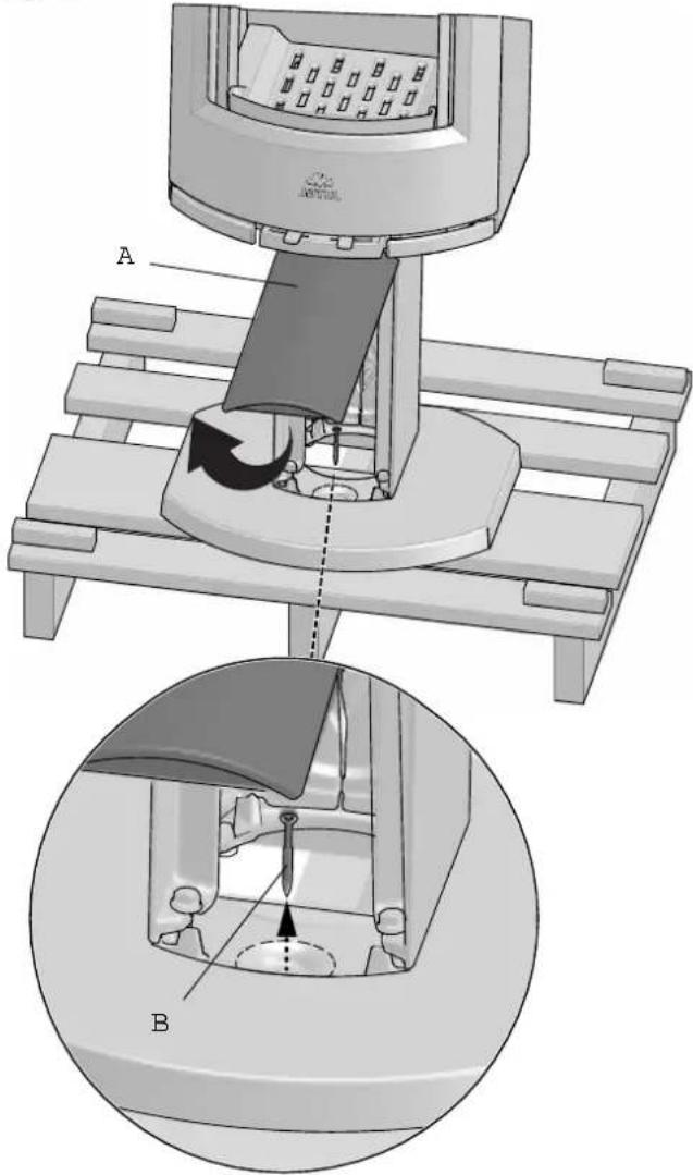
Fig. 14
natural_image
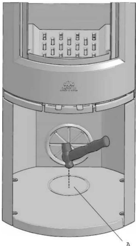
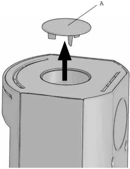
3D mechanical assembly diagram showing a lever mechanism with labeled component A and rotational arrow (no text or symbols beyond labels)- Remove the cover (A) on the front of the pedestal by lifting it up and forwards. Place it to one side..
ENGLISH
Fig. 15
text_image
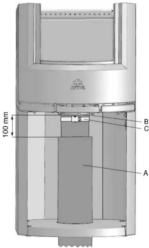
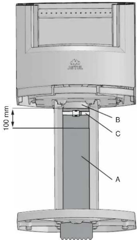
A 100 mm B C- For attaching the ∅ 100 mm outside air hose (A) (optional fl tting - item no. 51012164), refer to the manual (10026187) supplied with the outside air set. Attach the hose to the outside air connector (B) using a hose clip (C). Terminate the insulation approx. 100 mm below the burn chamber.
- Replace the front cover on the pedestal.
Outside air connection through the base of the pedestal
Fig. 16
text_image
A B C 100 mm- Remove the cover (A) on the front of the pedestal by lifting it up and forwards. Place it to one side (see fig. 14).
- For attaching the ∅ 100 mm outside air hose (A) (optional fl tting - art. no. 51012164), refer to the manual (10026187) supplied with the outside air set. Attach the hose to the outside air connector (B) using a hose clip (C). Terminate the insulation approx. 100 mm below the burn chamber.
- Replace the front cover on the pedestal.
4.3 Chimney and fl ue pipe
- The fi replace must only be connected to a chimney and flue pipe approved for solid fuel fireplaces with flue gas temperatures as specified in «2.0 Technical Data».
- The specified distance to flammable materials, applies to this stove.
- The stove must be installed with a CE approved fl ue.
- The distance of the flue pipe to combustible materials must also be observed.
- The cross-section of the chimney must be designed to fit the fireplace. Use «2.0 Technical Data» to calculate the correct chimney cross-section.
- The chimney must be connected in accordance with the installation instructions of the chimney supplier.
- Before a hole is made in the chimney, the product should be test-mounted in order to correctly mark the position of the fireplace and the hole in the chimney. See fig. 1 for minimum dimensions.
-
With a rear outlet, use a flue pipe bend with a sweep hatch to allow sweeping.
-
Please note that it is extremely important for connections to have a degree of exibility. This is to prevent any movement in the installation leading to the formation of cracks.
- For recommended chimney draught, see «2.0 Technical Data». For flue pipe dimension see “2.0 Technical Data”. NB: The chimney's diameter must be at least just as big as the fl ue pipe.
NB! The minimum recommended chimney length is 3.5 m from the flue pipe insert. If the draught is too strong, a flue pipe damper can be installed and used to reduce the draught
How wind and weather affect the stove
The performance of the stove can be affected considerably by the wind acting on the chimney at different strengths. It may therefore be necessary to adjust the air supply to ensure good combustion performance. It might also be a good idea to install a damper in the fl ue pipe so that the chimney draught can be regulated according to the strength of the wind.
Fog and mist can have a significant impact on the chimney draught and it might be necessary to use other combustion air settings to ensure good performance
The importance of the chimney
The chimney is the engine that drives the fi replace and it's essential to have a good chimney in order for the fi replace to function properly.
The draught in the chimney creates a vacuum in the stove. The combustion air is also used for the airwash system that keeps the window clear of soot.
The draught in the chimney is caused by the difference in temperatures inside and outside the chimney. The greater the temperature difference, the better the draught in the chimney. It is therefore important to allow the chimney to reach operating temperature before adjusting the air vents to restrict combustion in the stove (a brickwork chimney takes longer to reach operating temperature than a steel chimney).
It is particularly important to reach operating temperature as quickly as possible on days on which the draught in the chimney is poor due to unfavourable wind and weather conditions. Make sure the fuel ignites as quickly as possible. Practical tip: Chop the wood into much smaller pieces and use an extra fire lighter.
NB: If the stove has not been used for some considerable time, it is important to check the chimney pipe for blockage.
4.4 Fitting a fl ue pipe with a top outlet The product is supplied from the factory with the smoke outlet fitted for the top outlet.
Fig. 17
natural_image
3D technical illustration of a mechanical component with a labeled part (A) and an arrow indicating direction, no text or symbols present.- Remove the smoke-outlet cover (A).
Fig. 18
text_image
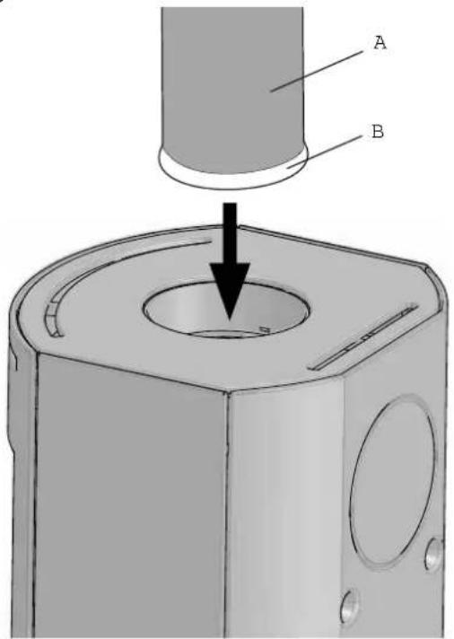
Technical diagram showing a mechanical component with labeled parts A and B, and an arrow indicating a process or assembly.- Place the gasket (B) on the edge of the flue pipe (A).
- Feed the flue pipe through the top plate and position it in the top smoke outlet.
ENGLISH
4.5 Fitting a fl ue pipe with a rear outlet
The product is supplied from the factory with the smoke outlet fitted for the top outlet. To use the rear outlet, proceed as follows
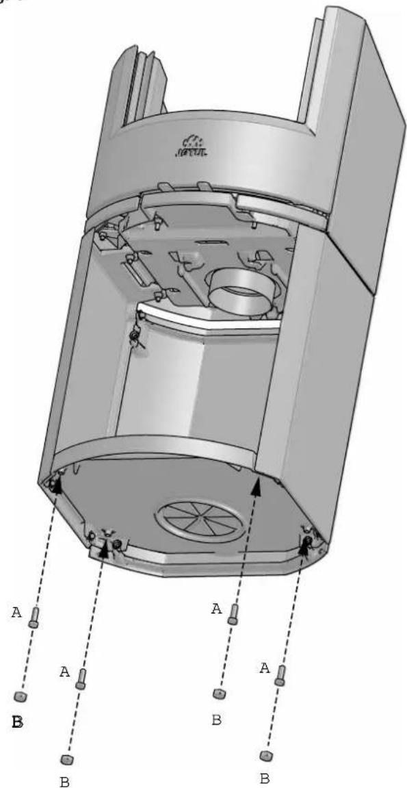
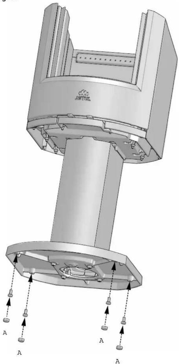
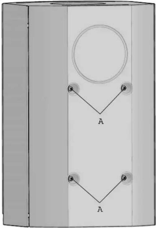
Fig. 19
natural_image
Diagram of a rectangular box with a circular top and two downward-pointing triangles labeled 'A' (no text or symbols beyond labels)- Remove the four screws (A).
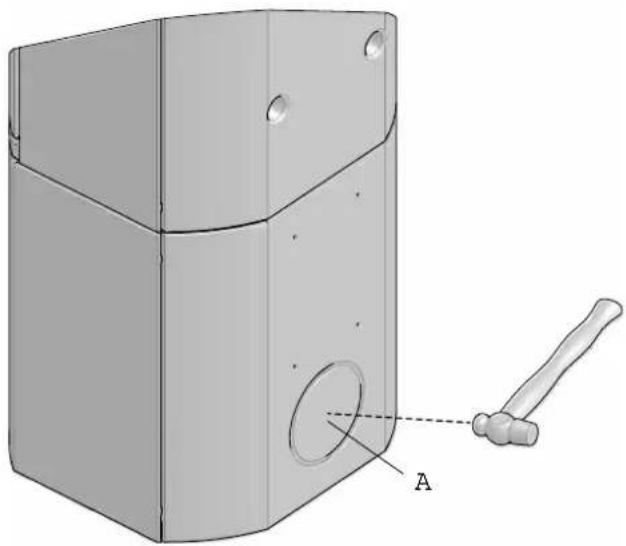
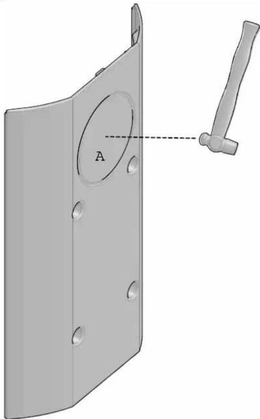
Fig. 21
natural_image
3D mechanical part diagram showing a bracket with holes and a hand tool, labeled 'A' (no text or symbols beyond label)- Knock out the cover (A) with a hammer.
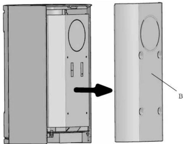
Fig. 20
natural_image
Technical diagram showing a 3D model of a cabinet with internal compartments and a separate view labeled B (no text or symbols present)- Unhook the rear plate (B).
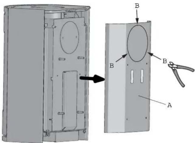
Fig. 22
text_image
Technical diagram of a device casing with labeled components A and B, showing internal compartments and part assembly.- Lift off the inner rear plate (A).
- Then clip out the cover at the four points shown (B).
Fig. 23
text_image
B A A A- Cut the supplied gasket (A) into three lengths to fit the tabs. Place the gaskets on the ends on the three
- tabs on the top cover (B).
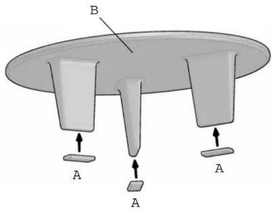
Fig. 24
text_image
Technical diagram of a mechanical device with labeled components A, B, C, D and directional arrows indicating assembly or movement.- Lift off the top cover (A) and the top plate (B) and place them to one side.
- Unscrew the screws in the rear smoke outlet cover (C) and remove the cover.
- Unscrew the smoke outlet (D).
Fig. 25
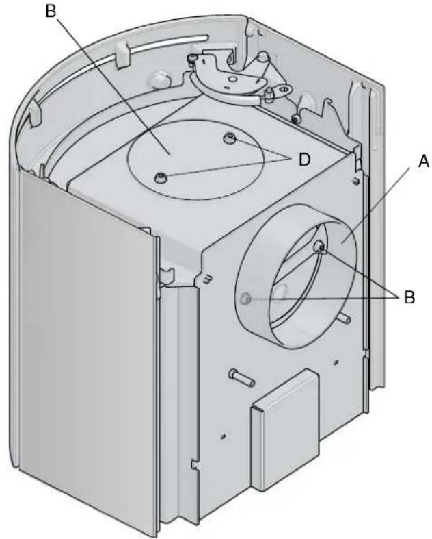
text_image
Technical diagram of a mechanical device with labeled components A, B, and D- Fit the smoke outlet (A) to the rear vent and screw it on with the same screws (B) that it was attached with.
- Fit the smoke outlet cover (C) to the top outlet using the same screws (D) that it was attached with
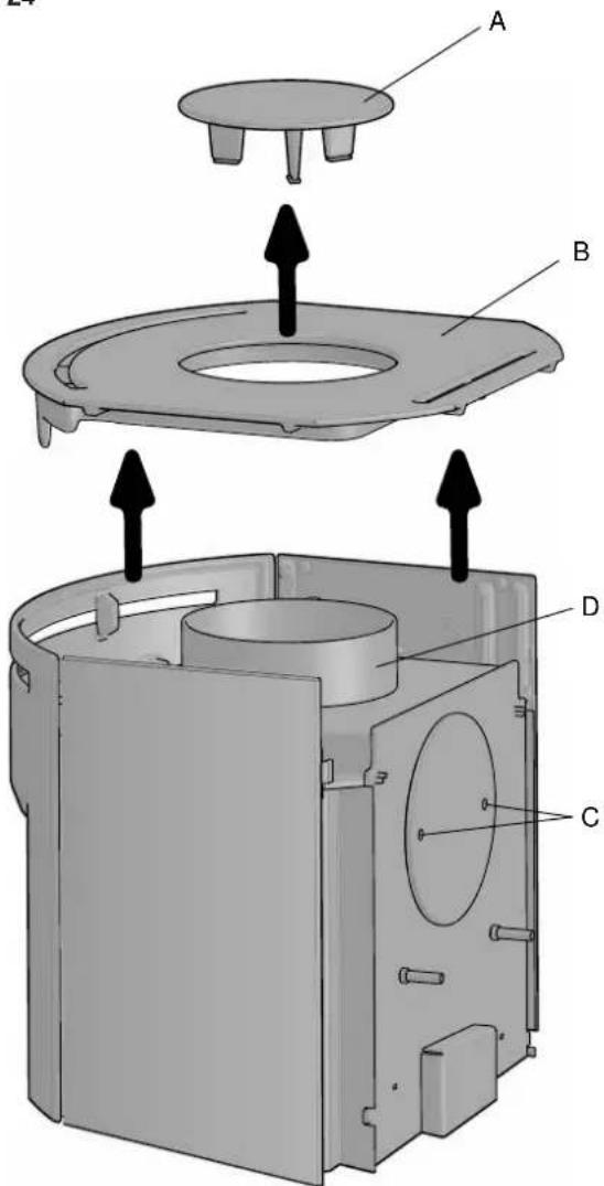
Fig. 26
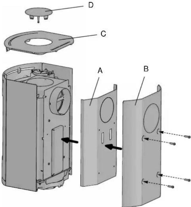
text_image
Exploded view diagram of a device showing internal components labeled A, B, C, D with arrows indicating assembly or assembly steps.- Position the inner (A) and outer (B) rear plates on the burn chamber and screw them on using the same 4 screws they were attached with.
- Fit the top plate (C) and top cover (D).
ENGLISH
Fig. 27
natural_image
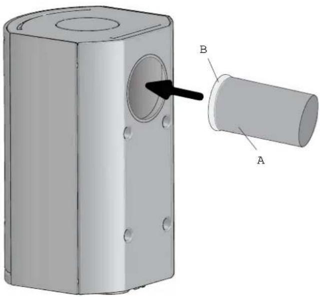
3D diagram of a mechanical component with labeled parts A and B, showing a cylindrical shaft and circular opening (no text or symbols beyond labels)- Place the gasket (B) on the edge of the flue pipe (A).
- Insert the flue pipe into the rear outlet.
4.6 Performance check
Once the product has been assembled, always check the control handles. These should move easily and work in a satisfactory manner.
Fig. 28
text_image
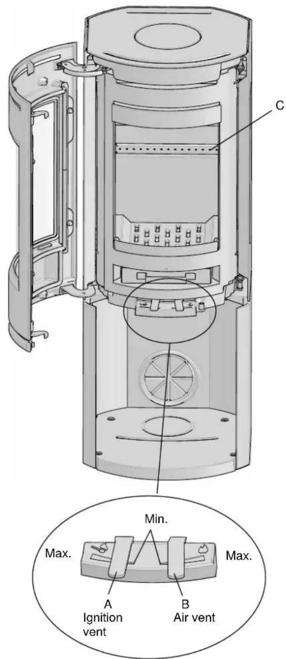
C Max. Min. A Ignition vent B Air vent Max.The Jøtul F 130 is equipped with the following operating options:
Ignition vent (A)
Pushed to the left: Maximum
Pushed to the right: Minimum
Air vent (B)
Pushed to the left:: Minimum
Pushed to the right: Maximum
Stacking height (C) for logs (the holes must not be covered).
4.7 Use
- Push the ignition vent all the way to the left (fig. 28). Open the air vent (fig. 28) by pushing it to the right. (Use a glove, for example, as the handle can become hot.).
Fig. 29
natural_image
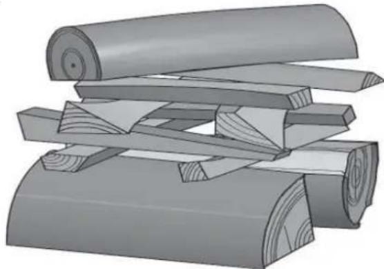
Stacked wood logs with visible grain patterns and wooden edges (no text or symbols)- Place two medium sized logs in/out on each side of the base. N.B. In order to avoid sooting on the glass, it is important that the log is not placed adjacent to the glass on the product.
- Crumple some newspaper (or birch bark) between these and add some kindling wood in a criss-cross pattern on top and light the newspaper.
- Gradually increase the size of the fire, but the wood should not be stacked higher than the horizontal holes on the back burn plate. See fig. 28 C.
• Finally, place a medium-sized log on the top of the pile. - Place 2 or 3 briquettes or kindling sticks under the top layer of kindling and light the fire.
- NB: The maximum height of the pile of the wood should be just below the horizontal holes. The holes must not be covered.
- Check that the afterburning (secondary combustion) starts. This is best indicated by yellow, flickering flames under the baffle.
- Then regulate the rate of combustion to the desired level of heating by adjusting the air vent (fig. 28).
- Close the stove door. It must always be closed when the fire is lit.
Adding fi rewood
Stoke the stove frequently but only add small amounts of fuel at a time. If the stove is filled too full, the heat created may cause extreme stress in the chimney. Add fuel to the fire in moderation. Avoid smouldering fires as this produces the most pollution. The fire is best when it is burning well and the smoke from the chimney is almost invisible.
4.7 Danger of overheating
The fi replace must never be used in a manner that causes overheating.
Overheating occurs when there is too much fuel and/or too much air so that too much heat develops. A sure sign of overheating is when parts of the fi replace glow red. If this happens, reduce the air vent opening immediately.
Seek professional advice if you suspect that the chimney is not drawing properly (too much/too little draught). For further information, see «4.4 Chimney and flue pipe»
5.2 Ash removal
Jøtul F 130 has an ash pan which makes it easy to remove the ashes.
- Only remove ashes when the fi replace is cold.
- Push/pull the handle for the ash grate/ignition vent out and in several times so that the ashes fall down into the ash pan. Use something like a glove to grab the handle on the ash pan.
- Make sure that the ash pan doesn't fill up so high that it keeps ash from coming through the grate into the pan.
5.0 Daily use
Odours when using the fireplace for the first time
When the fireplace is used for the first time, it may emit an irritating gas which may smell slightly. This happens because the paint dries. The gas is not toxic but the room should be thoroughly ventilated. Let the fire burn with a high draught until all traces of the gas have disappeared and no smoke or odours can be detected.
Heating advice
NB: Logs that have been stored outdoors or in a cold room should be brought indoors 24 hours before use to bring them up to room temperature.
There are various ways of heating the stove but it is always important to be careful about what you put in the stove. See the section on "Wood quality".
Wood quality
By quality wood we mean most well-known types of wood such as birch, spruce and pine.
The logs should be dried so that the moisture content is no more than 20%.
To achieve this, the logs should be cut during the late winter. They should be split and stacked in a way that ensures good ventilation. The wood stacks should be covered to protect the logs from rain. The logs should be brought indoors during early autumn and stacked/stored for use in the coming winter.
Be especially careful never to use the following materials as fuel in your fi replace:
• Household rubbish, plastic bags, etc.
- Painted or impregnated timber (which is extremely toxic).
• Laminated wooden planks.
- Driftwood
These may harm the product and are also pollutants.
NB: Never use petrol, paraffi n, methylated spirit or similar liquids to light the fi re. You may cause serious injury to yourself and damage to the product.
ENGLISH
Jøtul F 130 has a nominal heat output of ca. 4,7 kW. Use of wood, with nominal heat emission: Approx. 1,25 kg/h. Another important factor for proper fuel consumption is that the logs are the correct size. The size of the logs should be:
Kindling:
Length: Max. 20 cm
Diameter: 2 - 4 cm
Amount per fi re: 6 - 8 stk.
Firewood (split logs):
Diameter: Approx. 8 cm
Intervals for adding wood: Approximately every 45 minutes
Amount per load: 1,25 kg (nominal heat output)
Size of the fire: 2 pieces
Amount per load: 1,26 kg
Nominal heat output is achieved when the ignition vent is open approximately 30 % (fig. 28). Max. heat output is achieved when the air vent is open 100 %.
6.0 Maintenance
6.1 Cleaning the glass
The product is equipped with an air wash for the glass. Air is sucked in through the air vent on the top of the product and down along the inside of the glass.
However, some soot will always stick to the glass, but the quantity will depend on the local draught conditions and adjustment of the air vent. Most of the soot layer will normally be burned off when the air vent is opened all the way and a fire is burning briskly in the fi replace.
Good advice! For normal cleaning, moisten a paper towel with warm water and add some ash from the burn chamber. Rub it over the glass and then clean the glass with clean water. Dry well. If it is necessary to clean the glass more thoroughly we recommend using a glass cleaner (follow the instructions on the bottle).
6.2 Cleaning and soot removal
Soot deposits may build up on the internal surfaces of the fi replace during use. Soot is a good insulator and will therefore reduce the fireplace's heat output. If soot deposits accumulate when using the product, they can be easily removed by using a soot remover.
In order to prevent a water and tar layer from forming in the fireplace you should regularly allow the fire to burn hot in order to remove the layer. An annual internal cleaning is necessary to get the best heating effect from the product. It is a good idea to do this in connection with the sweeping of the chimney and flue pipes.
6.3 Sweeping of fl ue pipes to the chimney
On certain free-standing fireplaces the top plate can be lifted off and the pipe swept through the top.
Otherwise, flue pipes must be swept through the flue pipe sweeping hatch or through the product's door opening. Then, the baffi e must be removed.
6.4 Inspection of the fi replace
Jøtul recommends that you personally inspect your fi replace carefully after sweeping/cleaning. Check all visible surfaces for cracks. Also check that all joints are sealed and that the gaskets are in the correct position. Any gaskets showing signs of wear or deformation must be replaced.
Thoroughly clean the gasket grooves, apply ceramic glue (available from your local Jøtul dealer), and press the gasket well into place. The joint will dry quickly.
6.5 Exterior maintenance
Painted products may change colour after several years usage. The surface should be cleaned and brushed free of any loose particles before new paint is applied.
Important! Never place anything on the top plate of the stove. This could cause permanent damage to the paint or enamel.
7.0 Service
Any unauthorised modifications to the product are prohibited! Only original spare parts may be used!
7.1 Service / replacing parts of the burnchamber
Note! If you use tools, be aware that the vermiculite plates may be damaged by rough treatment.
Fig. 30
text_image
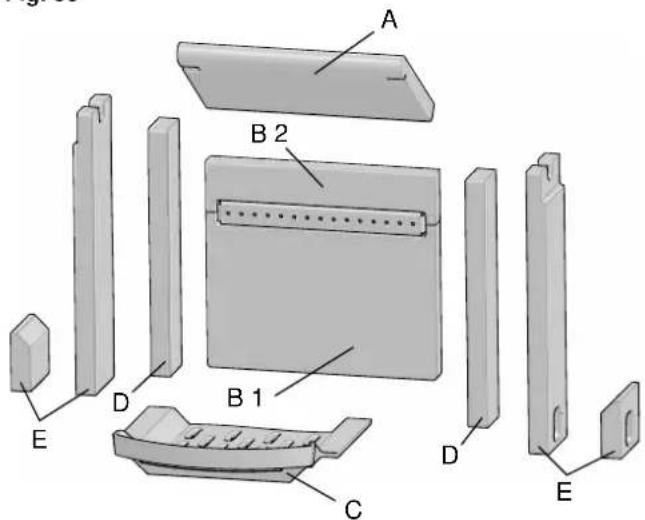
A B 2 B 1 D E C D E- Baffle: Lift the rear edge of the baffle (A) up and down and twist it out of the burn chamber.
- Lift up the ash grate (C) and remove it from the burn chamber.
- Remove the side burn plate(s) (D).
- Remove the side burn plate(s) (E) (the tall side burn plates are for models without side windows, while the short ones are for models with side windows).
- Remove the rear burn plate (B).
7.2 Replacing glass and gaskets in the door
Fig. 31
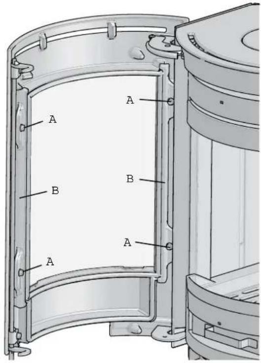
text_image
A B A B A- Remove the four screws (A) that attach the brackets (B) to the door.
- Remove the brackets.
Fig. 32

natural_image
Technical diagram of a door frame with an arrow pointing to a component, labeled 'A' (no text or symbols beyond label)- Carefully lift the glass door (A) out.
ENGLISH
Fig. 33
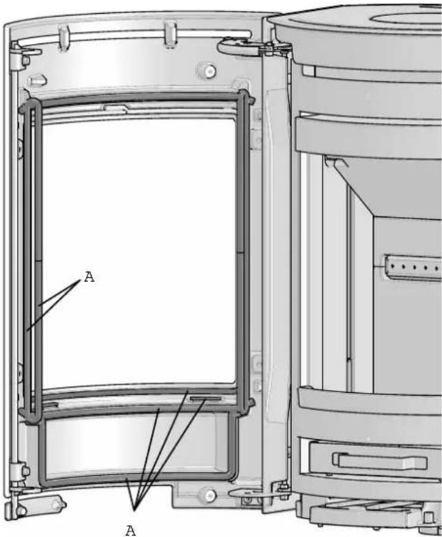
text_image
A A- Remove the gaskets (A) from the door. Thoroughly clean the gasket groove and glue new gaskets into place.
- Once all damaged gaskets have been replaced, refi t the door glass (fig. 32) and the brackets (fig. 31).
8.0 Optional equipment
8.2 Outside air connection
∅ 100mm - Art. no. 51012164
9.0 Operational problems - troubleshooting
Poor draught
- Check the length of the chimney and that it complies with national laws and regulations. (See also «2.0 Technical data» and «4.0 Installation» (Chimney and flue pipe) in the installation manual for information.)
- Make sure that the minimum cross section on the chimney is according to «2.0 Technical data» in the installation manual.
- Make sure that there is not anything preventing the smoke gasses from escaping: branches, trees, etc.
- Upon suspicion of excessive/poor draught in the chimney, seek professional help for measurement and adjustment.
The fi re extinguishes after a while
- Make sure that the firewood is sufficiently dry.
- Find out whether there is negative pressure in the house, close mechanical fans and open a window close to the fi replace.
- Check that the air vent is open.
- Check that the fl ue outlet is not clogged by soot.
Unusual amount of soot accumulates on the glass
Some soot will always stick to the glass, but the quantity depends on:
- Moisture in the fuel.
- The local draught conditions.
- Air vent opening.
Most of the soot will normally burn off when the air vent is opened all the way and a fire is burning briskly in the fireplace. (See «6.1 Cleaning the glass - good advice».)
10.0 Recycling
9.1 Recycling packaging
Your fi replace is delivered with the following packaging:
- A wooden pallet that can be cut up and burned in the fi replace.
- Cardboard packaging that should be taken to a local recycling facility.
- Plastic bags that should be taken to a local recycling facility.
9.2 Recycling the fi replace
The fi replace is made of:
• Metal that should be taken to a local recycling facility.
- Glass that should be disposed of as hazardous waste. The glass in the fi replace must not be placed in a regular source segregation container.
- Vermiculite burn plates that can be disposed of in regular waste containers.
11.0 Guarantee terms
1. Our guarantee covers:
Jøtul AS guarantees that the external cast-iron parts are free from defects in materials or manufacturing at the time of purchase. You may extend the guarantee on the external cast-iron parts to 25 years from the date of delivery by registering the product on jotul.com, and print out the extended guarantee card within three months of purchase. We recommend that the guarantee card be kept together with the receipt. Jøtul AS also guarantees that steel plate parts are free from defects in materials or manufacturing at the time of purchase for a period of 5 years from the date of delivery.
The guarantee applies on the condition that the stove has been installed by a qualified installer in accordance with applicable laws and regulations and Jøtul's installation and operating instructions. Repaired products and replacement items are guaranteed within the original guarantee period.
2. The guarantee does not cover:
2.1. Damage to consumables such as burn plates, fire grates, flue baffles, gaskets and similar as these deteriorate over time due to normal wear and tear.
2.2. Damage caused as a result of improper maintenance, overheating, use of unsuitable fuel (e.g of unsuitable fuel are, but not limited to driftwood, impregnated wood, plank offcuts, chipboard) or too moist / wet wood.
2.3. Installation of optional extras for the purpose of rectifying local draught conditions, air supply or other circumstances beyond Jøtul's control.
2.4. Cases involving alterations / modifications to the fireplace without Jøtul's consent or the use of non-original parts.
2.5. Damage caused during storage at a distributor, transport from a distributor or during installation.
2.6. Products sold by unauthorized sellers in areas where Jøtul operates a selective distribution system.
2.7. Associated cost (e.g. but not limited to, transport, manpower, travel) or indirect damages.
Pellets stoves, glass, stone, concrete, enamel and paint fi nish (e.g. but not limited to chipping, cracking, bubbling or discolouration and crazing) are applicable to the national legislation governing the sale of consumer goods. This guarantee is valid for purchases made within the territory of the European Economic Area. All guarantee inquiries must be addressed to your local authorized Jøtul dealer within a reasonable amount of time, which shall not be later than 14 days from the date on which the fault or defect fi rst became apparent. See list of importers and dealers on our web site www.iotul.com.
If Jøtul is unable to meet the obligations outlined in the above guarantee terms, Jøtul will offer a replacement product with a similar heating capacity free of charge.
Jøtul reserve the right to decline of any replacement of parts or service in the event that the guarantee is not registered online. This guarantee does not affect any rights under applicable national legislation governing the sale of consumer goods. The national complaint right applies from the purchase date and only in exchange for a receipt / serial number.
FRANCAIS
Sommaire
Jøtul F 130 Series
Fig. 1d
natural_image
Technical line drawing of a mechanical assembly with spring-loaded components and a housing (no text or symbols)natural_image
Architectural cross-section diagram showing wall and floor layers with no text or symbolsnatural_image
Technical line drawing of a mechanical assembly with no visible text or symbolsnatural_image
Technical line drawing of a mechanical assembly with spring-loaded components and a vertical component (no text or symbols)4.0 Installation
natural_image
Technical illustration of a mechanical device with labeled components A and B, mounted on a bench (no text or symbols beyond labels)text_image
Technical diagram of a device with labeled components and dashed lines indicating assembly or assembly stepsnatural_image
3D technical drawing of a mechanical part with a hammer and labeled component (no text or symbols beyond labels)natural_image
Technical line drawing of a mechanical device with labeled component A (no text or symbols beyond labels)natural_image
Technical illustration of a portable water heater with labeled component A (no text or symbols beyond labels)natural_image
Technical diagram of a mechanical component with labeled section A (no readable text or symbols)natural_image
Technical diagram of a mechanical assembly with labeled components (no readable text or symbols)natural_image
3D mechanical assembly diagram showing a base with a gavel and labeled component A (no text or symbols beyond labels)natural_image
3D technical diagram of a mechanical device with labeled component A and rotation arrow (no readable text or symbols)natural_image
3D mechanical component diagram showing a cylindrical part with a labeled component A and an arrow indicating upward motion (no text or symbols present)natural_image
Diagram of a cylindrical container with two labeled points A and a circular hole, connected by lines (no text or symbols beyond labels)- Desserrez les quatre vis (A).
Fig. 20
natural_image
Technical diagram of a device showing front and side views with labeled component B (no text or symbols beyond label)natural_image
3D diagram of a mechanical part with labeled section A and a hand tool, showing mounting holes and a dashed line indicating a measurement or alignment.text_image
Technical diagram showing a device with labeled components A and B, including a pliers and internal compartments.text_image
Technical diagram of a mechanical device with labeled components A, B, C, D and directional arrows indicating assembly or movement.text_image
Technical diagram of a mechanical device with labeled components A, B, and Dtext_image
Exploded view diagram of a device showing internal components labeled A, B, C, D with arrows indicating assembly or component alignment.natural_image
3D diagram of a mechanical component with labeled parts A and B, showing a cylindrical shaft and circular opening (no text or symbols beyond labels)natural_image
3D rendered image of stacked cylindrical objects with layered surfaces (no text or symbols)(nominal heat output)
Nombre de bûches à
natural_image
Technical diagram of a mechanical assembly with a labeled component (A), showing internal components and a black arrow pointing to a specific part (no text or symbols present)NOx at 13% O₂: 148 mg / Nm³
OGC @ 13 % O₂: 79 mg /Nm³
natural_image
Architectural cross-section diagram showing wall and floor construction with no visible text or symbolsnatural_image
Architectural cross-section diagram showing wall and floor construction with no visible text or symbolsnatural_image
Technical cross-section diagram of a structural joint or pipe system (no text or labels visible)natural_image
Technical line drawing of a mechanical assembly with spring-loaded components and a side view (no text or symbols)NEDERLANDS
4.0 Installatie
natural_image
Technical illustration of a mechanical device with labeled components A and B, mounted on a bench (no text or symbols beyond labels)text_image
Technical diagram of a device with labeled components and dashed lines indicating assembly or assembly stepsnatural_image
3D technical drawing of a mechanical part with a hatched tool and labeled point A (no text or symbols beyond label)natural_image
Technical line drawing of a mechanical device with labeled component A (no text or symbols beyond label)natural_image
3D technical illustration of a JOTNIL device with labeled components (no readable text or symbols)natural_image
Technical diagram of a mechanical component with labeled section A (no readable text or symbols)natural_image
Technical diagram of a mechanical assembly with labeled components and directional arrows (no readable text or symbols)natural_image
3D mechanical assembly diagram showing a base with a gavel and labeled component A (no text or symbols beyond labels)natural_image
3D mechanical assembly diagram showing a press or lift mechanism with labeled component A and directional arrow (no text or symbols beyond labels)natural_image
3D mechanical component diagram showing a cylindrical part with a labeled component A and an arrow indicating direction (no text or symbols beyond label)text_image
Technical diagram showing a mechanical component with labeled parts A and B, and a downward arrow indicating a process or assembly.natural_image
Diagram of a cylindrical device with two labeled points A, showing internal structure and connection points (no text or symbols beyond labels)natural_image
Technical diagram showing a door frame with internal compartments and a separate view of the door (no text or symbols present)natural_image
3D diagram of a mechanical part with labeled section A and a hand gesture (no text or symbols beyond labels)text_image
Technical diagram showing a 3D mechanical assembly with labeled components A and B, including a directional arrow indicating movement or assembly.text_image
Technical diagram of a mechanical device with labeled components A, B, C, D and directional arrows indicating assembly or movement.text_image
Technical diagram of a mechanical device with labeled components A, B, and Dtext_image
Exploded view diagram of a device showing internal components labeled A, B, C, D and part layout with arrows indicating assembly or inspection.natural_image
3D diagram of a mechanical component with labeled parts A and B, showing a cylindrical shaft and circular opening (no text or symbols beyond labels)Pushed to the left:: Minimum
Pushed to the right: Maximum
natural_image
Stacked wood logs with visible grain patterns and wooden shingles (no text or symbols)natural_image
Technical diagram of a door frame with an arrow pointing to a component, labeled 'A' (no text or symbols beyond label)Quality control of stoves and fireplaces
Jøtul pursue a policy of constant product development. Products supplied may therefore differ in specification, colour and type of accessories from those illustrated and described in the brochure.
Jøtul AS has a quality system that conforms to NS-EN ISO 9001 for product development, manufacturing, and distribution of stoves and fireplaces. This policy gives our customers quality and safety piece of mind as a result of Jøtul's vast experience dating back to when the company first started in 1853.