F 263 - Heating Jøtul - Free user manual and instructions
Find the device manual for free F 263 Jøtul in PDF.
| Product type | Wood stove |
| Brand | Jøtul |
| Model | F 263 |
| Fuel | Wood only |
| Nominal heat output | 5.9 kW |
| Efficiency | 83 % (depending on version) |
| CO emissions (13 % O₂) | 0.06 % |
| Flue gas temperature | 270 °C |
| Recommended draught | 12 Pa |
| Maximum log length | 33 cm |
| Connection flue diameter | 150 mm |
| Weight | Approx. 140 kg |
| Finish | Black paint |
| Flue outlet | Top or rear |
| Operating mode | Intermittent |
| Combustion chamber material | Cast iron and vermiculite |
| Optional equipment | Soapstone top, soapstone cladding, fan |
| Warranty | On external cast iron parts (material/manufacturing defect) |
Frequently Asked Questions - F 263 Jøtul
User questions about F 263 Jøtul
0 question about this device. Answer the ones you know or ask your own.
Ask a new question about this device
Download the instructions for your Heating in PDF format for free! Find your manual F 263 - Jøtul and take your electronic device back in hand. On this page are published all the documents necessary for the use of your device. F 263 by Jøtul.
USER MANUAL F 263 Jøtul
Installation manual with technical data
1.0 Relationship to the authorities 2
2.0 Technical data 2
3.0 Safety
4.0 Installation 5
5.0 Daily use 11
6.o Service 13
7.0 Maintenance
8.o Optional Equipment 15
9.o Warranty
1.0 Relationship to the authorities
Installation of a fireplace must be according to local codes and regulations in each country.
All local regulations, including those that refer to national and European standards, shall be complied with when installing the product.
4 Before use read the Installation and Operating Instructions carefully. Prior to using the product the installation must be inspected by a qualified person.
A name plate of heat-resistant material is affixed to the product on the inside of the base. This contains information about identification and documentation for the product.
15 2.o Technical data
| Jøtul F 262 | Jøtul F 263 | |
| Material: | Cast iron | Cast iron |
| Finish: | Black paint | Black paint |
| Fuel: | Wood | Wood |
| Log length, max: | 33 cm | 33 cm |
| Flue outlet: | Top/rear | Top/rear |
| Flue pipe dimension: | Ø150 mm, 177 cm | Ø150 mm, 177 cm |
| cross section | cross section | |
| Weight: | approx 140 kg | approx 140 kg |
| Weight, soapstone set: | approx 80 kg | approx 80 kg |
| Weight, steel sides: | approx 20 kg | approx 20 kg |
| Weight, soapstone top | ||
| (Optional extra): | approx 20 kg | approx 20 kg |
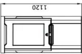
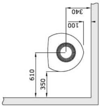
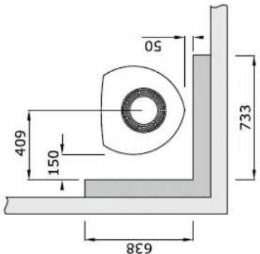
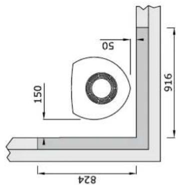
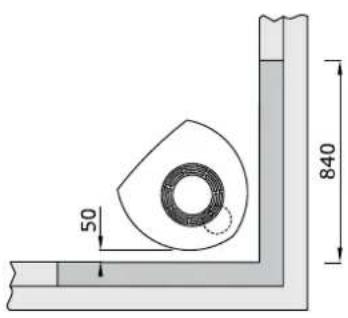
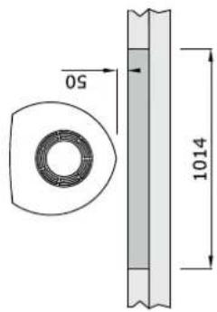
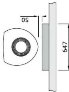
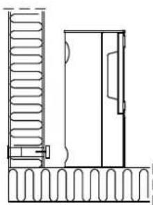
| Dimensions, distances: | See fig. 1a | See fig. 1a |
Technical data according to EN 13240
| Jøtul F 262 | Jøtul F 263 | |
| Jøtul F 262 S | Jøtul F 263 S | |
| Nominal heat output: | 5 kW | 5 kW |
| Flue gas mass flow: | 4,5 g/s | 5,0 g/s |
| Recommended chimney draught: | 12 Pa | 12 Pa |
| Efficiency: | 83%@5,9 kW | 82%@5,9 kW |
| CO emission (13% O2): | 0,06% | 0,10% |
| CO emission (13% O2): | 792 mg/Nm3 | 1242 mg/Nm3 |
| Flue gas temperature: | 270°C | 260°C |
| Operational type: | Intermittent | Intermittent |
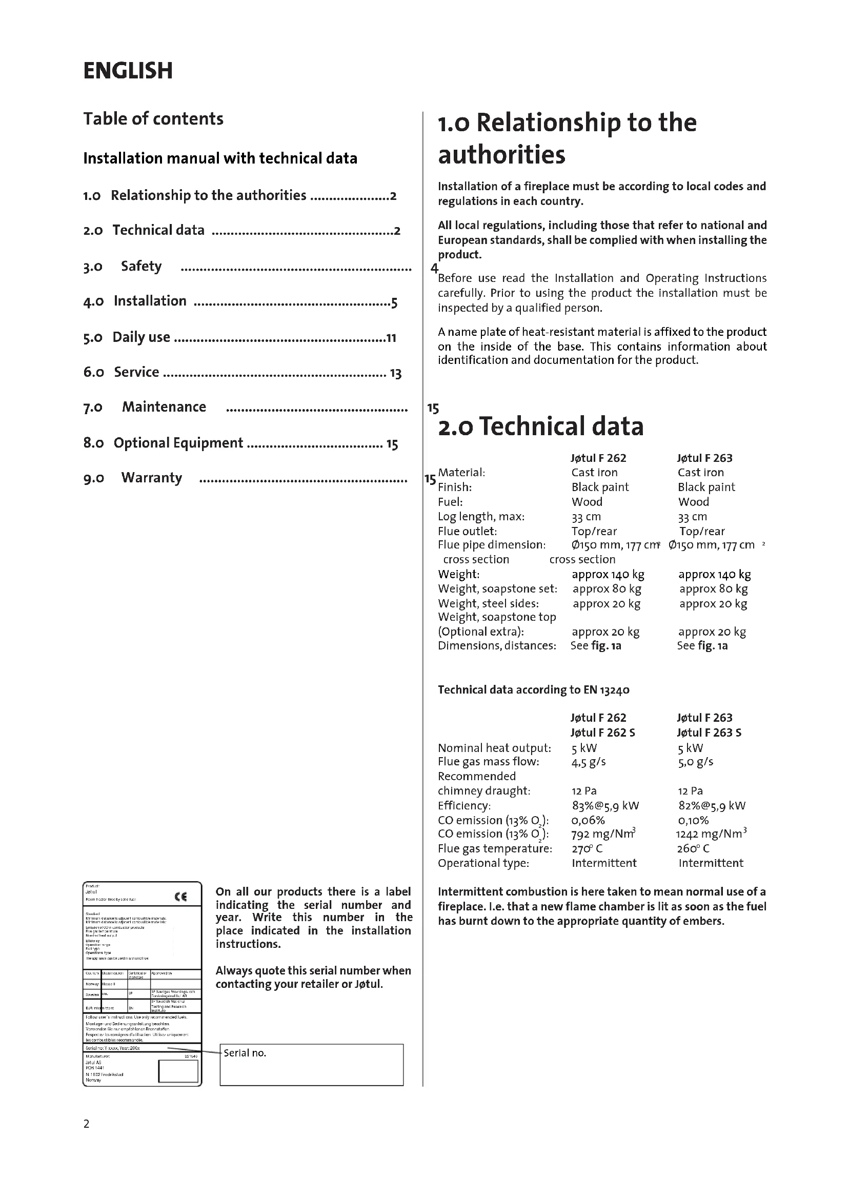
On all our products there is a label indicating the serial number and year. Write this number in the place indicated in the installation instructions.
Always quote this serial number when contacting your retailer or Jøtul.
Serial no.
Intermittent combustion is here taken to mean normal use of a fireplace. i.e. that a new flame chamber is lit as soon as the fuel has burnt down to the appropriate quantity of embers.
Jøtul F 262 / F 263
Fig. 1
Produkt:Jotul F 263
Min. distance to combustible wall protected by firewall:
Min. distance to combustible wall:
Cast iron top
Soap stone top
Integrated
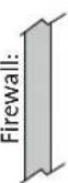
Combustible wall:
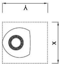
Min.measurements floor plate X,Y =
According to national standards
The following is an overview of the various methods used to calculate the P values for the 1970s and 1980s.
900085-P03
With semi-insulated chimney / covered flue pipe down
towards the product.

ENGLISH
Air supply
The outside air connection may be fitted directly to the product through:
- Through a flexible supply hose from the outside/chimney (only if the chimney has its own duct for external air) and to the product's outside air connector.
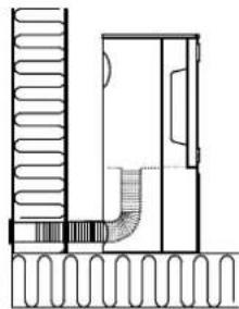
Fig. 2a, through an outside wall
Fig. 2b, through the floor and ground plate
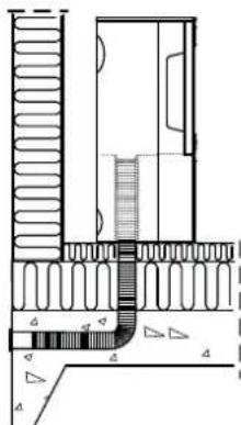
Fig. 2c, through the floor and basement
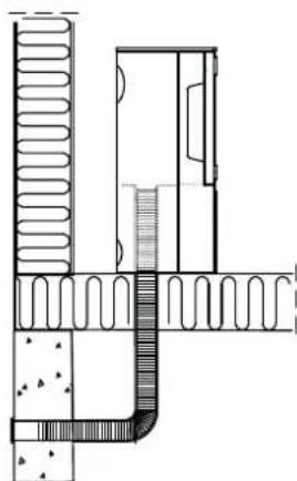
Fig. 2d, indirectly through an outside wall
3.0 Safety
NB! To guarantee optimal performance and safety, Jøtul stoves must be fitted by a qualified installer.
Any modifications to the product by the distributor, installer or consumer may result in the product and safety features not functioning as intended. The same applies to the installation of accessories or optional extras not supplied by Jotul. This may also be the case if parts that are essential to the functioning and safety of the fireplace have been disassembled or removed.
In all these cases, the manufacturer is not responsible or liable for the product and the right to make a complaint becomes null and void.
3.1 Fire Prevention Measures
There is a certain element of danger every time you use your fireplace. The following instructions must therefore be followed:
- The minimum safety distances when installing and using the fireplace are given in fig. 1a.
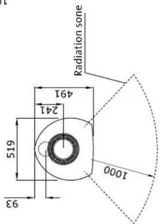
- Ensure that furniture and other flammable materials are not too close to the fireplace. Flammable materials should not be placed within 1 meter in front of the fireplace.
- Allow the fire to burn out. Never extinguish the flames with water.
- The fireplace becomes hot when lit and may cause burns if touched.
- Only remove ash when the fireplace is cold. Ash can contain hot embers and should therefore be placed in a non-flammable container.
- Ash should be placed outdoors or be emptied in a place where it will not present a potential fire hazard.
In case of chimney fire:
- Close all hatches and vents.
- Keep the firebox door closed.
- Check the loft and cellar for smoke.
Call the fire service. - Before use after a fire an expert must check the fireplace and the chimney in order to ensure that it is fully functional.
3.2 Floor
Foundations
Ensure that the floor is strong enough for the fireplace. See «2.0 Technical data» for weights. It is recommended that flooring which is not fastened to the foundations – so-called floating flooring – is removed during installation.
Combustible floor protection
The product has integrated floor protection and may therefore be placed directly on a wodden floor.
Any flooring made of combustible material, such as linoleum, carpets, etc. should be removed from under the floor plate.
Requirements for protection of inflammable floors in front of the fireplace
The plate must be in accordance with national laws and regulations.
Contact your local building authority regarding restrictions and installation requirements.
3.3 Walls (fig. 1a)
Distance to wall made of combustible material
Distance to wall with insulated flue pipe: See fig. 1a.
Distance to walls covered by a firewall
Contact your local building authority regarding restrictions and installation requirements.
Firewall requirement
The firewall must be at least 100 mm thick and be made of brick, concrete-stone or light concrete. Other materials and constructions with satisfactory documentation may also be used.
Distance to non combustible walls
By non combustible one means a non load-bearing wall of solid brickwork/concrete.
Contact your local building authority regarding restrictions and installation requirements.
3.4 Ceiling
If the ceiling above the fireplace is made of a combustible material, the minimum distance between the fireplace and ceiling must be 1000mm .
4.o Installation
The product is delivered in at least 2 packing cases.
N.B. Check that the fireplace is free of any damage prior to commencing installation.
The product is heavy! Make sure you have assistance when erecting and installing the fireplace.
4.1 Chimneys and flue pipes
- The fireplace can be connected to a chimney and flue pipe approved for solid fuel fired appliances with flue gas temperatures specified in «2.0 Technical data».
- The chimney's cross-section must be at least as big as the flue pipe's cross-section. See «2.0 Technical data» when calculating the correct chimney cross-section.
- Several solid fuel fired appliances can be connected to the same chimney if the chimney's cross-section is sufficient. Contact your local building authority regarding restrictions and installation requirements.
Before making a hole in the chimney the fireplace should be test-mounted in order to correctly mark the position of the fireplace and the hole in the chimney. See fig. 1 for minimum dimensions. -
Connection to the chimney must be carried out in accordance with the installation instructions from the supplier of the chimney.
-
Ensure that the flue pipe is inclined all the way up to the chimney.
- Use a flue pipe bend with a sweeping hatch that allows it to be swept.
Be aware of the fact that it is particularly important that connections have a certain flexibility in order to prevent movement in the installation leading to cracks.
N.B. A correct and sealed connection is very important for the proper functioning of the product.
Chimney draught; See «2.o Technical data». If the draught is too strong you can install and operate a flue damper to control the draught.
4.2 Selfclosing doormechanism
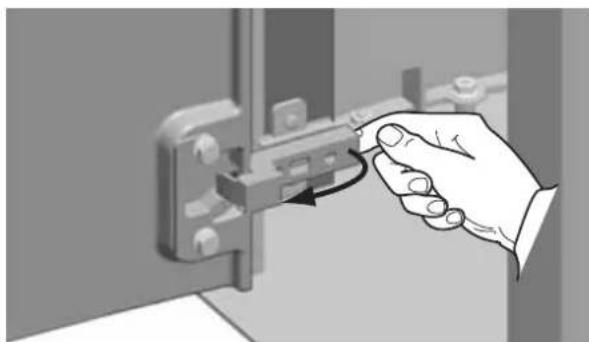
The product is delivered with a selfclosing doormechanism. If wanted this can be removed.
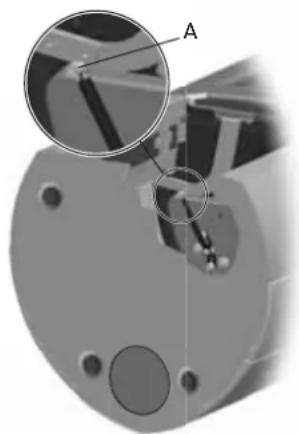
Fig. 3
- Unscrew the screw and nut (Fig. 3 A).
- Unhook and remove the spring.
4.3 Leveling the fireplace
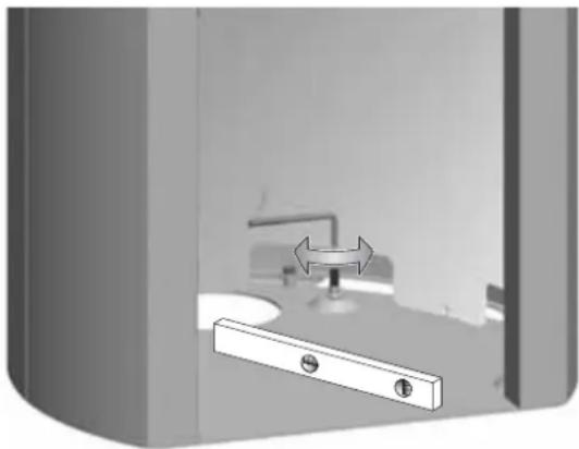
Fig. 3b
ENGLISH
4.4 Fitting the flue pipe with the rear outlet
The product is supplied from the factory with the smoke outlet fitted for the top outlet.
NB! Proceed as follows for installation with a rear outlet:
When installing with soapstone side panels, the rear plate (Fig. 4 B) has to be prepared before the product is placed on its final position.
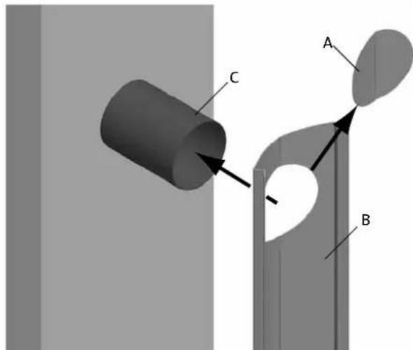
Fig. 4
- Knock out the removable cover plate (Fig. 4 A) in the rear plate (Fig. 4 B).
- Hang the rear plate gently on the flue pipe (Fig. 4 C).
- Place the product in the correct position. (See Fig. 1a).
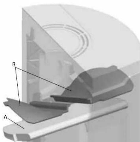
Fig.5
- Remove the baffle plate and exhaust deflectors (Fig. 5 B).
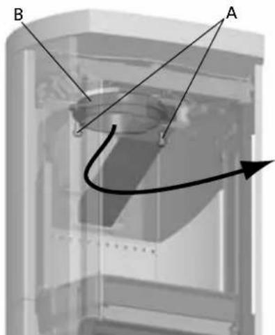
Fig. 6
- Unscrew the screws (Fig. 6 A) and remove the smoke outlet (Fig. 6 B) from the inside of the burn chamber.
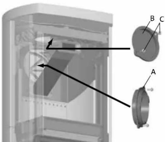
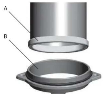
Fig. 7
- Unscrew the screws (Fig. 7C) and remove the cover (Fig. 7B) from the rear outlet from the inside of the burn chamber.
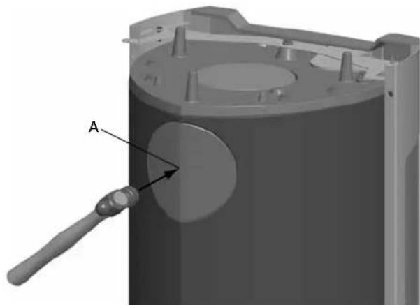
Fig 8
- Knock out the removable covers (Fig. 8A).
-
Attach the smoke outlet (Fig. 7A) on the inside of the burn chamber where the cover was.
-
Install the cover (Fig. 7B) where the smoke outlet was. Fig. 11
- Refit the exhaust deflectors (Fig. 5 B) and the baffle plate (Fig. 5 A).
Fig. 9
1. Place the gasket (Fig. 9 A) from the bag of screws around the edge of the flue pipe and push it into the smoke outlet (Fig. 9 B).
4.5 Mounting side panels
Steel side panels
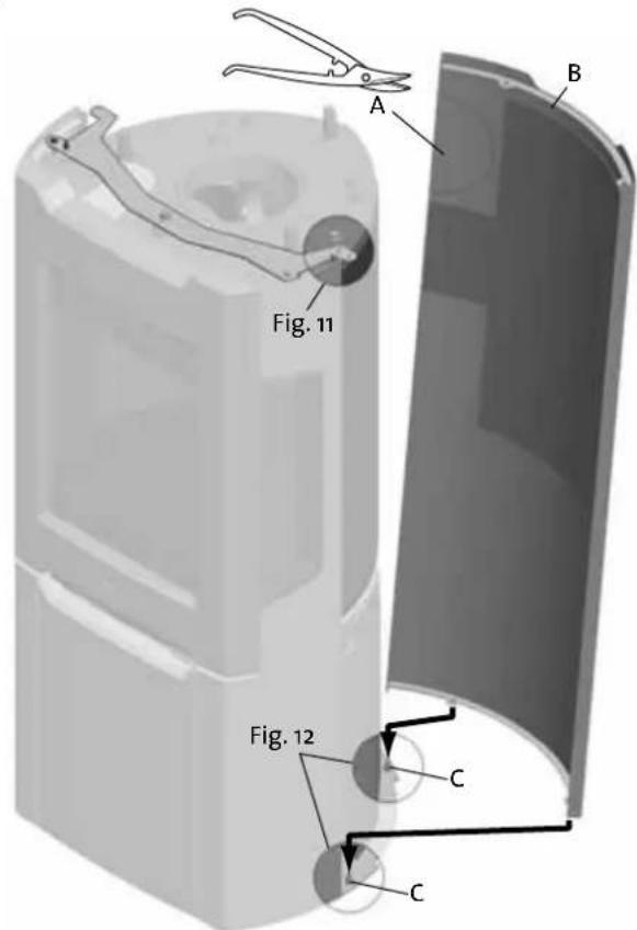
Fig. 10
- If rear outlet: Use proper tool to remove the cover plate (Fig. 10 A) in the side panel (Fig. 10 B).
- Lift the side panel and lower it over the bolts (Fig. 10 C and Fig. 12).
- Mount the other steel side panel the same way.
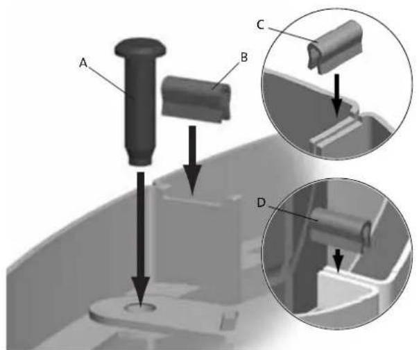
- Mount the pins (Fig. 11 A) and the clips (Fig. 11 B).
- Join the two side panels together using a clip (Fig. 11C).
- If rear outlet: Mount an extra clip in the lower part of the opening (Fig. 11 D).
Fig. 12
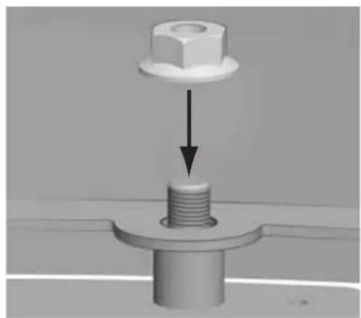
1. Mount the nuts from inside of the base.
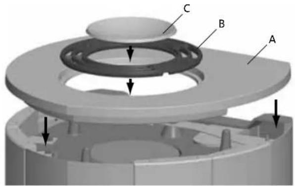
Fig. 13
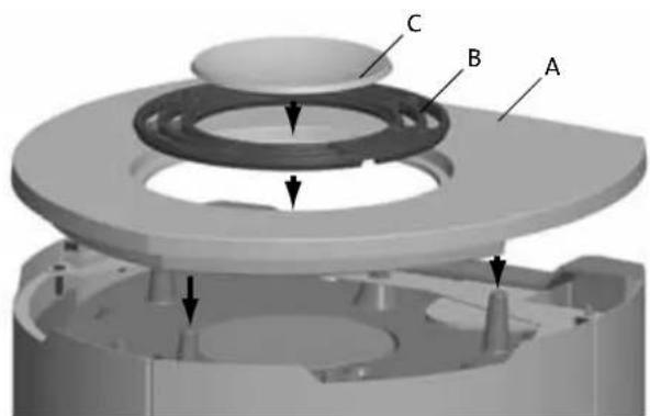
1. Place the top plate (Fig. 13 A), air grate (Fig. 13 B) and bowl (Fig. 13 C).
ENGLISH
If soapstone top:
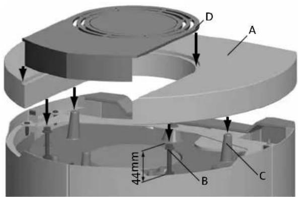
Fig. 14
- Replace the screws with bolt and nut (fig. 14 B) provided.
- Place the soapstone top (Fig. 14 A) on the screws (Fig. 14 B) and the guiding warts (Fig. 14 C).
- Adjust the screws (Fig. 14B) until the soapstone top is level.
- Place the steel cover (Fig. 14 D).
Soapstone side panels
Important!
Bear in mind that the stones may be damaged if they are handled roughly. Installation should be carried out by a qualified person.
With rear smoke outlet the rear plate has to be prepared as shown in figure 4.
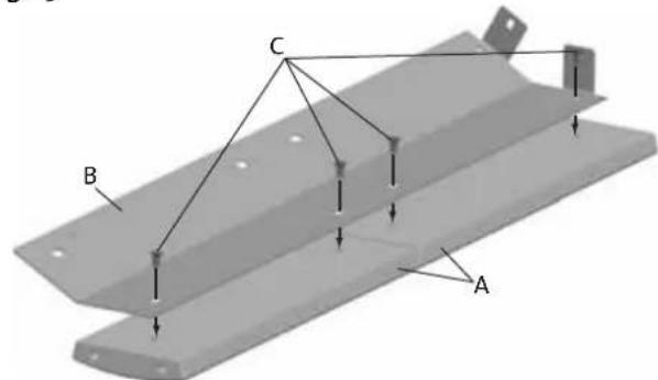
Fig. 15
- Place 2 soapstones (Fig. 15 A) carefully on the floor.
- Mount the bracket (Fig. 15 B) with 4 screws (Fig. 15 C). Do not tighten the screws yet.
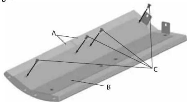
Fig. 16
- Mount the next 2 soapstones (Fig. 16 A) to the bracket (Fig. 16 B) with 4 screws (Fig. 16 C). Do not tighten the screws yet.
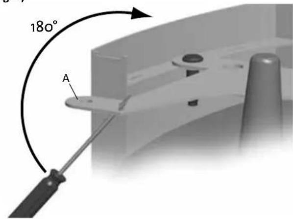
Fig. 17
- Bend up the outer part (Fig. 17 A) of the bracket.
If rear smoke outlet:
Place the rear plate (Fig. 4 B) and mount it temporarily as shown in figure 21.
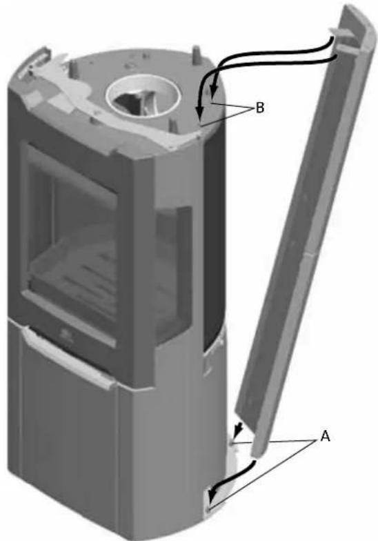
Fig. 18
- Carefully raise the soapstone side panel.
- Adjust the position of the soapstone and tighten the screws.
- Lift the soapstone panel and carefully lower it over the bolts (Fig. 18 A).
- Then push the upper section of the soapstone side panel on to the burn chamber (Fig. 18 B).
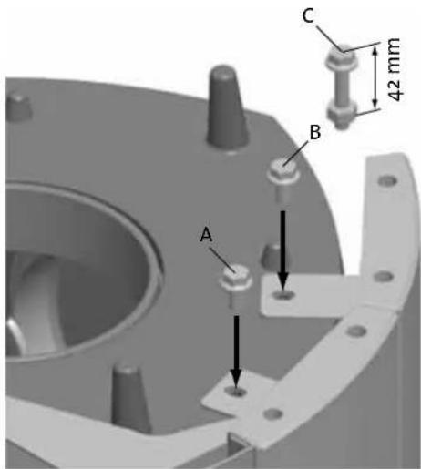
Fig. 19
- Mount the soapstone side panel to the burn chamber with the screws (Fig. 19 A and B).
- If soapstone top: Replace the screws (Fig. 19 B) with the bolts and nuts (Fig. 19 C) provided.
- Mount the other soapstone side panel the same way.
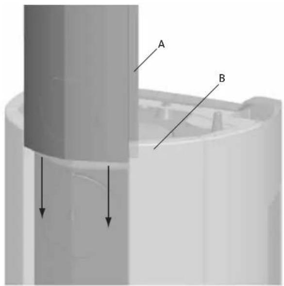
Fig. 20
1. Lift the rear plate (Fig. 20 A) and slide it down between the soapstone side panels (Fig. 20 B).
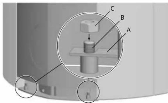
Fig. 21
- Lower the rear plate (Fig. 21 A) onto the bolts (Fig. 21 B).
- Mount nuts from inside of the base (Fig. 21C).
ENGLISH
Fig. 22
1. Place the top plate (Fig. 22 A), air grate (Fig. 22 B) and bowl (Fig. 22 C).
If soapstone top:
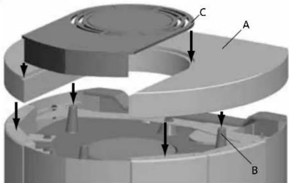
Fig. 23
- Place the soapstone top (Fig. 23 A) on the guiding warts (Fig. 23 B).
- Place the steel cover (Fig. 23C).
4.6 Mounting the fireplace set
Fig. 24
1. Mount the bracket (Fig. 24 A) to the door with the screws (Fig. 24 B).
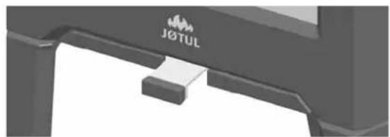
4.7 Control of functions
When the product is set up, always check the control functions. These shall move easily and function satisfactorily.
The product is equipped with one handle. This handle controls both the ignition vent and the air vent.
- Pulled out completely (the label visible): Ignition.
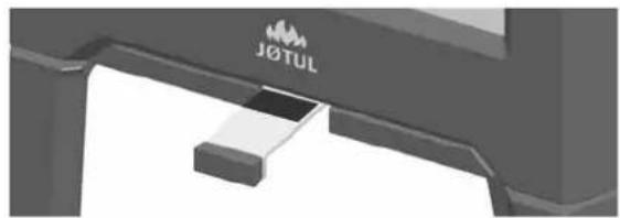
- Pushed in (the label not visible): Air vent.
5.o Daily use
Odours when using the fireplace for the first time
When the fireplace is used for the first time, it may emit an irritating gas which may smell slightly. This happens because the paint dries. The gas is not toxic but the room should be thoroughly ventilated. Let the fire burn with a high draught until all traces of the gas have disappeared and no smoke or odours can be detected.
5.1 Operation
Heating advice
NB: Logs that have been stored outdoors or in a cold room should be brought indoors 24 hours before use to bring them up to room temperature.
There are various ways of heating the stove but it is always important to be careful about what you put in the stove. See the section on "Wood quality".
Wood quality
By quality wood we mean most well-known types of wood such as birch, spruce and pine.
The logs should be dried so that the moisture content is no more than 20% .
To achieve this, the logs should be cut during the late winter. They should be split and stacked in a way that ensures good ventilation. The wood stacks should be covered to protect the logs from rain. The logs should be brought indoors during early autumn and stacked/stored for use in the coming winter.
Be especially careful never to use the following materials as fuel in your fireplace:
Household rubbish, plastic bags, etc.
- Painted or impregnated timber (which is extremely toxic).
- Laminated wooden planks.
Driftwood
These may harm the product and are also pollutants.
NB: Never use petrol, paraffin, methylated spirit or similar liquids to light the fire. You may cause serious injury to yourself and damage to the product.
Wood consumption
Use of wood, with nominal heat emission: Approx. 1,6 kg/h. Another important factor for proper fuel consumption is that the logs are the correct size. The size of the logs should be:
Kindling:
Length: 23-33 cm
Diameter: 2 - 5 cm
Amount per fire: 6-8 pieces
Firewood (split logs):
Length: 23 - 33 cm
Diameter: Approx. 8 cm
Intervals for adding wood: Approximately every 45 minutes
Size of the fire: 1,2 kg
Amount per load: 2 pieces
Nominal heat emission is achieved when the air vent is open approximately 57% .
Ignition
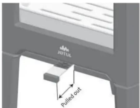
Fig. 25
- Open the ignition vent and air vent by pulling the handle all the way out. (Use a glove or something similar to protect your hand in case the handles are hot.)
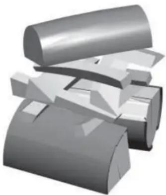
- Place two logs at the bottom of the burn chamber and pile the kindling in layers.
- Finally, place a medium-sized log on the top of the pile.
- Place 2 or 3 briquettes or kindling sticks under the top layer of kindling and light the fire.
ENGLISH
Heating
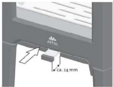
Fig. 26
- Leave the ignition-/air vent 24mm (Fig. 26) open when the wood has caught fire properly and is burning well.
- Close the door.
- You can then regulate the rate of combustion to give the heat you want by adjusting the air vent.
- Check that the afterburning (secondary combustion) starts. This is best indicated by yellow, flickering flames in front of the holes under the baffle.
Adding firewood
Stoke the stove frequently but only add small amounts of fuel at a time. If the stove is filled too full, the heat created may cause extreme stress in the chimney. Add fuel to the fire in moderation. Avoid smouldering fires as this produces the most pollution. The fire is best when it is burning well and the smoke from the chimney is almost invisible.
5.2 Danger of overheating
The fireplace must never be used in a manner that causes overheating
Overheating occurs when there is too much fuel and/or too much air so that too much heat develops. A sure sign of overheating is when parts of the fireplace glow red. If this happens, reduce the air vent opening immediately.
Seek professional advice if you suspect that the chimney is not drawing properly (too much/too little draught). For further information, see «4.0 Installation» (Chimney and flue pipe).
5.3 Ash removal
The product have an ash pan which makes it easy to remove the ash.
Use the fireplace set (Fig. 24).
Warning: The fireplace set can get hot.
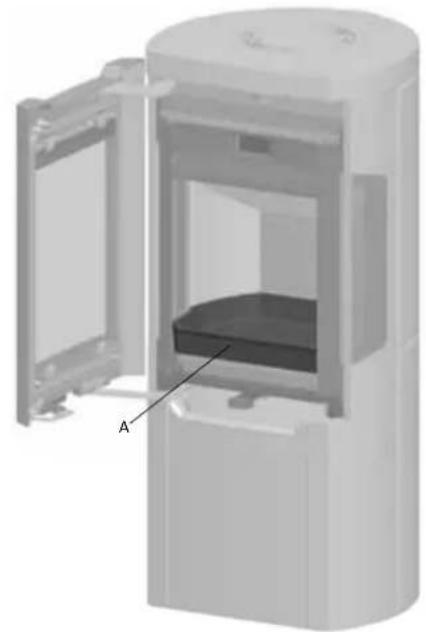
Fig. 27
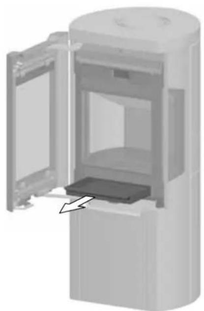
- Scrape the ash through the grate (Fig. 27A) in the base plate and into the ash pan. Use a glove to grab the handle on the ash pan.
- Make sure that the ash pan doesn't fill up so high that it keeps ash from coming through the grate into the pan.
6.o Service
Warning! Any unauthorised change to the product is not allowed. Only use original spare parts.
All service must be done when the stove is cold!
6.1 Changing the burn plates/inner bottom plate
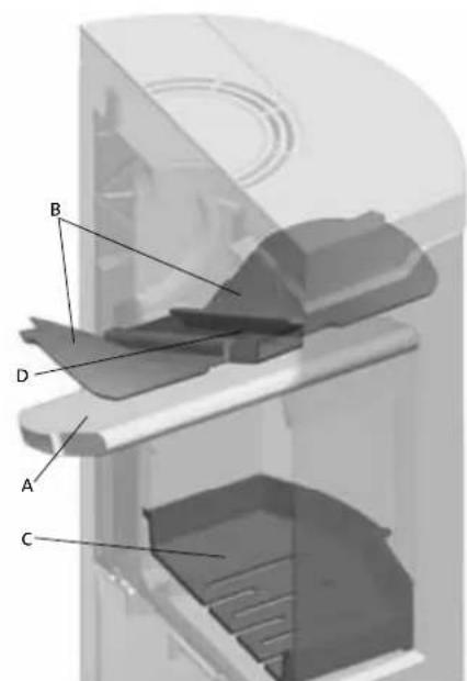
Fig.28
- Remove the baffle plate (Fig. 28 A)
- Remove the side burn plates (Fig. 28 E) by lifting them up a little and then out. (Be aware if using tools, that vermiculite plates may be damaged by rough handling).
- Unscrew the M8x25 mm screw on the rear burn plate (Fig. 28 F) and remove the burn plate.
- Then lift up and remove the inner bottom plate (Fig. 28C).
Follow the same procedure for installation, but in the opposite sequence.
6.2 Changing the baffle plate
- Lift the baffle plate (Fig. 28 A) and remove it through the door. Access is then easy to baffle plate II (Fig. 28 B) if this needs to be removed. This is situated on 1 knob on the side burn plate and on the air manifold (Fig. 28 D).
- Edge it down and remove it through the door. For re-installation follow the same procedure in the opposite sequence.
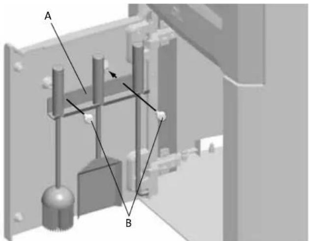
6.3 Adjusting the base door
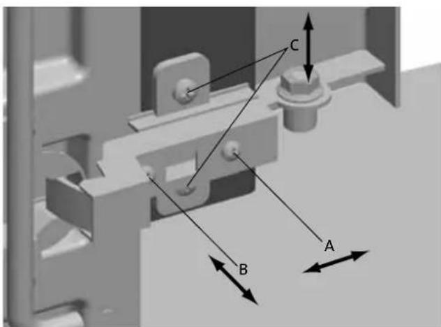
Fig. 29
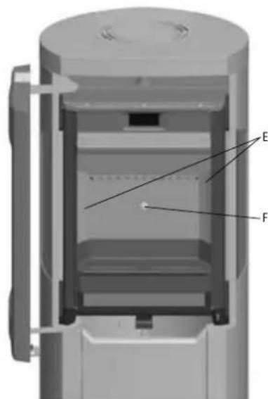
6.4 Changing the glass in the side panels
If needed the glass in the side panel can be replaced. Fig. 30
- Remove the base door by pressing against the rear of the hinge.
ENGLISH
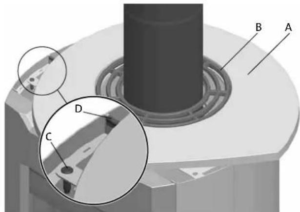
Fig. 31
If rear smoke outlet:
- Gently lift the top plate (Fig. 31 A), top grid (Fig. 31 B) and the bowl.
- Remove the pin (Fig. 31C) and the clip (Fig. 31D).
If top smoke outlet:
- Gently lift the top plate (Fig. 31A) and top grid (Fig. 31B).
- Turn the top plate and top grid approx. 60^ .
- Let the top plate and top grid rest on the stove.
- Remove the pin (Fig. 31C) and the clip (Fig. 31D).
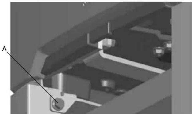
Fig. 32
- Remove the screw (fig. 32 A) on the inside of the base.
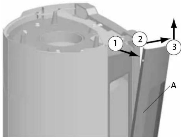
Fig. 33
- Pull the side panel out (fig. 33 A).
- Tilt the side panel gently to the front.
- Lift the side panel up.
- Replace glass and gasket.
For re-installation follow the same procedure in the opposite sequence.
6.5 Re-installation of the base door
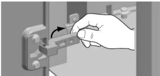
Fig. 34
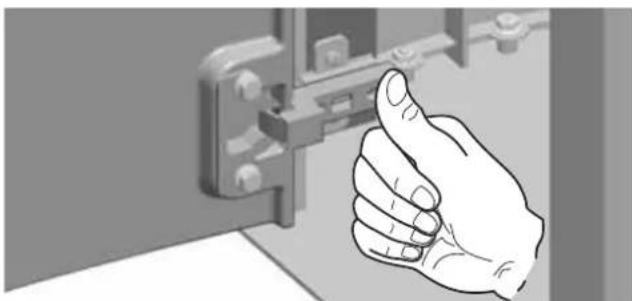
Fig. 35
If adjusting is needed - see figure 29.
7.o Maintenance
All maintenance must be done when the stove is cold!
7.1 Cleaning and soot removal
Soot deposits may build up on the internal surfaces of the fireplace during use. Soot is a good insulator and will therefore reduce the fireplace's heat output. If soot deposits accumulate when using the product, they can easily be removed by using a soot remover.
In order to prevent a water and tar layer from forming in the fireplace, you should regularly allow the fire to burn hot in order to remove the layer. An annual internal cleaning is necessary to get the best heating effect from your product. It is a good idea to do this when cleaning the chimney and flue pipes.
7.2 Sweeping flue pipes to the chimney
Flue pipes must be swept through the flue pipe sweeping hatch or through the door opening.
One of the baffles will have to be removed first in order to do this.
7.3 Inspection of the fireplace
Jotul recommends that you carefully inspect your fireplace yourself after it has been swept/cleaned. Check all visible surfaces for cracks. Also check that all joints are sealed and that the gaskets are in the correct position. Any gaskets showing signs of wear or deformation must be replaced.
Thoroughly clean the gasket grooves, apply ceramic glue (available from your local Jotul dealer) and press the gasket well into place. The joint will dry quickly.
7.4 Exterior maintenance
Painted products may change colour after several years' usage. The surface should be cleaned and brushed free of any loose particles before new paint is applied.
8.o Optional equipment
8.1 Soapstone top - 50 mm, complete
Cat.no.361080
8.2 Soapstone sides
Cat.no.351247
8.3 Soapstone set, complete
Cat.no.351248
Jøtul AS provides its customers with a ten-year warranty with the right to return external cast-iron items if they show defects as a result of faulty materials and/or manufacturing after the initial purchase/installation of the fireplace. The buyer is entitled to return the goods provided that the fireplace has been installed in compliance with current laws and regulations and in compliance with Jøtul's installation and operating instructions.
The warranty does not cover:
The installation of optional extras, for example, to rectify local draught conditions, air supply or other circumstances beyond Jotul's control. The warranty does not cover consumables, such as burn plates, smoke baffles, fire grates, bottom grates, brick refractories, dampers and gaskets as they deteriorate over time due to normal wear and tear. The warranty does not cover damage caused as a result of using unsuitable fuel when lighting the fire, such as driftwood, impregnated and painted wood, plank offcuts, chipboard, etc. Overheating may easily occur if unsuitable fuel is used, i.e. the fireplace becomes red hot, which causes the paint to discolour and the cast iron parts to crack.
The warranty is not valid for damage caused while the product is in transit from the distributor to the delivery address. The warranty is not valid either for damage caused by the use of non-original parts.
FRANCAIS
Table des matieres
- a工程技术 de un tubo flexible, a technique for the construction of a tubo in the form of a tube.
- a technique for the construction of a tubo in the form of a tube.
- a technique for the construction of a tubo in the form of a tube.
- a technique for the construction of a tubo in the form of a tube.
Distance to wall with insulated flue pipe: See fig. 1a.
The outside air connection may be fitted directly to the product through:
8.o Optional equipment
8.1 Spekstenen bovenkant - 50 mm, complete
Art.nr.361080
8.2 Spekstenen lijpanelen
Art.nr.351247
8.3 Spekstenen, complete
Art.nr.351248
Quality control of stoves and fireplaces
Checked
Utfort Kontrollpunkt
Controlled item
Jøtul pursues a policy of constant product development. Products supplied may therefore differ in specification, colour and type of accessories from those illustrated and described in the manual.
Jotul AS has a quality system that conforms to NS-EN ISO 9001 for product development, manufacturing, and distribution of stoves and fireplaces. This policy gives our customers quality and safety piece of mind as a result of Jotul's vast experience dating back to when the company first started in 1853.