
WS100 - Surveillance Camera i-onik - Free user manual and instructions
Find the device manual for free WS100 i-onik in PDF.
| Product type | Wireless security system (control panel, sensors, remote control) |
| Brand | i-onik |
| Model | WS100 |
| Main panel power supply | 9V AC mains adapter (included) |
| Panel backup power supply | 1 x 9V alkaline battery |
| Built-in siren | 120 dB, adjustable duration (1 to 6 minutes) |
| Display | Backlit LCD (colours: yellow, red, green) |
| Number of supported sensors | Unlimited (8 zones) |
| Included sensors | 2 door/window sensors, 1 PIR motion detector, 1 keychain remote control |
| Door/window sensor power supply | 2 x AAA 1.5V alkaline batteries |
| Motion detector power supply | 1 x 9V alkaline battery |
| Remote control power supply | 1 x 12V alkaline battery |
| Operating frequency | 868.35 MHz ±0.5 MHz |
| Wireless range (panel to sensors) | Up to 250 metres (open space) |
| Wireless range (remote control) | Up to 665 metres (open space) |
| PIR detection angle | < 110 degrees |
| PIR detection range | High: < 15 m, Medium: < 6 m, Low: < 4 m |
| Power saving timer (movement) | 3 minutes after each detection |
| Auto dialer (optional) | Included in the pack, mains power + 4 x AA backup batteries |
| Operating modes | STANDBY, ARM (full alarm), HOME (mixed), ALERT (chime) |
| Mounting | Wall panel with screws and anti-tamper magnet; sensors by adhesive or screws |
| Maintenance and cleaning | Soft damp cloth, dry immediately; do not use solvents |
| Batteries | Do not mix types or states; recycle at end of life |
| General information | Manual available in multiple languages; support by email |
Frequently Asked Questions - WS100 i-onik
User questions about WS100 i-onik
0 question about this device. Answer the ones you know or ask your own.
Ask a new question about this device
Download the instructions for your Surveillance Camera in PDF format for free! Find your manual WS100 - i-onik and take your electronic device back in hand. On this page are published all the documents necessary for the use of your device. WS100 by i-onik.
USER MANUAL WS100 i-onik
60,14/min. For calls from mobile phones, the price may vary.
For more details and questions on how to operate the alarm kits, please go to www.i-onik.de
ionik
nometec
Deutsch
1. Erste Schritte
Please check that all of the following items were Included in the package before installing the System:
A. Smart Panel
B. Key Fob Remote Control
C. 2x Door/Window Sensor
D. Motion Sensor (WS-100; 1x, WS-200; 2x)
E, AC Adapter for Smart Panel
E. Double-sided adhesive pads for door/ window sensors
G. Screws & wall plugs (3 sets)
H. Mounting bracket for motion sensor
Mounting Template
Quick Start Guide
(Only for WS-200: Auto Dialler, see Quick Start Guide WS-110)

2. Installing the Batteries and Powering Up the System
Door/Window Sensor
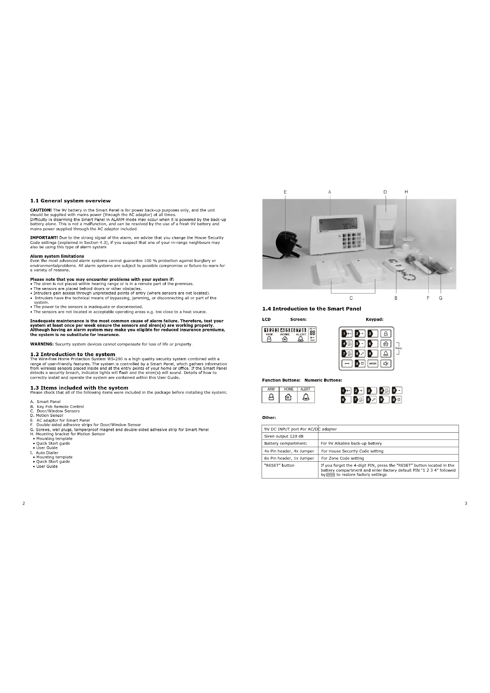
Requires 2x AAA batteries (not included). Slide off the battery cover, insert new batteries noting the polarity (Fig.1) and replace cover.
Motion Sensor
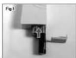
Requires 9 V battery (not included). Remove cover, insert a new 9 V battery noting the polarity (Fig. 2), then replace cover and screw.
Smart Panel
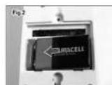
Requires 9 V battery (not included) & AC adaptor (included). The Smart Panel is supplied with a demonstration switch to show the LCD display panel working, whilst the unit is in its packaging. Before powering up the Smart Panel, the wire for this switch must be removed. To do this first unscrew the battery compartment and remove the cover. The demonstration switch wire is in the top right hand corner of the compartment (Fig. 3). Unplug the wire (Fig. 4) and discard it. Insert a new 9 V battery and plug in the AC adaptor to the Smart Panel (Fig. 5). Replace the battery compartment cover and screw. The adaptor can then be connected to a wall socket (Fig. 6).
3.Status Icon
3.1 ARM Mode
In ARM Mode, the Smart Panel's alarm will sound and the red LED will flash when the system is triggered.
3.2 ALERT Mode
In ALERT Mode, the Smart Panel's chime will sound and the green LED will flash when a visitor is detected.
3.3 HOME Mode
In HOME Mode, the system can operate in both the ARM and ALERT modes in different zones. The system comes with default settings that allow the system to operate directly after opening the package, but the settings can be adjusted to suit individual requirements.
4. Setting your PIN
To program your new 4-digit PIN
Make sure that you are in Standby Mode before taking any further steps.
To make sure you are in Standby Mode:
Enter default PIN of the press . The ' symbol onthe display will then disappear.
Step 1: Enter factory default PIN of 1 again then press, The symbol on the display
will then disappear
Step 2: Press to set new PIN.
Step 3: Enter your new 4-digit PIN then ENTE
Step 4: Re-enter your 4-digit PIN plus to confirm.
5. Enrolling the Remote Control
Note:
Before the key fob remote control supplied with the system is able to work it first needs to be enrolled (added onto the system) as follows:
Make sure that you are in Standby Mode before taking any further steps.
Step 1: Enter your 4-digit PIN (or default PIN of) then press . The ' symbol on the display will then disappear.
Step 2: Press then to enter Remote Control Enrol mode.
Step 3: Then press any key on the Remote Control to enrol it onto the system.
Step 4: Press to complete the enrolment.
6. Operating the ARM mode
Make sure that you are in Standby Mode before taking any further steps.
6.1 ARM the Alarm System
- Smart Panel
Enter your 4-digit PIN (or default PIN of 10) followed by then press to activate the ARM Mode.
- Remote Control
Press button on the remote control to activate the ARM mode.
The default exit delay is 15 seconds, with a visual countdown, before the system is armed.
6.2 Disarming the Alarm System
Enter your 4-digit PIN (or default PIN of 1234) followed by a disarm the system.
- Remote Control
Press button on the remote control to leave the mode.
The default entry delay time is 30 seconds, with a visual countdown, before the siren is activated.
7. Operating the ALERT Mode
Make sure that you are in Standby mode before taking any further steps.
7.1 Go into ALERT Mode
- Smart Panel
Enter your 4-digit PIN (or default PIN of 12) followed by the press to activate Alert Mode.
- Remote Control
Press button on the remote control to activate the mode.
7.2 Exit ALERT mode
Enter your 4-digit PIN (or default PIN of y@m#ed by
to exit Alert Mode.
- Remote Control
Press button on the remote control to leave the mode.
8. Muting the Audible Countdown
When the Smart Panel is armed the audible countdown (beeper) can be silenced by pressing the MUTE button, during the countdown. To reactivate the audible countdown (beeper) the MUTE button should be pressed again.
Deutsch
ionik hometec
WS-200 Wireless Alarmsystem
Handbuch

Chips and More GmbH
Gewerbestr.7 | 79112 Freiburg | Germany | www.i-onik.de
Service: +49 (0) 180-5000251*
Email: support@i-onik.de
€0,14/min. For calls from mobile phones, the price may vary.
ionik
homeotec
If you are interested in the following questions, please use our contact information:
1.1 General system overview
CAUTION! The 9V battery in the Smart Panel is for power back-up purposes only, and the unit should be supplied with mains power (through the AC adaptor) at all times. Difficulty in disarming the Smart Panel in ALARM mode may occur when it is powered by the back-up battery alone. This is not a malfunction, and can be resolved by the use of a fresh 9V battery and mains power supplied through the AC adaptor included.
IMPORTANT! Due to the strong signal of the alarm, we advise that you change the House Security Code settings (explained in Section 4.3), if you suspect that one of your in-range neighbours may also be using this type of alarm system
Alarm system limitations
Even the most advanced alarm systems cannot guarantee 100% protection against burglary or environmental problems. All alarm systems are subject to possible compromise or failure-to-warm for a variety of reasons.
Please note that you may encounter problems with your system if:
The siren is not placed within hearing range or is in a remote part of the premises.
The sensors are placed behind doors or other obstacles.
- Intruders gain access through unprotected points of entry (where sensors are not located).
- Intruders have the technical means of bypassing, jamming, or disconnecting all or part of the system.
The power to the sensors is inadequate or disconnected.
The sensors are not located in acceptable operating areas e.g. too close to a heat source.
Inadequate maintenance is the most common cause of alarm failure. Therefore, test your system at least once per week ensure the sensors and siren(s) are working properly. Although having an alarm system may make you eligible for reduced insurance premiums, the system is no substitute for insurance.
WARNING: Security system devices cannot compensate for loss of life or property.
1.2 Introduction to the system
The Wire-free Home Protection System WS-200 is a high quality security system combined with a range of user-friendly features. The system is controlled by a Smart Panel, which gathers information from wireless sensors placed inside and at the entry points of your home or office. If the Smart Panel detects a security breach, indicator lights will flash and the siren(s) will sound. Details of how to correctly install and operate the system are contained within this User Guide.
1.3 Items included with the system
Please check that all of the following items were included in the package before installing the system:
A. Smart Panel
B. Key Fob Remote Control
C. Door/Window Sensors
D. Motion Sensor
E. AC adaptor for Smart Panel
F. Double-sided adhesive strips for Door/Window Sensor
G. Screws, wall plugs, tamperproof magnet and double-sided adhesive strip for Smart Panel
H. Mounting bracket for Motion Sensor
- Mounting template
Quick Start guide
-User Guide
L Auto Dialler
- Mounting template
Quick Start guide
-User Guide


1.4 Introduction to the Smart Panel

Function Buttons: Numeric Buttons:
| ARM | HOME | ALERT |
Other:
| 9V DC INPUT port For AC/D | C adaptor |
| Siren output 120 dB | |
| Battery compartment: | For 9V Alkaline back-up battery |
| 4x Pin header, 4x Jumper | For House Security Code setting |
| 8x Pin header, 1x Jumper | For Zone Code setting |
| "RESET" button | If you forget the 4-digit PIN, press the "RESET" button located in the battery compartment and enter factory default PIN "1 2 3 4" followed by ENTER to restore factory settings |
1.5 Introduction to the Smart Panel sound alert and backlight
| Operating Mode | Situation Sound | alert and backlight indication | |
| 1 ARM Zone triggered under ARM status | Alarm duration: Adjustable between 1 - 6 minutes (siren). Default is 1 minute Smart Panel - flashes red every 1.5 seconds with triggered zone indicated (To stop - enter 4-digit PIN and press ENTER). | ||
| Alarm set under ARM status | No sirenSmart Panel - flashes RED every 5 seconds providing an intruder deterrent (different from when an intrusion occurs and the panel rapidly and continuously flashes red). | ||
| 2 HOME Zone triggered under ARM status | Alarm duration: Adjustable between 1 - 6 minutes (siren). Default is 1 minute. Smart Panel - flashes red every 1.5 seconds with triggered zone indicated (To stop - enter 4-digit PIN and press ENTER). | ||
| Zone triggered under ALERT status | Sound output: Chime (ding-dong)Smart Panel - flashes green every 1.5 seconds with triggered zone indicated (To stop panel flashes - press ENTER). | ||
| 3 ALERT Zone triggered under ALERT status | Sound output: Chime (ding-dong)Smart Panel - flashes green every 1.5 seconds with triggered zone indicated (To stop panel flashes press ENTER). | ||
| 4 | STANDBY | Silent | Smart Panel - yellow backlight remains ON for 10 seconds after entering Into STANDBY mode. |
2.1 Installing the Smart Panel
WARNING: The i.onik® Smart Panel has a built-in tamper-proof switch to prevent the system being disabled by an intruder. When fixing the Smart Panel to a wall, first ensure that it is in Standby mode to avoid the alarm sounding.
2.1.1 Locating the Smart Panel and tamperproof switch
Determine the location of the Smart Panel, which should be placed:
within a few feet of an electrical outlet
- where it is easily accessible
away from doors or windows that could be accessed by intruders
- way from extreme temperature sources (radiators, ovens, stoves etc.) and large metal objects that could interfere with the wireless performance
2.1.2 Wall mounting the Smart Panel and tamperproof switch
- First cut out the mounting template for the Smart Panel along with the area which is marked out for the position of the tamperproof magnet (see below).


- Tape the template onto the wall, in the position you wish to install the Smart Panel.
- Mark on the wall the points for drilling holes for the wall plugs and mounting screws, and the position for mounting the tamperproof magnet.
- Drill the holes, insert wall plugs and locate the mounting screws for the Smart Panel.
- Ensure the mounting surface for the tamperproof magnet is clean.
- Peel back one layer of the protective film on the double-sided adhesive strip and attach it to the magnet.
- Peel back the remaining layer of protective film and press the magnet firmly in the marked position against the mounting surface until firmly attached
- Mount the wSmart Panel onto the wall.
- Once the Smart Panel has been installed the system can be powered up. The tamperproof system is enabled once the Smart Panel is switched to HOME, ALERT or ARM mode.
2.2 Powering up the Smart Panel controller
Note: The Smart Panel is supplied with a demonstration switch to show the LCD display panel working whilst the unit is in its packaging. Before powering up the Smart Panel the wire for this switch must be removed as described below (See Figs 1 & 2):
- Unscrew the battery compartment and remove the cover.
- Remove and discard the LED demo socket, if fitted (Fig. 2).
- Insert a new back-up battery (noting the polarity) and plug the AC adaptor into the Smart Panel (Fig. 3).
- Replace the cover and screw, and connect the AC adaptor to a wall socket. (Fig. 4).
| Step Description Note | |
| 1 Insert 9V Alkaline backup battery One bee will sound and the backlight will blink within 1 second (Yellow→Red→Green→Yellow) The Smart Panel will display the below image: The Smart Panel will enter "STANDBY" mode after the automatic self-checking is complete. Then will appear on the LCD screen. Enter the default 4-digit PIN "1234" | |
| 2 Battery voltage low level Plug in AC adapter to the DC socket in the back of the Smart Panel | The main power supply (with AC adaptor) must be plugged in at all times, with the 9V battery functio- ning as back-up power supply only, when the mains power supply is interrupted |
2.3 Understanding the battery and AC adaptor icon
| Battery Icon shows power status below: Full - ☐ High - ☐ Middle - ☐ Low - ☐ | Battery Icon shows when the AC power supply is unplugged or interrupted. 9V battery functions as BACK-UP only and the ☐ symbol means LOW BATTERY. The LCD backlight flashes YELLOW for 30 seconds and ☐ will blink until the new battery is replaced or the mains power supply (with AC adaptor) is plugged in. |
| AC Adaptor Icon ☐ | When the AC adaptor to the Smart Panel is connected to a wall socket, the AC symbol will appear. The backlight will be 'ON' for 10 seconds while the AC adaptor connects to the power supply. |
3.1 Programming your new 4-digit PIN
The Wire-free I.onk® Smart Panel is supplied with a default PIN of "1234". This can be changed to your own personalised PIN, or your own personalised PIN can be changed, as follows:
| Keys Description Note | ||
| 1 (1234/4-digit PIN)+ ENTER | You must be in STANDBY mode before programming your new 4-digit PIN | To make sure you are in STANDBY mode:- Enter the default PIN "1 2 3 4"- Press ENTER- The Smart Panel will display the image below when you are in STANDBY mode:1 2 3 4 5 6 7 8 (One beep indicates that you entered a valid PIN, three beep indicate that an invalid operation was performed). |
| 2 (1234/4-digit PIN)+ ENTER | Enter the default PIN "1 2 3 4" OR your new 4-digit PIN for setting followed by ENTER | The Smart Panel will display the below image:1 2 3 4 5 6 7 8 |
| 3 + 1 | Press → followed by 1 | - Press → then "1" to set the new PIN- The Smart Panel will display the below image:1 2 3 4 5 6 7 8 |
| 4 New 4-digit PIN+ ENTER | Enter the new 4-digit PIN followed by ENTER | - LCD display → flashes with "1"- Enter the new 4-digit PIN- Press ENTER to confirm |
| 5 New 4-digit PIN+ ENTER | Re-enter new PIN for followed by ENTER for final confirmation | - LCD display → flashes with "2"- Re-enter the new 4-digit PIN- Press ENTER for final confirmation (One beep indicates that you entered a valid PIN, two beep indicate that an invalid operation was performed). |
3.2 Transmitting an emergency (Panic) alarm
3.2.1 Using the Panic alarm
Pressing & buttons together on the Keypad or Key Fob Remote Control will immediately transmit an alarm signal to the Smart Panel, activating the siren, and transmitting an alarm signal to any optional response devices (Auto Dialer & Outdoor Bell Box), to request emergency assistance.
To disarm the Panic alarm
On the Smart Panel: Enter your 4-digit PIN followed by ENTER to exit from the Panic alarm. On the Key Fob Remote Control: Press to exit from the Panic alarm.
3.2.2 Using the Panic alarm without activating the siren
If you are forced to disarm the system, enter the Duress Password to stop the siren from sounding. The Smart Panel will then silently transmit an alarm signal to the optional response devices (Auto Dialer & Outdoor Bell Box) to request emergency assistance.
Enter the default 4-digit PIN + 1 3 3 4 1 ENTER
Enter your personalised 4-digit PIN+ + ENTER
3.3 Operating different modes
The system has 4 operating modes (STANDBY, ARM, ALERT, and HOME) to suit individual requirements.
These modes can be set as follows:
3.3.1 STANDBY mode
If in STANDBY mode, the Smart Panel is prepared for mode selection.
| Keys Description Note | ||
| 1 (1234/4-digit PIN) + ENTER | You must be in STANDBY mode before turning to ARM mode | To make sure you are in STANDBY mode:- Enter the default PIN "1 2 3 4"- Press ENTER- The Smart Panel will display the image below when you are in STANDBY mode:1 2 3 4 5 6 7 8(One beep indicates that you entered a valid PIN, three beep indicate that an invalid operation was performed). |
3.3.2 ARM mode
When in ARM mode, the Smart Panel siren will sound and the Smart Panel flashes RED every
1.5 seconds when the system is triggered.
ARM mode default setting:
| Sensor Zone Status (MODE) | ||
| Door/Window Sensor 1 ARM | ||
| Door/Window Sensor 2 ARM | ||
| Motion Sensor 8 ARM |
A. Adjusting Exit Delay
The default setting of the Smart Panel allows the user 20 seconds to exit the property before the alarm is ARMED. However, this Exit Delay can be adjusted to between 10 and 60 seconds as follows:
| Keys Description Note | ||
| 1 (1234/4-digitPIN)+ ENTER | You must be in STANDBY mode before adjusting the Exit Delay. | To make sure you are in STANDBY mode:- Enter the default PIN " 1 2 3 4 " OR your new 4-digit PIN- Press Enter- The Smart Panel will display the image below when you are in STANDBY mode:1 2 3 4 5 6 7 8 | - One beep indicates that you entered a valid PIN, three beep indicate that an invalid operation was performed). |
| 2 (1234/4-digitPIN)+ ENTER | Enter the default PIN " 1 2 3 4" OR your new 4-digit PIN for setting followed by ENTER. | The Smart Panel will display the below image:1 2 3 4 5 6 7 8 | |
| 3 + ENTER | Press Then (many times as required) to set the new Exit Delay. | - When pressed the first time the Smart Panel flashes with the number of seconds currently set for the Exit Delay (The factory default setting is 20 seconds).- Each time is pressed the Exit Delay is increased by a further 10 seconds between the adjustable range of 10 to 60 seconds.- The Exit Delay time on the LCD display will flash until the setting is completed. |
| 4 ENTER | Press to complete the setting ENTER. | Confirm the setting and return the Smart Panel to STANDBY by pressing ENTER. |
B. Adjusting Entry Delay
The default setting of the Smart Panel allows the user 30 seconds to enter the property and DISARM the alarm before it is triggered. However, this Entry Delay can be adjusted to between 10 and 60 seconds as follows:
| Keys Description Note | |||
| 1 (1234/4-digitPIN)+ Enter | You must be in STANDBY mode before adjusting the Entry Delay | To make sure you are in STANDBY mode:- Enter the default PIN " 1 2 3 4 " OR your new 4-digit PIN- Press Enter- The Smart Panel will display the image below when you are in STANDBY mode:1 2 3 4 5 6 7 8 [ ](One beep indicates that you entered a valid PIN, three beep indicates that an invalid operation was performed). | |
| 2 (1234/4-digitPIN)+ ENTER | Enter the default PIN "1 2 3 4" OR your new 4-digitPIN for setting followedby ENTER. | The Smart Panel will display the below image:1 2 3 4 5 6 7 8 |
| 3+ENTER | Press Enter (many times as required)to set the new EntryDelay. | -When is pressed the first time the Smart Panel flashes with the number of seconds currently set forthe Entry Delay (The factory default setting is30 seconds).Each time the Entry Delay is increased by a further 10 seconds between the adjustable range of10 to 60 seconds.The Entry Delay time on the LCD display will flashuntil the setting is completed. |
| 4ENTER | Press Enter to complete thesetting . | Confirm the setting and return the Smart Panel toSTANDBY by pressing ENTER. |
C. Adjusting the Alarm Duration
The default setting of the Smart Panel gives an alarm duration of 1 minute after being triggered. However, this alarm duration can be increased up to 6 minutes:
| Keys Description Note | ||
| 1 (1234/4-digit PIN) + ENTER | You must be in STANDBY mode before adjusting the Alarm Duration. | To make sure you are in STANDBY mode:- Enter the default PIN " 1 2 3 4 " OR your new 4-digit PIN- Press Enter- The Smart Panel will display the image below when you are in STANDBY mode:1 2 3 4 5 6 7 8 - (One beep indicates that you entered a valid PIN, three beepaids indicate that an invalid operation was performed). |
| 2 (1234/4-digit PIN) + ENTER | Enter the default PIN "1 2 3 4" OR your new 4-digit PIN for setting followed by ENTER. | The Smart Panel will display the below image:1 2 3 4 5 6 7 8 |
| 3 + ENTER | Press Then (as many times as required) to set the new Alarm Duration. | - When is pressed the first time the Smart Panel flashes with the number of minutes currently set for the Alarm Duration (The factory default setting is 1 minute).- Each time is pressed the alarm duration is increased by a further minute up to a maximum of 6 minutes.- The Alarm Duration on the LCD display will flash until the setting is completed. |
| 4 | ENTER | Confirm the setting and return the Smart Panel to STANDBY by pressing ENTER. |
D. Muting the Audible Countdown
When the Smart Panel is ARMED the audible countdown (beeper) can be silenced by pressing the MUTE button, during the countdown. To reactivate the audible countdown (beeper) simply press the MUTE button again.
E. Arming the system
On the Key Fob Remote Control: Press to ARM the system.
On the Smart Panel: First make sure the Smart Panel is in STANDBY mode, and then ARM the system by taking the following steps:
| Keys Description Note | ||
| 1 (1234/4-digit PIN) + ENTER | You must be in STANDBY mode before turning to ARM mode. | To make sure you are in STANDBY mode:- Enter the default PIN " 1 2 3 4 " OR your new 4-digit PIN- Press Enter- The Smart Panel will display the image below when you are in STANDBY mode:12345678(One beep indicates that you entered a valid PIN, three beep indicate that an invalid operation was performed). |
| 2 (1234/4-digit PIN) + ENTER + 3 | Enter 4-digit PIN, press ENTER and 4r ARM mode. | Exit delay: up to 15 seconds- There is a 15 second exit delay time with a visual and audible (beeping) countdown before the system is armed.(Press MUTE to disable the beeping countdown, press MUTE again to resume the beeping)- If the Zone is enabled, a number will appear as displayed in the image below:1234567815ARM- The system will then enter ARM mode after 15 seconds. |
When in ARM mode, the Smart Panel flashes red every 5 seconds, acting as a deterrent to potential intruders. However, if an intruder is detected the panel continuously and rapidly flashes red. Once an intrusion has occurred (with the zone triggered under ARM status), the alarm siren will sound and the Smart Panel flashes red every 1.5 seconds with the triggered zone indicated. After the initial triggering, the alarm will immediately sound, without delay, if any other sensors are triggered.
F. Disarming the system
- On the Smart Panel: Enter your 4-digit PIN followed by to disarm the system.
- On the Key Fob Remote Control: Press to disarm the system.
G. Zone settings
Programming each zone in ARM mode:
| Keys Description Note | ||
| 1 (1234/4-digit PIN)+ ENTER | You must be in STANDBY mode before turning to ARM mode | To make sure you are in STANDBY mode:- Enter the default PIN " 1 2 3 4 " OR your new 4-digit PIN- Press Enter- The Smart Panel will display the image below when you are in STANDBY mode:1 2 3 4 5 6 7 8(One beep indicates that you entered a valid PIN, three beep indicate that an invalid operation was performed). |
| 2. | 1234/4-digit PIN) + ENTER | Enter 4-digit PIN for setting followed by ENTER. | The Smart Panel will display the below image:1 2 3 4 5 6 7 8 |
| 3 | + A | Press Enter (66 many times as required) to set the new Exit Delay. | - Toggle 1, 2, 3, 4, 5, 6, 7, 8 to turn each zone ON or OFF - If no number appears, the zone is turned OFF - The Smart Panel will display the below image:1 2 3 4 5 6 7 8 ARM |
| 4 | ENTIR | Press Enter to complete the setting. | Confirm the setting and return the Smart Panel to STANDBY by pressing ENTER |
H. Triggers in ARM mode
Example: Zone 1 trigger
| Step Description Note | |
| 1 Under the "ARM" Mode The Smart Panel will display the below image: | |
| 2 System trigger | One beep indicates that the system is triggered. |
| 3 Entry delay 30 seconds There are 30 seconds of entry delay time with a visual countdown for disarming.Once an intrusion has occurred (zone triggered under ARM status), the alarm siren will sound for 1 minute and the Smart Panel flashes red every 1.5 seconds with the triggerred zone indicated, until the system is disarmed.To disarm the system, enter the 4-Digit PIN or press on the remote control. | |
| 4 Return to ARM mode after the initial triggering | After the Initial triggering, the alarm will immediately sound, without delay, if any other sensors are triggered. |
3.3.3 ALERT mode
If in Alert mode, the Smart Panel chime will sound and the Smart Panel flashes green every
1.5 seconds with the triggered zone indicated, when the system detects a visitor in the protected
area.
ALERT mode default setting:
| Sensor Zone Status (MODE) | ||
| Door/Window Sensor 1 | ALERT | |
| Door/Window Sensor 2 | ALERT | |
| Motion Sensor | 8 | ALERT |
A. Entering ALERT mode
On the Key Fob Remote: Press to activate.
- On the Smart Panel: First make sure the Smart Panel is in STANDBY mode, and then enter into ALERT mode by taking the following steps:
| Keys Description Note | ||
| 1 (1234/4-digit PIN) + ENTER | You must be in STANDBY mode before turning to ALERT mode | To make sure you are in STANDBY mode:- Enter the default PIN " 1 2 3 4 " OR your new 4-digit PIN- Press Enter- The Smart Panel will display the image below when you are in STANDBY mode:1 2 3 4 5 6 7 8 [ ](One beep indicates that you entered a valid PIN, three beep indicates that an invalid operation was performed). |
| 2 (1234/4-digit PIN) + ENTER + [ ] | Enter 4-digit PIN, press ENTER and [ ]r ALERT mode | - The system will then enter ALERT mode- If the Zone is enabled, a number will appear as displayed in the image below:1 2 3 4 5 6 7 8 [ ]ALERT |
B. Exiting the ALERT mode
On the Smart Panel: Enter your 4-digit PIN followed by ENTER to exit ALERT mode.
- On the Key Fob Remote Control: Press to exit ALERT mode.
C. Zone settings
Programming each zone in ALERT mode:
| Keys Description Note | |||
| 1 (1234/4-digit PIN) + ENTER | You must be in STANDBY mode before turning to ALERT mode. | You must be in STANDBY mode To make sure you are in STANDBY mode:- Enter default PIN 1 2 3 4 OR your new 4-digit PIN- Press ENTER- The Smart Panel will display the below image:1 2 3 4 5 6 7 8 ↘(One beep indicates that you entered a valid PIN, three beep indicate that an invalid operation was performed). | |
| 2 4-digit PIN + ENTER | Enter 4-digit PIN for setting followed by ENTER. | The Smart Panel will display the below image:1 2 3 4 5 6 7 8 ↘(One beep indicates that you entered a valid PIN, three beep indicate that an invalid operation was performed). | |
| 3 + ENTER | Press ENTER then ↘ to set the ALERT Mode. | Toggle 1, 2, 3, 4, 5, 6, 7, 8 to turn each zone ON or OFF- If no number appears, the zone is turned OFFThe Smart Panel will display the below image:1 2 3 4 5 6 7 8 ↘ALERT ↘ | |
| 4 ENTER | Press ENTER to complete the setting. | Confirm the setting and return the Smart Panel to STANDBY by pressing ENTER | |
3.3.4 HOME mode
There are default settings that allow the system to operate after opening the package. These settings can be adjusted to suit your individual requirements The HOME mode allows the system operate in both the ARM and ALERT modes in different zones.
HOME mode default setting:
| Sensor Zone Status (MODE) | ||
| Door/Window Sensor 1 ALERT | ||
| Door/Window Sensor 2 ALERT | ||
| Motion Sensor 8 ARM |
A. Entering the HOME mode
On the Key Fob Remote Control: Press to activate.
- On the Smart Panel; First make sure the Smart Panel is in STANDBY mode, and then enter HOME
mode by taking the following steps:
| Keys Description Note | |||
| 1 (1234/4-digit PIN) + ENTER | You must be in STANDRY mode before turning to HOME mode. | To make sure you are in STANDRY mode:- Enter default PIN 1 2 3 4 OR your new 4-digit PIN- Press ENTER- The Smart Panel will display the below image:1 2 3 4 5 6 7 8 - (One beep indicates that you entered a valid PIN, three beep indicate that an invalid operation was performed). | |
| 2 4-digit PIN + ENTER + | Enter 4-digit PIN, press ENTER and for HOME mode. | - Then system will enter HOME mode- If the Zone is enabled, a number will appear as displayed in the image below:1 2 3 4 5 6 7 8 - HOME - | |
B. Exiting the HOME mode
On the Smart Panel: Enter your 4-digit PIN followed by ENTP to exit HOME mode.
- On the Key Fob Remote Control: Press to exit HOME mode.
Programming each zone in HOME mode:
C. Zone settings
| Keys Description Note | ||
| 1 (1234/4-digit PIN)+ ENTER | You must be in STANDBY mode before turning to HOME mode. | You must be in STANDBY Mode before any steps.To make sure you are in STANDBY mode:- Enter default PIN of 1 2 3 4 or your 4-digit PIN- Press ENTER-The LCD screen will display the below image:1 2 3 4 5 6 7 8 + - (One beep indicates that you entered a valid PIN threebeeps indicate that an invalid operation was performed). |
| 2 4 - digit PIN + ENTER | Enter 4-digit PIN for setting followed by ENTER. | The Smart Panel will display the below image: \( \left\lbrack \begin{matrix} 1 & 2 & 3 & 4 & 5 & 6 & 7 & 8 \\ & \end{matrix}\right\rbrack \) (One beep indicates that you entered a valid PIN, three beeps indicate that an invalid operation was performed). |
| 3 | + + | Press Enter to set the HOME mode. Toggle 1,2,3,4,5,6,7,8 to turn each zone in diffe- rent mode Indicates ALERT mode for a zone Indicates ARM mode for a zone Indicates the zone is turned OFF, number will not appear The Smart Panel will display the below image:  |
| 4 | ENTER | Press ENTER to complete the setting. Confirm the setting and return the Smart Panel to STANDBY by pressing ENTER |
4.1 Introduction to the Sensors
This package includes 3 wireless sensors which have a pre-programmed default setting that begins working immediately once the battery is activated (the Key Fob Remote Control needs to be enrolled onto the system before it can operate - see Section 4.2.3). It is advisable to install the main package first and then personalise the settings once the system is functioning properly. This section should help you to change the system settings in order to create a more personal home environment.
4.2 Installing the Sensors
First, determine the location of the sensors.
*Note: The sensors should be placed:
-
where they are not easily accessible.
-
In the most vulnerable rooms or near key entry points,
-
away from extreme temperature sources (radiators, ovens, stoves etc.) and large metal objects that could interfere with the wireless performance.
-
where better RF performance can be achieved (if necessary).
Once you have selected a location for the Sensors, the system can be powered up.
4.2.1 Installing the Door/Window Sensor
The Door/Window Sensor consists of two parts, a transmitter and a magnet. Once this sensor is installed, and the two parts are fastened onto the door or window, the sensor will trigger and transmit a message to the Smart Panel when the door or window is opened. One Door/Window Sensor is pre-programmed in Zone 1 and the other one is set in Zone 2; however, these settings can be adjusted according to your requirements. (See 3.3 & 4.4 Zone Settings)
A. Powering up the the Door/Window Sensor
- Remove the battery cover; insert new batteries noting the polarity as shown in the diagram below and replace the cover. (Requires 2x AAA batteries)
- Low battery indication: If the batteries need to be replaced, the red LED on the transmitter will flash slowly.
B. Installing the Door/Window Sensor
- Mount the transmitter on a fixed surface such as a door or a window frame.
- Mount the magnet on a movable surface such as a door or a window.
- Ensure the > / < marks on the sides of the transmitter and magnet match up as shown in the diagram.
The transmitter and the magnet must be no more than 5 mm apart

C. Mounting with the double-sided adhesive pad
- Ensure the mounting surface is clean
- Peel back one layer of the protective film and attach it to the transmitter.
- Peel back the remaining layer of protective film and press the transmitter firmly in place against the mounting surface until firmly attached.
Repeat to attach the magnet.
4.2.2 Installing the Motion Sensor
The Motion Sensor is designed to sense movement in a given area.
Note: It is best if pets are not allowed onto higher surfaces so that the sensors are not triggered unnecessarily (no more than 1 metre high).
A. Powering up the Motion Sensor
- Remove the battery cover, insert and connect a 9V battery as shown in diagram below and replace the cover. (Requires 1x 9V battery)
- Low battery indication: If the batteries need to be replaced, the red LED will flash (not including entry/exit delay flashing).
B. Installing the Motion Sensor
First, determine the location of the Motion Sensor.
Note: The Sensor should be placed:
- In the most vulnerable rooms or near key entry points.
- on a solid surface between 1.8m to 2.4mm (6ft to 8ft) from the floor.
away from extreme temperature sources (radiators, ovens, stoves etc.).
away from direct sunlight.
-indoors only and not behind partitions - where better RF performance can be achieved (if necessary).
C. Sensor sensitivity
IMPORTANT! The Motion Sensor is designed with a power saving program and will remain Inactive for 3 minutes after each detection. Please bear this in mind during system set up.
The sensitivity of the Motion sensor is adjustable and can be changed by setting the connector, found in the battery compartment, on either the 'High', 'Middle' or 'Low' position. When the sensitivity is set to "Low", more movement is required to trigger the sensor. It is recommended to set the sensitivity to "Low" and perform a "Walk Test" (Described in part D). If the walk test result is satisfactory, the sensitivity does not require further adjustment. If the walk test result shows the sensitivity is too low, then the sensitivity can be set to "Middle" or "High" as required. It is recommended that a walk test be conducted after each change in sensitivity setting.
D. Walk test
After mounting the sensor at the desired location, it is important to perform a walk test in order to determine if the sensor is detecting the correct area.
The distance at which the sensor can detect motion can be adjusted by altering the angle of the sensor. To reduce the detection range, simply move the sensor downward and move the sensor upward to maximize the range.
Note: Enter into ALERT mode before you perform the walk test, so that the alarm is not triggered.
You should walk in the area that you would like the sensor to monitor. If movement is detected the red light inside the unit will appear. If the red light does not appear, adjust the mounting angle accordingly. Perform the walk test again after 3 minutes. Repeat this procedure until motion is detected. Whilst carrying out the test, there should be no movement in the detection area during the 3 minute interval.


Tips: The sensor should not face towards direct sunlight, be placed near heat or cold producing devices (i.e.
air conditioning, radiators, fans, ovens, heaters etc.) that may cause false triggers. Also perform the walk test in areas which the sensor is not intended to cover, to ensure movement cannot be detected. E. Mounting using screws.
- Hold the enclosed mounting template against the wall at the selected location and mark the points for drilling.
- Drill the holes and insert wall plugs.
- Attach the bracket to the mounting surface with the screws provided.
- Attach the Motion Sensor to the mounting bracket.
4.2.3 Introduction of Key Fob Remote Control
A. Introduction
The i. onik Alarmsystem Remote Control allows you to operate the systems Smart Panel remotely, from inside or outside the property. Using the control the system can be armed or disarmed and the siren can be activated instantly if required (using the Panic function).
B. Operation
a. Powering up the Key Fob Remote Control
The Remote Control includes a 12V alkaline battery. To activate, unscrew and remove the back of the Remote Control, and carefully remove the clear plastic insulation tab from the battery. If the battery is dislodged, replace it noting the correct polarity as shown inside the battery compartment. Replace the battery cover.
b. Enrolling the Remote Control onto the Smart Panel
Note: Before being able to use the Key Fob Remote Control supplied with the system, or any additional Remote Controls, they first need to be enrolled (added onto the system) as follows:
| Keys Description Note | ||
| 1 (1234/4-digitPIN)+ ENTER | You must be in STANDBY mode before enrolling a new Remote Control onto the Smart Panel. | To make sure you are in STANDBY mode:- Enter the default PIN " 1 2 3 4 "OR your new 4-digit PIN- Press Enter- The Smart Panel will display the image below when you are in STANDBY mode:1 2 3 4 5 6 7 8(One beep indicates that you entered a valid PIN, three beep indicate that an invalid operation was performed). |
| 2 (1234/4-digitPIN)+ ENTER | Enter the default PIN " 1 2 3 4 " OR your new 4-digit PIN for setting followed by ENTER. | The Smart Panel will display the below image:1 2 3 4 5 6 7 8 |
| 3 + ENTER | Press then to enter the Remote Control Enrol mode. Then press any key on the new Remote Control to enrol it onto the system. | -LCD display flashes the ID no. of the remote to be enrolled e.g. when enrolling the first remote ID no."01" will flash. Once the first remote is enrolled the "02" will flash ready for a second remote to be enrolled (One beep indicates that the remote was enrolled to the Smart Panel successfully)Note: It is recommended that the ID No. is marked on the remote in case it needs to be deleted at a later stage |
| 4 ENTER | Press ENTER to complete the setting. | Confirm the setting and return the Smart Panel to STANDBY by pressing ENTER |
c. Operating the Key Fob Remote Control
The remote can be used to arm, disarm, and operate the system instantly.
ARM - Pressing the ARM button on the remote will arm the system, triggering the preset exit delay. When triggered the Smart Panel's LED light will flash Red and indicate the triggered zone.
DISARM - Pressing the DISARM button on the remote will disarm the system instantly and the system will return to Standby mode.
ALERT - Pressing the ALERT button on the remote will put the system into Alert mode and a chime will sound if any of the sensors are triggered. The Green light on the Smart Panel LED display will flash and indicate the triggered zone.
HOME - Pressing the HOME button on the remote will set the system in Home mode which will operate the system in both Arm and Alert modes in different preset zones.
PANIC - If the HOME and ALERT buttons are pressed together the systems alarm is Immediately activated.
d. Deleting a Remote Control from the Smart Panel
If a Remote Control device is damaged or lost, it can be deleted from the system as follows:
| Keys Description Note | ||
| 1 (1234/4-digitPIN)+ ENTER | You must be in STANDBY mode before deleting a Remote Control from the Smart Panel. | To make sure you are in STANDBY mode:- Enter the default PIN " 1 2 3 4 "OR your new 4-digit PIN- Press ENTER-The Smart Panel will display the image below when you are in STANDBY mode:1 2 3 4 5 6 7 8+ - The Smart Panel will display the image below when you are in STANDBY mode:(One beep indicates that you entered a valid PIN, three beep indicate that an invalid operation was performed). |
| 2 (1234/4-digitPIN)+ ENTER | Enter the default PIN " 1 2 3 4 " OR your new 4-digit PIN for setting followed by ENTER | The Smart Panel will display the below image:1 2 3 4 5 6 7 8+ |
| 3 + ENTER | Press → then to enter the Remote Control Deleting mode. Then Input the ID no. of the Remote Control you wish to delete from the system. | -LCD display flashes the total number of remote currentlyenrolled to the systemf(e.g. If the Smart Panel has 3 remotes enrolled the LCDdisplay will flash "03").- Input the remote ID no. (e.g. "02") for the remote you wish to delete (Inputting "00" will delete all remote controls).- LCD display will then flash the total number of remotes enrolled after deletion. (One beep indicates that the remote was successfully deleted from the Smart Panel). |
| 4 ENTER | Press ENTER to complete the deletion. | Confirm the deletion and return the Smart Panel to STANDBY by pressing ENTER. |
e. Querying the ID Number of a Remote Control
The ID number of a Remote Control device can be identified as follows:
| Keys Description Note | ||
| 1 (1234/4-digit PIN)+ ENTER | You must be in STANDBY mode before deleting a Remote Control from the Smart Panel. | To make sure you are in STANDBY mode:- Enter the default PIN " 1 2 3 4 "OR your new 4-digit PIN- Press ENTER-The Smart Panel will display the image below when you are in STANDBY mode:1 2 3 4 5 6 7 8 (+)One beep indicates that you entered a valid PIN,three beeps indicate that an invalid operation was performed). |
| 2 (1) 1234/4-digit PIN) + ENTER | Enter the default PIN " 1 2 3 4 " OR your new 4-digit PIN for setting followed by ENTER. | The Smart Panel will display the below image: 1 2 3 4 5 6 7 8 |
| 3 | + + | Press to go into Remote Querying mode, and then press any key on the remote to check its ID. |
| 4 | ENTER | Press ENTER to complete the query. Complete the query and return the Smart Panel to STANDBY by pressing ENTER |
4.3 House Security Code settings
In most cases the factory settings of the House Security Code will NOT need to be changed. However, if the Smart Panel and Sensors activate intermittently or do not work at all, this may be due to interference with other systems, which can be avoided by changing the House Security Code. To change this code, take the following steps with each system module:
1) There are 4 jumpers/Dip-switches on each device. To locate these remove the battery compartment cover.
2) Then set the Jumpers as shown below (ON-Push In / OFF-Pull out) to change the House Security Code setting. Make sure the Jumpers on the Smart Panel and its Sensors exactly match each other AND the Dip-switch setting on the Key Fob Remote Control.
| Jumper for House Security Code | HOUSE CODE 4321 | - Smart Panel - Each sensor Default House Security Code: 1: ON, 2: ON, 3: ON, 4: ON Jumper: ON = Pushed in, OFF = Pulled out |
| Dip-switches for House Security Code |  | - Key Fob Remote Control Default House Security: 1: ON, 2: ON, 3: ON, 4: ON |
4.4 Zone Code settings
Sensors are supplied with pre-assigned Zone settings to make setup easy - the Door/Window Sensors are pre-assigned to Zones 1 & 2 and the Motion Sensor to Zone 8.
To assign a Sensor to a different zone, the Zone Code on the Sensor needs to be changed. To change this code, take the following steps:
1) There is a Zone Code Jumper on each Sensor which can be located by removing the Jumper compartment cover.
2) Then pull out the Jumper and reassign it to the new Zone (Zones 1 to 8) as shown in the diagram below.
3) Replace and screw back the cover to complete the Zone Code setting.
| Jumper for Zone Code | ZONE CODE 87654321 | ZONE CODE 87654321 | ZONE CODE 87654321 | Default zone code: Door/Window sensor - Zone 1 Door/Window sensor - Zone 2 Motion sensor - Zone 8 |
5.1 Getting Started
5.1.1 Introduction to the Auto Dialler / Distress Alarm
The I. onike Auto Dialer / Distress Alarm is designed to silently send a pre-recorded message to up to 8 pre-programmed telephone numbers (first 2 are priority numbers) when triggered. The Auto Dialer's built-in microphone and speaker allow those people called to listen in on, and talk to, the household to gain a better understanding of the nature of the emergency.
The Auto Dialer / Distress Alarm can work either independently or in conjunction with the i-onik Alarmsystem, being activated when the system's Smart Panel is triggered by one of its sensors.
The Auto Dialler can be activated in three ways:
1) When the Ion Alarmsystem is triggered and sends out the alarm activation signal.
2) When Panic Buttons on the keypad of Auto Dialler and are pressed down simultaneously. 3) When the red "Emergency" button on the Panic Remote Control is pressed.
For installation and proper use of the Auto Dialer, please familiarise yourself with this User Guide. Instructions on programming the Auto Dialer are contained in the Quick Start Guide section.
5.1.2 Special Note
- This device must be connected directly to a public switched telephone network (PSTM), phone line (with an individual phone number) with tone frequency at 450Hz + / - 20Hz . A standard phone jack is provided for this connection.
- This equipment cannot be used on party lines, coin operated phone lines, ISDN connections or any part of a private or corporate switch board system.
5.1.3 Items included with the System
Please check that all of following items were included in the package before installing the Auto
Dialler/Distress Alarm:
1x 1onik* Auto Dialer / Distress Alarm
1x Telephone connector
1x AC adaptor
5.2 Installing the Auto Dialler
5.2.1 Location
Determine the location of the Auto Dialler, which should be placed:
- within a few feet of an electrical outlet and near a telephone or telephone jack (it is recommended that the Auto Dialler is also hidden out of sight for security purposes).
where it is NOT be easily accessible
away from doors or windows that could be accessed by intruders.
- away from extreme temperature sources (radiators, ovens, stoves etc) and large metal objects that could interfere with wireless performance
Once the location has been selected the Auto Dialler can be powered up
5.2.2 Powering up the WS-110 Auto Dialler
- Unscrew the battery compartment and remove the cover
- Insert new batteries, noting the polarity as shown in the battery compartment (Requires 4x AA alkaline batteries) and replace the cover
-
Plug in the AC adaptor to the Auto Dialler and connect it to a wall socket
LCD will blink within 1 second after being powered up. -
When the power supply switches from the battery to the AC Adaptor, the symbol will appear
Note: The 4x AA alkaline batteries serve as backup power only when AC power failed. You should not
rely on battery power and make sure the proper AC power is supplied to the Dialler at all times - Low battery indication: If the batteries need to be replaced, the 100 on flashes
5.2.3 Mounting the Auto Dialler / Distress Alarm
- Mount the transmitter on a fixed surface such as a wall, close to a telephone connection, using the screw and wall plug provided
5.2.4 Connecting Auto Dialler to your home telephone
A phone line must be connected to the Dialler in order for the Auto Dialler to work.
- Open the battery compartment to reveal 2 sockets for telephone cables
- Connect the "Line" socket to your well-telphone jack
- Connect the "Phone" socket to your telephone, which then will share the phone line with the Auto Dialer.
Normal telephone functions are interrupted only during an emergency, when the Auto Dialler takes control of the phone line.
5.2.5 Troubleshooting
If the LCD screen shows "FAIL" this means that the telephone line is not properly attached or phone
connections are invalid. Please check the connection.
If the recording quality is low, Please record again in a quiet environment with your mouth close to the microphone. (2-6 inches).
5.3 Quick Start Guide
| Step 1: Enter SETUP mode for prior to any program- ming | To ENTER SETUP mode | Press \( \oplus \oplus \) to activate the keyboard Enter the 4-DIGIT PIN (Default PIN is '1234'). Press \( \oplus \oplus \) to go into SETUP mode. | |
| To RECORD a message | Press and hold \( \oplus \oplus \) key for 2 seconds until REC shows on the screen to start the recording. Speak clearly into the microphone to record the mes- sage Recording will finish when you press \( \oplus \oplus \) again or after 20 seconds of recording. | ||
| Example message: This is a security alert from [your name] at [your address]. After listening to this message, please press the hash key (#) and press '1' to listen in to this address or '3' to speak. | |||
| Step 2: Under SETUP mode | To PLAYBACK your message | Press and release \( \oplus \oplus \) to playback the recorded message. | |
| To CHECK PHONE NUMBERS | Press \( \oplus \oplus \) (Display will show '1' for the first number). Press \( \oplus \oplus \) again for checking subsequent phone numbers. | ||
| To ENTER/ STORE PHONE NUMBERS | Press \( \oplus \oplus \) (Display will show '1' for the first number) Repeat this step to choose which phone number you wish to program (1-8). Press \( \oplus \oplus \) and enter the phone number digits (maxi- mum 15 digits). If number entered incorrectly, press \( \oplus \oplus \) to clear the number and re-enter the phone number digits Press \( \oplus \oplus \) to finish. | ||
| To ERASE a stored phone number | Press \( \oplus \oplus \) (Display will show '1' for the first number). Repeat this step to choose which phone number you wish to erase (1-8). Press \( \oplus \oplus \) then \( \oplus \oplus \) confirm erasing. |
| To program the number of DIALLING CYCLES | Press Display will show '1' for the first number) Repeat this step until the display shows . Press then enter the number of cycles you wish the Auto Dialler to run through (select 1 to 9 cycles, default cyle is 3 times) and press to confirm. | |
| To CHANGE the 4-DIGIT PIN | Press Display will show '1' for the first number) Repeat this step until the display shows \( \blacktriangleright \) Press and enter a new 4-DIGIT PIN. Re-enter the new 4-DIGIT PIN and press to confirm. | |
| To ENTER ALERT MODE | Press to enter ALERT mode. | |
| Step 3: Under ALERT mode | To activate EMERGENCY DIALLING | When triggered by an external sensor, the I.onik? Auto Dialler immediately starts dialling through the stored telephone numbers according to the number of dialling cycles you have programmed. |
| To activate PANIC DIALLING | Press and simultaneously or press the PANIC button on the KEYFOB remote. | |
| To CANCE EMERGENCY or PANIC DIALLING | If the EMERGENCY or PANIC DIALLING has been activated in error, the dialling can only be cancelled by disconnecting the mains power to the Auto Dialler and disconnecting the battery backup. |
5.4. Instructions for the Recipient
Note: There are several things that your call recipients should know in order to successfully receive and terminate an emergency call from your Auto Dialer. Therefore make sure your Auto Dialer recipients understand what to do when they receive your emergency call by passing them a copy of these instructions.
5.4.1 To START speakerphone conversation
- After having full listened to the recorded message, press the hash key (#), to confirm that the message is NOT merely delivered to a voice mail.
- Activate the "Listening-in" function by pressing "1" and "Speaking-in" function by pressing "3". These can only be used when the call recipient presses the Hash key (#).
- Time out period is 60 seconds and recipients can extend either the listening time or speaking time by pressing "1" or "3" accordingly. With each pressing, a further 60 seconds will be allowed by the Auto Dialler.
The conversation will be disconnected if the Auto Dialler receives no instruction.
5.4.2 To STOP the emergency message of the existing call AND all the remaining calls.
The Auto-Dialler will continue dialling the numbers until the call is answered
- The recipient can stop the Auto Dialler by waiting until the message has finished, and pressing () .
- This will stop the Auto Dialler from calling this and all remaining phone numbers.
- As this termination stops the Auto Dialler from calling any more phone numbers, the recipient must know the exact situation before terminating it.
5.4.3 To DISCONNECT all calls after conversation
Once the speakerphone conversation is over, the recipient should disconnect the call by pressing (#) instead of just hanging up the phone. This will terminate the connection for all existing call and the remaining calls.
5.5 CANCELLING the Auto Dialler
- If the Auto Dialler is activated in error it can only be cancel by:
- The recipient following the instructions in 4.2
- Cutting off the mains power supply to the Auto Dialler AND disconnecting the back-up battery
5.6 House Security Code Settings
Unless the factory settings of the Wire-free Home Protection System Smart Panel have been altered, the House Security Code will NOT need to be changed.
However, if the settings on the Smart Panel have been altered, or need to be altered to solve the problem of the Smart Panel and sensors activating intermittently (or not working at all) or interference with other systems, then the House Security Code on all system modules (sensors and sirens), will also need to be changed.
House Security Code settings can be altered as follows:
There are 4 jumpers or dip-switches on each device.
- Remove the battery compartment cover then toggle the dip switch contacts to change the House Security Code
- If the dip switch is up it is ON if it is down it is OFF. Default code on the Auto Dialler is with all the dip switches ON (up)
- To ensure the system works correctly, make sure the jumpers on the Smart Panel and all other system modules (sensors and sirens) match exactly.
| Jumper for House Security Code | HOUSE CODE 4321 | - Smart Panel - Each sensor Default house code: 1: ON, 2: ON, 3: ON, 4: ON Jumper: ON = Plugged, OFF = Pull Out |
| Dip-switches for House Security Code | III | - Key Fab Remote Default house code: 1: ON, 2: ON, 3: ON, 4: ON |
5.7 Maintenance
The product may be cleaned with a soft damp cloth and then wiped dry. Do not use abrasive, solvent based or aerosol cleaners as this may damage and/or discolour the product. Do not allow water to enter or attempt to clean inside the unit.
5.8 Batteries
Do not allow the batteries to corrode or leak as this may cause permanent damage to the product. Take care to insert the batteries with the correct polarity as shown inside the battery compartments. Do not mix new and old batteries or different types of batteries. Do not use rechargeable batteries. At the end of their useful life the batteries should be disposed of via a suitable recycling centre. Do not dispose of with your normal household waste. DO NOT BURN.
5.9 Alarm System Limitations
Even the most advanced alarm systems cannot guarantee 100% protection against burglary or environmental problems. All alarm systems are subject to possible compromise or failure-to-warm for a variety of reasons.
Please note that you may encounter problems with your system if:
The sensors are not placed within hearing range of persons sleeping or remote parts of the premises.
The sensors are placed behind doors or other obstacles.
Intruders gain access through unprotected points of entry (where sensors are not located).
- Intruders have the technical means of bypassing, jamming, or disconnecting all or part of the system.
The power to the sensors is inadequate or disconnected.
- The sensors are not located in proper environmental/temperature conditions i.e. too close to a heat source.
Note: Inadequate maintenance is the most common cause of alarm failure; therefore, test your system at least once per week to be sure the sensors and sirens are working properly.
Although having an alarm system may make you eligible for reduced insurance premiums, the system is no substitute for insurance.
6.1 FAQs
- What is the best way to set up my system? Where should I put my Smart Panel and the sensors?
We recommend that you take some time in advance to think about the placement of the Smart Panel and Sensors. The best location for the Smart Panel is usually by the main entry/exit point, in a hallway, or in another central location in your home. However, it must be plugged into a power socket, which may dictate where it can be placed.
- Please note that the alarm is pre-programmed with default settings, allowing you a pre-determined amount of time to enter (30 seconds) and time to exit (20 seconds) before the alarm sounds. front door you can either change the default setting to allow more time to enter/exit your home or, alternatively use the Key Fob to disarm the system.
2. How many Sensors can the Smart Panel support?
An unlimited number of sensors can be supported by the system, added to different zones in your house, as you see fit.
3. What wireless range should I expect from Sensors?
The range will vary depending on the type of structure; however, in an open space, the sensors should be capable of transmitting a signal up to 150 metres from the Smart Panel. Determine the location of the sensors first and change to a different location for better RF performance.
4. How do I attach my Sensors?
Adhesive tape and screws are provided for the purpose of securely mounting these items. Please refer to the user guide for more information about mounting the Smart Panel and the wireless sensors.
5. Do I have to programme the Smart Panel?
The Wire-free Home Protection System WS-200 is designed for easy installation. This means that the wireless sensors are in a default setting already registered to the Smart Panel and will therefore function immediately after the sensors are powered up. If you choose to buy additional accessories, these will need to be added to your system using the easy to follow instructions. Note: Due to the strong signal of the alarm, we advise that you change the House Security Code settings following section 4.3 of this manual, if you suspect that one of your in-range neighbours may also be using this alarm system.
6. Can I still use the same system if I move?
The Wire-free Home Protection System WS-200 is completely portable. If you move, you can remove your Smart Panel and wireless accessories and re-install them in your new property.
7.What if I forget my PIN?
If you forget your PIN, you may press the "Reset" button inside the battery compartment of the Smart Panel and the PIN will be reset to the factory default PIN 1234.
8. Why does my Motion Sensor not respond to movement?
Motion Sensor are very sensitive so to preserve battery life the Sensor will go to "Sleep" after an event has been identified and reported to the panel. This "Sleep" period lasts 3 minutes, after which, if no activity is detected, the Motion Sensor will again become active and ready to detect other events.
9. Why does my Motion Sensor keep generating false alarms?
If you have a pet, make sure they have not triggered the system. Remember, sensitivity to pets increases in certain circumstances e.g. the nearer the pet to the Sensor.
6.2 Troubleshooting
AC power failure:
This may occur if your security system is accidentally unplugged or if there has been a main power cut. If a full power failure occurs, please contact your electric company to find out the source of the problem. The back-up battery will continue to run the system for approximately 6 hours. System battery failure:
This may occur if the emergency back-up battery has been drained and needs to be replaced. If AC power is not restored, the low battery symbol will flash indicating that the Smart Panel back-up battery is running low. The back-up battery should be replaced once the low battery symbol appears. Sensor failure:
This may occur if a sensor is not communicating with the Smart Panel. It is necessary for you to ensure the House Security Code dipswitch and jumpers of the sensors are set correctly to the Smart Panel.
7.1 Product Information
Wireless systems are reliable and tested to high standards; however, it is important to consider that there are some limitations due to their transmitting power and range:
-
Receivers may be blocked by radio signals occurring on or near operating frequencies, regardless of the code selected.
-
A receiver can only respond to one transmitted signal at a time.
- Wireless equipment should be tested regularly to determine whether there are sources of interference and to protect against faults.
7.2 Specifications
7.2.1 Smart Panel
Power source: AC adaptor
Back up power: 9V alkaline battery x1 pc
Sensor numbers: Unlimited
House Code: 4 Jumpers
Operating frequencies: 868.35 MHz +/-0.5 MHz
Siren output: 120 dB (Duration-adjustable)
7.2.2 Key Fob Remote Control
Power source: 12V alkaline battery x 1 pc
RF working transmission frequency: 868.35 MHz +/-0.5 MHz
House Code: 4 Jumpers
Wireless range to Smart Panel: <65 meters (open area)
7.2.3 Door/Window Sensor
Power source: AAA alkaline battery 1.5V x 2 pcs
RF working transmission frequency: 868.35 MHz +/-0.5 MHz
House Code: 4 Jumpers
Zone Code: Pin header: 8 pin
Wireless range to Smart Panel: <250 metres (open area)
7.2.4 Motion Sensor
Power source: 9V alkaline battery x1 pc
RF working transmission frequency: 868.35 MHz +/-0.5 MHz
PIR detection angle: <110 Degree (@9VDC)
PIR detection range: "H": < 15M "M": < 6M "L": < 4M
House Code: 4 Jumpers
Zone Code: Pin header: 8 pin
Wireless range to Smart Panel: <250 meters (open area)
Power saving timer: 3 minutes
7.2.5 Auto Dialler
Power source: AC Adaptor
Back up power: AA alkaline battery x 4 pcs
House Code: 4 Jumpers
Operating frequencies: 868.35MHz +/-0.5MHz
Italiano
ionik hometec
WS-200 Wireless Alarmsystem
Manuale

Fig.3 (WS-101) Fig.4 (WS-101)
Password Editors PIN 1
Digicare h code PIN a 4 clre of default +
5.2 Installer I'Auto Dialler
5.2.1 Emplacement


- Deutsch
- Erste Schritte
- Installing the Batteries and Powering Up the System
- Door/Window Sensor
- Motion Sensor
- Smart Panel
- 3.Status Icon
- ARM Mode
- ALERT Mode
- HOME Mode
- Setting your PIN
- Enrolling the Remote Control
- Note:
- Operating the ARM mode
- ARM the Alarm System
- - Smart Panel
- - Remote Control
- Disarming the Alarm System
- Operating the ALERT Mode
- Go into ALERT Mode
- Exit ALERT mode
- Muting the Audible Countdown
- ionik hometec
- Chips and More GmbH
- General system overview
- Alarm system limitations
- Please note that you may encounter problems with your system if:
- Introduction to the system
- Items included with the system
- Introduction to the Smart Panel sound alert and backlight
- Installing the Smart Panel
- Locating the Smart Panel and tamperproof switch
- Wall mounting the Smart Panel and tamperproof switch
- Powering up the Smart Panel controller
- Programming your new 4-digit PIN
- Transmitting an emergency (Panic) alarm
- Using the Panic alarm
- To disarm the Panic alarm
- Using the Panic alarm without activating the siren
- Operating different modes
- STANDBY mode
- ARM mode
- Adjusting Exit Delay
- Adjusting Entry Delay
- Adjusting the Alarm Duration
- Muting the Audible Countdown
- Arming the system
- Disarming the system
- Zone settings
- Triggers in ARM mode
- ALERT mode
- Entering ALERT mode
- Exiting the ALERT mode
- Zone settings
- HOME mode
- Entering the HOME mode
- Exiting the HOME mode
- Introduction to the Sensors
- Installing the Sensors
- Installing the Door/Window Sensor
- Powering up the the Door/Window Sensor
- Installing the Door/Window Sensor
- Mounting with the double-sided adhesive pad
- Installing the Motion Sensor
- Powering up the Motion Sensor
- Installing the Motion Sensor
- Note: The Sensor should be placed:
- Sensor sensitivity
- Walk test
- Introduction of Key Fob Remote Control
- Operation
- a. Powering up the Key Fob Remote Control
- b. Enrolling the Remote Control onto the Smart Panel
- c. Operating the Key Fob Remote Control
- d. Deleting a Remote Control from the Smart Panel
- e. Querying the ID Number of a Remote Control
- House Security Code settings
- Zone Code settings
- Getting Started
- Introduction to the Auto Dialler / Distress Alarm
- The Auto Dialler can be activated in three ways:
- Special Note
- Items included with the System
- Installing the Auto Dialler
- Location
- Powering up the WS-110 Auto Dialler
- Mounting the Auto Dialler / Distress Alarm
- Connecting Auto Dialler to your home telephone
- Troubleshooting
- Instructions for the Recipient
- To START speakerphone conversation
- To STOP the emergency message of the existing call AND all the remaining calls.
- To DISCONNECT all calls after conversation
- CANCELLING the Auto Dialler
- House Security Code Settings
- House Security Code settings can be altered as follows:
- Maintenance
- Batteries
- Alarm System Limitations
- Note: Inadequate maintenance is the most common cause of alarm failure; therefore, test your system at least once per week to be sure the sensors and sirens are working properly.
- Although having an alarm system may make you eligible for reduced insurance premiums, the system is no substitute for insurance.
- FAQs
- How many Sensors can the Smart Panel support?
- What wireless range should I expect from Sensors?
- How do I attach my Sensors?
- Do I have to programme the Smart Panel?
- Can I still use the same system if I move?
- 7.What if I forget my PIN?
- Why does my Motion Sensor not respond to movement?
- Why does my Motion Sensor keep generating false alarms?
- Troubleshooting
- AC power failure:
- Product Information
- Specifications
- Smart Panel
- Key Fob Remote Control
- Door/Window Sensor
- Motion Sensor
- Auto Dialler
- Installer I'Auto Dialler
- Emplacement
Brand : i-onik
Model : WS100
Category : Surveillance Camera