NX5900B - Talkie Walkie KENWOOD - Free user manual and instructions
Find the device manual for free NX5900B KENWOOD in PDF.
| Product Type | Professional Digital/Analog Transceiver (Walkie-Talkie) |
| Brand | Kenwood |
| Model | NX5900B |
| Power Supply | 13.6 V DC ±15% (12 V negative ground system) |
| Current Consumption | 2 A max (on SB output) |
| Battery Type | Vehicle battery (user-supplied) |
| Antenna | 50 Ω (RF and GPS) |
| Microphone | KMC-35 (supplied), 8-pin microphone jack |
| Internal Speaker | Yes, 3.5 mm external speaker jack (4 W/4 Ω) |
| Display | LCD with function, zone, channel, and time indicators |
| Channels and Zones | Programmable (names up to 14 and 16 characters) |
| Communication Modes | Analog, Digital (AMBE+2™), Mixed |
| Connectivity | Bluetooth®, GPS, serial port (RS-232C), USB |
| Storage | microSD / microSDHC memory card (Class 2+, no SDXC) |
| Main Functions | Scanning, VOX, Noise Reduction, Talk Around, Scrambler, Monitoring, Auto Recording |
| Safety | Power off in explosive atmosphere, complies with FCC/IC regulations |
| Maintenance | Clean with a soft, dry cloth; do not use solvents |
| Supplied Accessories | DC power cable (with 15 A fuses), mounting bracket, screws, KMC-35 microphone, hook, user guide |
| Repairability | Consult a qualified technician; spare parts available from Kenwood dealer |
Frequently Asked Questions - NX5900B KENWOOD
User questions about NX5900B KENWOOD
0 question about this device. Answer the ones you know or ask your own.
Ask a new question about this device
Download the instructions for your Talkie Walkie in PDF format for free! Find your manual NX5900B - KENWOOD and take your electronic device back in hand. On this page are published all the documents necessary for the use of your device. NX5900B by KENWOOD.
USER MANUAL NX5900B KENWOOD
This User Guide covers only the basic operations of your radio. Ask your dealer for information on any customized features they may have added to your radio. For using details instruction manual (User Manual), refer to the following URL.
http://manual2.jvckenwood.com/en_contentse/search/


- SD^TM and micro SD^TM are trademarks of SD-3C, LLC in the United States. and/or other countries.
- The Bluetooth word mark and logos are registered trademarks owned by Bluetooth SIG, Inc. and any use of such marks by JVC KENWOOD Corporation is under license. Other trademarks and trade names are those of their respective owners.
THANK YOU
We are grateful you have chosen KENWOOD for your Digital Transceiver applications.
CONTENTS
NOTICES TO THE USER 3
PRECAUTIONS 4
TERMINAL DESCRIPTIONS 5
UNPACKING AND CHECKING EQUIPMENT 6
SUPPLIED ACCESSORIES 6
PREPARATION 7
ORIENTATION 9
OPERATION PANEL (ATTACHED PANEL OR KCH-19) 9
DISPLAY 10
BASIC OPERATION 13
SWITCHING POWER ON/ OFF 13
ADJUSTING THE VOLUME 13
SELECTING A ZONE AND CHANNEL 13
TRANSMITTING 13
RECEIVING 13
INFORMATION ON SOFTWARE LICENSE 14
NOTICES TO THE USER
- Government law prohibits the operation of unlicensed radio transmitters within the territories under government control.
- Illegal operation is punishable by fine and/or imprisonment.
Refer service to qualified technicians only.
Safety: It is important that the operator is aware of, and understands, hazards common to the operation of any transceiver.

WARNING
- EXPLOSIVE ATMOSPHERES (GASES, DUST, FUMES, etc.)
Turn OFF your transceiver while taking on fuel or while parked in gasoline service stations. Do not carry spare fuel containers in the trunk of your vehicle if your transceiver is mounted in the trunk area.
- INJURY FROM RADIO FREQUENCY TRANSMISSIONS
Do not operate your transceiver when somebody is either standing near to or touching the antenna, to avoid the possibility of radio frequency burns or related physical injury.
DYNAMITE BLASTING CAPS
Operating the transceiver within 500 feet (150 m) of dynamite blasting caps may cause them to explode. Turn OFF your transceiver when in an area where blasting is in progress, or where "TURN OFF TWO-WAY RADIO" signs have been posted. If you are transporting blasting caps in your vehicle, make sure they are carried in a closed metal box with a padded interior. Do not transmit while the caps are being placed into or removed from the container.
One or more of the following statements may be applicable:
FCC WARNING
This equipment generates or uses radio frequency energy. Changes or modifications to this equipment may cause harmful interference unless the modifications are expressly approved by the party responsible/ JVC KENWOOD. The user could lose the authority to operate this equipment if an unauthorized change or modification is made.
INFORMATION TO THE DIGITAL DEVICE USER REQUIRED BY THE FCC
This equipment has been tested and found to comply with the limits for a Class B digital device, pursuant to Part 15 of the FCC Rules. These limits are designed to provide reasonable protection against harmful interference in a residential installation.
This equipment generates, uses and can generate radio frequency energy and, if not installed and used in accordance with the instructions, may cause harmful interference to radio communications. However, there is no guarantee that the interference will not occur in a particular installation. If this equipment does cause harmful interference to radio or television reception, which can be determined by turning the equipment off and on, the user is encouraged to try to correct the interference by one or more of the following measures:
- Reorient or relocate the receiving antenna.
- Increase the separation between the equipment and receiver.
- Connect the equipment to an outlet on a circuit different from that to which the receiver is connected.
- Consult the dealer for technical assistance.
This device complies with Industry Canada licence-exempt RSS standard(s). Operation is subject to the following two conditions: (1) this device may not cause interference, and (2) this device must accept any interference, including interference that may cause undesired operation of the device.
Under Industry Canada regulations, this radio transmitter may only operate using an antenna of a type and maximum (or lesser) gain approved for the transmitter by Industry Canada. To reduce potential radio interference to other users, the antenna type and its gain should be so chosen that the equivalent isotropically radiated power (e.i.r.p.) is not more than that necessary for successful communication.
The AMBE+2™ voice coding Technology embodied in this product is protected by intellectual property rights including patent rights, copyrights and trade secrets of Digital Voice Systems, Inc. This voice coding Technology is licensed solely for use within this Communications Equipment. The user of this Technology is explicitly prohibited from attempting to extract, remove, decompile, reverse engineer, or disassemble the Object Code, or in any other way convert the Object Code into a human-readable form. U.S. Patent Nos. #6,199,037, #6,912,495, #8,200,497, #7,970,606, and #8,359,197.
Firmware Copyrights
The title to and ownership of copyrights for firmware embedded in KENWOOD product memories are reserved for JVC KENWOOD Corporation.
PRECAUTIONS
Observe the following precautions to prevent fire, personal injury, and transceiver damage.
- Do not attempt to confi gure the transceiver while driving; it is too dangerous.
- Do not disassemble or modify the transceiver for any reason.
- Do not expose the transceiver to long periods of direct sunlight, nor place it near heating appliances.
- If an abnormal odor or smoke is detected coming from the transceiver, switch the transceiver power off immediately, and contact your KENWOOD dealer.
- Use of the transceiver while you are driving may be against traffic laws. Please check and observe the vehicle regulations in your area.
- Do not use options not specified by KENWOOD.
- Do not put the plastic bag used for packing of this equipment on the place which reaches a small child's hand. It will become a cause of suffocation if it wears fl atly.
- Do not place the transceiver on unstable surfaces.
- Keep the volume as low as possible to protect your hearing.
- Always switch the transceiver power off before installing optional accessories.
- To dispose of batteries, be sure to comply with the laws and regulations in your country or region.

CAUTION
- The transceiver operates in 12V negative ground systems only! Check the battery polarity and voltage of the vehicle before installing the transceiver.
- Use only the supplied DC power cable or a KENWOOD optional DC power cable.
- Do not cut and/or remove the fuse holder on the DC power cable.
- Do not place the microphone cable around your neck while near machinery that may catch the cable.

WARNING
For passenger safety, install the transceiver securely using the supplied or optional mounting bracket and screw set so the transceiver will not break loose in the event of a collision.
When using the Transceiver, refer to the "NOTICES TO THE USER" and "PRECAUTIONS". If the warnings are not observed, there may be the possibility to have any malfunction. In this case, press and hold the Power Switch for 5 seconds or more. If the malfunction persists, ask your dealer.
TERMINAL DESCRIPTIONS
ACC (D-SUB 25 Pin Connector)
| Pin No. Name I/O Description Specifi cation | |||
| 1 NC - Not used | |||
| 2 COM1 RXD I Serial Data Input | RS-232C compatible | ||
| 3 COM1_TXD O Serial Data Output | |||
| 4 AUX1/O9 I/O Programmable Function I/O 9 | Input Impedance 100 kΩOutput Impedance 100 Ω | ||
| 5 DI I Data Input | 0.5 V p-p (Typ.)Input Impedance 20 kΩ | ||
| 6 MI2 | I MIC Signal Input | 5 mVrms(Typ.)(STD Deviation)Input Impedance 600 Ω | |
| 7 GND | Ground | Ground | |
| 8 AUX1/O8 I/O Programmable Function I/O 8 | Input Impedance 100 kΩOutput Impedance 470 Ω | ||
| 9 COM2_TXD O Serial Data Output | TTL (0V - 5V) | ||
| 10 COM2 RXD I Serial Data Input | |||
| 11 GND | — Ground | Ground | |
| 12 AUX1/O7/BER_DATA | I/O | Programmable Function I/O 7 | Input Impedance 100 kΩOutput Impedance 100 Ω |
| 13 AUX1/O6/BER_CLK | I/O | Programmable Function I/O 6 | |
| 14 SB | O DC Power (Switched B) Output | 13.6 V ±15%2 A (Max) | |
| 15 AUXO2 | O | Programmable Function O 2 | Open DrainR (dc): 60 mΩ (Max)Idc (Max)= -500 mA |
| 16 AUXO1 | O | Programmable Function O 1 | |
| 17 AFO | O AF | Signal Output | 0.7 V p-p (Typ.)Output Impedance 100 Ω |
| 18 GND | — Ground | Ground | |
| 19 DEO | O RX Detected Signal Output | 0.28 Vp-p (Typ.)Output Impedance 100 Ω | |
| 20 AUX1/O5 I/O Programmable Function I/O 5 | Input Impedance 100 kΩOutput Impedance 470 Ω | ||
| 21 AUX1/O4 I/O Programmable Function I/O 4 | |||
| 22 AUX1/O3 I/O Programmable Function I/O 3 | |||
| 23 AUX1/O2 I/O Programmable Function I/O 2 | |||
| 24 AUX1/O1 I/O Programmable Function I/O 1 | |||
| 25 ME | — Mic Ground | Ground | |
Speaker Jack (3.5 mm Phone Jack) 4 W/4 Ω
| Pin No. | Name I/O Description | Specifi cation | |||
| 1 | SPO | O | External | Speaker Output | 4 Ω (Min) |
| 3 | GND | — | Ground | — | Ground |
DC Input Connector
| Pin No. Name I/O Description Specifi cation | |||
| Red B | I DC Power Input | 13.6 V ±15% | |
| Black GND | — Ground | Ground | |
Ignition Sense Input Terminal
| Pin No. | Name I/O Description | Specifi cation | ||
| Yellow | B | I | Ignition Sense Input | 13.6 V ±15% |
Microphone Jack
| Pin No. | Name I/O Description Specifi cation | |||
| 1 | BLC | O | Mic Backlight Control | Output Impedance 1 kΩ |
| D+ | I/O | USB Serial Data I/O | USB 2.0 | |
| 2 | SB | O DC | Power (Switched B) Output | 13.6 V ±15%200 mA (Max) |
| 3 | GND | — | Ground | Ground |
| 4 | PTT I PTT | Input Impedance 47 kΩ | ||
| TXD | O PC | Serial Data from Radio UART TTL (0V to 5V) | ||
| 5 | ME — Mic Ground | Ground | ||
| 6 | MIC | I | Mic Signal Input | Input Impedance 600 Ω |
| VBUS | I | USB VBUS | 5 V/ 1 mA (Typ.) | |
| 7 | HOOK | I | Hook | Input Impedance 1 kΩ |
| RXD | I | PC Serial Data to Radio | UART TTL (0V to 5V) | |
| D- | I/O | USB Serial Data I/O | USB 2.0 | |
| 8 | DM | I/O | Mic Data Detection | High Impedance |
RF Antenna Terminal
50Ω impedance
GPS Antenna Terminal
50Ω impedance
UNPACKING AND CHECKING EQUIPMENT
Note:
- The following instructions are for use by your KENWOOD dealer, an authorized KENWOOD service facility, or the factory.
Carefully unpack the transceiver. We recommend that you identify the items listed below before discarding the packing material. If any items are missing or have been damaged during shipment, fi le a claim with the carrier immediately.
SUPPLIED ACCESSORIES
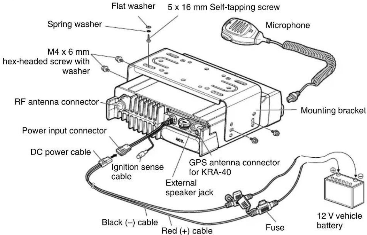
DC power cable (with fuses)
15 A fuse. 2
Mounting bracket
Screw set
- 5 × 16 ~mm self-tapping screw. 4
M4 x 6 mm hex-headed screw with washer 4
Spring washer. 4 - Flat washer 4
Microphone (with cable)
KMC-35. 1
- Microphone hanger (with 4 × 16 ~mm self-tapping screws)
User guide. 1
PREPARATION

WARNING
Various electronic equipment in your vehicle may malfunction if they are not properly protected from the radio frequency energy which is present while transmitting. Typical examples include electronic fuel injection, anti-skid braking, and cruise control. If your vehicle contains such equipment, consult the dealer for the make of vehicle and enlist his/her aid in determining if they will perform normally while transmitting.
Connecting the power cable

CAUTION
The transceiver operates in 12V negative ground systems only! Check the battery polarity and voltage of the vehicle before installing the transceiver.
1 Check for an existing hole, conveniently located in the fi rewall, where the power cable can be passed through.
- If no hole exists, use a circle cutter to drill a hole, then install a rubber grommet.
2 Run the power cable through the firewall and into the engine compartment.
3 Connect the red lead to the positive (+) battery terminal and the black lead to the negative (-) battery terminal.
- Place the fuse as close to the battery as possible.
4 Coil the surplus cable and secure it with a retaining band.
- Be sure to leave enough slack in the cables so the transceiver can be removed for servicing while keeping the power applied.
■ Installing the Transceiver

WARNING
For passenger safety, install the transceiver securely using the supplied or optional mounting bracket and screw set, so the transceiver will not break loose in the event of a collision.
Note:
- Before installing the transceiver, check how far the mounting screws will extend below the surface. When drilling mounting holes, be careful not to damage vehicle wiring or parts.
1 Mark the position of the holes in the dash, using the mounting bracket as a template. Using a 4.2mm (5/32 inch) drill bit, drill the holes, then attach the mounting bracket using the supplied screws.
- Mount the transceiver within easy reach of the user and where there is sufficient space at the rear of the transceiver for cable connections.
2 Connect the antenna and the supplied power cable to the transceiver.
3 Slide the transceiver into the mounting bracket and secure it using the supplied hex-headed screws.
4 Mount the microphone hanger in a location where it will be within easy reach of the user.
- The microphone and microphone cable should be mounted in a place where they will not interfere with the safe operation of the vehicle.

CAUTION
When replacing the fuse in the DC power cable, be sure to replace it with a fuse of the same value. Never replace a fuse with one that is rated with a higher value.
Using the microSD memory card
To install a microSD memory card on this transceiver, please consult your dealer.
- microSD memory cards (Class 2 or higher) and microSDHC memory cards (Class 2 or higher) can be used.
- SDXC memory cards cannot be used.
- This transceiver is not guaranteed to operate with all microSD memory cards. (Operations are confirmed on memory cards for the following brands: SanDisk, TOSHIBA and Panasonic.)
Compensation Disclaimer
Data stored on the microSD memory card may be altered or lost due to problems with this transceiver. We do not accept liability in respect of the data stored on your microSD memory card, failure to save the data properly, loss of data, and any direct or indirect damages.
ORIENTATION
OPERATION PANEL (ATTACHED PANEL OR KCH-19)
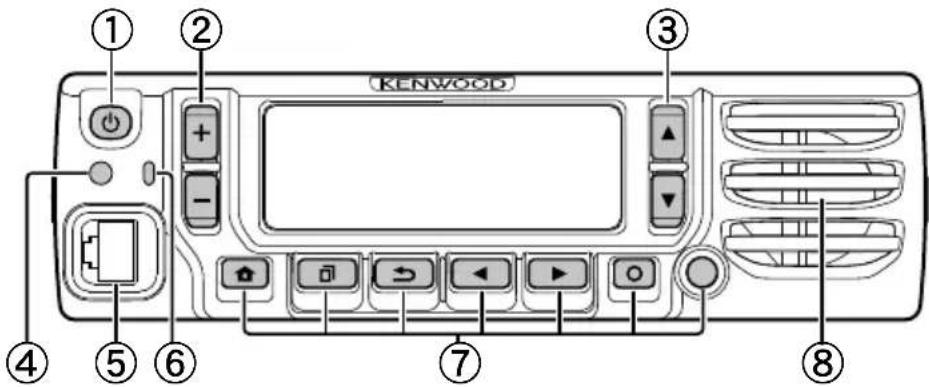
① [(Power) switch
Press to switch the transceiver ON or OFF.
② [+] / [−] keys
Press to activate its programmable function. The default key setting is [Volume Up]/[Volume Down].
3[ ] / [ ] keys
Press to activate its programmable function. The default key setting is [Channel Up]/[Channel Down].
④ Illumination sensor
Sensor for Auto Dimmer Function.
⑤ Microphone jack
Insert the microphone plug into this jack.
⑥ TX/RX Indicator
The indicator lights in different colors to indicate the current status of the transceiver.
Lights red while transmitting and green while receiving.
7[ ] / [ ] / [1] / [1] / [1] / [1] auxiliary (orange) keys
Press to activate their programmable functions.
[ ] : The default key setting is [Clear].
[] a: The default key setting is [Menu].
[ ] The default key setting is [Squelch Off Momentary].
[ ]: The default key setting is [Zone Down].
[ ]▶: The default key setting is [Zone Up].
[] o: The default key setting is [Function].
Auxiliary (orange): The default key setting is [None].
⑧ Speaker
Internal speaker.
For details on programming functions to the keys on your transceiver, please contact your dealer or refer to the "User Manual" available from the following URL.
http://manual2.jvckenwood.com/en_contentse/search/

DISPLAY Basic Frame
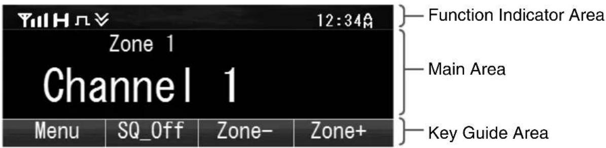
| Display Area Description | |
| Function Indicator Area | Displays the various function indicators, signal strength indicator and clock. |
| Main Area | Display the information of the transceiver such as Channel number and Zone number. |
| Key Guide Area | Display the key functions for [0], [1], [2] and [3] keys. |
Function Indicator
| Indicator Description | |
| YII | Displays the signal strength. |
| H | The channel is using high transmit power. |
| M | The channel is using medium transmit power. |
| L | The channel is using low transmit power. |
| Π | In Digital mode (Digital Channel) |
| ι | In Analog mode (Analog Channel) |
| Ω | In Digital mode (Mixed Channel) |
| Δ | In Analog mode (Mixed Channel) |
| § | The Bluetooth function is activated. Blinks in the process of turning on Bluetooth. |
| ® | Connected to Bluetooth device. |
| × | The GPS position is determined. Blinks when the GPS is unable to determine the position. |
| Non-priority Scan or Voting/Site Roaming is in progress. Blinks when the scan is paused. (green icon) | |
| Priority Scan is in progress. Blinks when the scan is paused. (red icon) | |
| F1 | Indicates Priority channel 1 or Priority Monitor ID 1. |
| F2 | Indicates Priority channel 2 or Priority Monitor ID 2. |
| F3 | Indicates Priority Monitor ID 3. |
| F4 | Indicates Priority Monitor ID 4. |
| The current channel is added to the scanning sequence. | |
| The current Zone is added to the Multi-Zone scanning sequence. | |
| The Scrambler function is activated. | |
| The Encryption function is activated. Blinks when receiving an encrypted carrier. | |
| AES | The Encryption (AES) function is activated. Blinks when receiving an encrypted carrier. |
| DES | The Encryption (DES) function is activated. Blinks when receiving an encrypted carrier. |
| The Talk Around function is activated. | |
| The Monitor or Squelch Off is activated. | |
| The External Speaker is activated. | |
| The External Speaker (Internal + External) is activated. | |
| NR | The Noise Reduction function is activated. Blinks when Noise Reduction is functioning. |
| Blinks when an incoming call matches your Optional Signaling. | |
| A message is stored in the memory. Blinks when a new message is received. | |
| SD | The microSD memory card is recognized. |
| The microSD memory card is not recognized. | |
| The VOX function is activated. | |
| F | The Site Lock function is activated. |
| G | The Broadcast Call function is activated. |
| O | The Surveillance function is activated. |
| V | The selected group is programmed as telephone IDs. Blinks during Auto Telephone search. |
| T | The Tactical Zone is activated. |
| M | The Horn Alert function is activated. |
| ◎ | The Public Address function is activated. |
| Z | The Intercom function is activated. |
| R | AUX A is activated. |
| B | AUX B is activated. |
| C | AUX C is activated. |
| △ | The Lone Worker function is activated. |
| †† | The Compander function is activated. |
| ○ | The Operator Selectable Tone function is activated. |
| 回 | Blinks during Auto Recording. |
| P | The Key Lock function is activated. |
SWITCHING POWER ON/ OFF
Press to switch the transceiver ON.
Press [O] again to switch the transceiver OFF.
ADJUSTING THE VOLUME
Press the key programmed as [Volume Up] to increase the volume. Press the key programmed as [Volume Down] to decrease the volume.
SELECTING A ZONE AND CHANNEL
Select the desired zone and channel using the keys programmed as [Zone Up]/[Zone Down] and [Channel Up]/[Channel Down].
- The transceivers may have names programmed for zones and channels. The zone name and channel name can contain up to 16 and 14 characters respectively. While selecting a zone, the zone name will appear above the channel name.
- If programmed by your dealer, your transceiver will announce the zone and channel numbers as you change them.
TRANSMITTING
1 Select the desired zone and channel.
2 Press the PTT switch and speak into the microphone. Release the PTT switch to receive.
- The LED indicator lights red while transmitting and green while receiving a signal. This indicator can also be disabled by your dealer.
- For best sound quality at the receiving station, hold the microphone approximately 1.5 inches (3 cm to 4 cm) from your mouth.
RECEIVING
Select the desired zone and channel. If signaling has been programmed on the selected channel, you will hear a call only if the received signal matches your transceiver settings.
INFORMATION ON SOFTWARE LICENSE
This unit uses a software based on the license below.
\*zlib LICENSE
Copyright (C) 1995-2013 Jean-Ioup Gailly and Mark Adler
This software is provided 'as-is', without any express or implied warranty. In no event will the authors be held liable for any damages arising from the use of this software.
Permission is granted to anyone to use this software for any purpose, including commercial applications, and to alter it and redistribute it freely, subject to the following restrictions:
- The origin of this software must not be misrepresented; you must not claim that you wrote the original software. If you use this software in a product, an acknowledgment in the product documentation would be appreciated but is not required.
- Altered source versions must be plainly marked as such, and must not be misrepresented as being the original software.
- This notice may not be removed or altered from any source distribution.
Jean-Ioup Gailly (jloup@gzip.org)
Mark Adler (madler@alumni.caltech.edu)
*Libpng LICENSE
This copy of the libpng notices is provided for your convenience. In case of any discrepancy between this copy and the notices in the file png.h that is included in the libpng distribution, the latter shall prevail.
COPYRIGHT NOTICE, DISCLAIMER, and LICENSE:
If you modify libpng you may insert additional notices immediately following this sentence.
This code is released under the libpng license.
libpng versions 1.2.6, August 15, 2004, through 1.6.8, December 19, 2013, are Copyright (c) 2004, 2006-2013 Glenn Randers-Pehrson, and are distributed according to the same disclaimer and license as libpng-1.2.5
with the following individual added to the list of Contributing Authors
Cosmin Truta
libpng versions 1.0.7, July 1, 2000, through 1.2.5 - October 3, 2002, are Copyright (c) 2000-2002 Glenn Randers-Pehrson, and are distributed according to the same disclaimer and license as libpng-1.0.6 with the following individuals added to the list of Contributing Authors
Simon-Pierre Cadieux
Eric S. Raymond
Gilles Vollant
and with the following additions to the disclaimer:
There is no warranty against interference with your enjoyment of the library or against infringement.
There is no warranty that our efforts or the library will fulfill any of your particular purposes or needs. This library is provided with all faults, and the entire risk of satisfactory quality, performance, accuracy, and effort is with the user.
libpng versions 0.97, January 1998, through 1.0.6, March 20, 2000, are Copyright (c) 1998, 1999 Glenn
Randers-Pehrson, and are distributed according to the same disclaimer and license as libpng-0.96, with the following individuals added to the list of Contributing Authors:
Tom Lane
Glenn Randers-Pehrson
Willem van Schaik
libpng versions 0.89, June 1996, through 0.96, May 1997, are Copyright (c) 1996, 1997 Andreas Dilger Distributed according to the same disclaimer and license as libpng-0.88, with the following individuals added to the list of Contributing Authors:
John Bowler
Kevin Bracey
Sam Bushell
Magnus Holmgren
Greg Roelofs
Tom Tanner
libpng versions 0.5, May 1995, through 0.88, January 1996, are Copyright (c) 1995, 1996 Guy Eric Schalnat, Group 42, Inc.
For the purposes of this copyright and license, "Contributing Authors" is defined as the following set of individuals:
Andreas Dilger
Dave Martindale
Guy Eric Schalnat
Paul Schmidt
Tim Wegner
The PNG Reference Library is supplied "AS IS". The Contributing Authors and Group 42, Inc. disclaim all warranties, expressed or implied, including, without limitation, the warranties of merchantability and of fitness for any purpose. The Contributing Authors and Group 42, Inc. assume no liability for direct, indirect, incidental, special, exemplary, or consequential damages, which may result from the use of the PNG
Reference Library, even if advised of the possibility of such damage.
Permission is hereby granted to use, copy, modify, and distribute this source code, or portions thereof, for any purpose, without fee, subject to the following restrictions:
- The origin of this source code must not be misrepresented.
- Altered versions must be plainly marked as such and must not be misrepresented as being the original source.
- This Copyright notice may not be removed or altered from any source or altered source distribution.
The Contributing Authors and Group 42, Inc. specifically permit, without fee, and encourage the use of this source code as a component to supporting the PNG file format in commercial products. If you use this source code in a product, acknowledgment is not required but would be appreciated.
A "png_get_copyright" function is available, for convenient use in "about" boxes and the like:
printf("%s",png_get)."copyright(NULL));
Also, the PNG logo (in PNG format, of course) is supplied in the files "pngbar.png" and "pngbar.jpg (88x31) and "pngnow.png" (98x31).
Libpng is OSI Certified Open Source Software. OSI Certified Open Source is a certification mark of the Open Source Initiative.
Glenn Randers-Pehrson
glennrp at users.sourceforge.net
December 19, 2013
*Md5
Copyright (C) 1999, 2000, 2002 Aladdin Enterprises. All rights reserved.
This software is provided 'as-is', without any express or implied warranty. In no event will the authors be held liable for any damages rising from the use of this software.
Permission is granted to anyone to use this software for any purpose, including commercial applications, and to alter it and redistribute it freely, subject to the following restrictions:
- The origin of this software must not be misrepresented; you must not claim that you wrote the original software. If you use this software in a product, an acknowledgment in the product documentation would be appreciated but is not required.
- Altered source versions must be plainly marked as such, and must not be misrepresented as being the original software.
- This notice may not be removed or altered from any source distribution.
L. Peter Deutsch
ghost@aladdin.com
ÉMETTEUR-RéCEPTEUR NUMÉRIQUE VHF
NX-5700 NX-5700(B)
ÉMETTEUR-RéCEPTEUR NUMÉRIQUE UHF
NX-5800 NX-5800(B)
ÉMETTEUR-RéCEPTEUR NUMÉRIQUE 700/800MHz
NX-5900 NX-5900(B)
GUIDE DE L'UTILISATEUR
MISE SOUS/ HORS TENSION 13
RÉGLAGE DU VOLUME 13
SELECTION D'UNE ZONE ET D'UN CANAL 13
TRANSMISSION 13
Réception 13
AVIS AUX UTILISATEURS
MISE SOUS/HORS TENSION
TRANSCCEPTOR DIGITAL VHF
NX-5700 NX-5700(B)
TRANSCEPTOR DIGITAL UHF
NX-5800 NX-5800(B)
TRANSCCEPTOR DIGITAL 700/800MHz
NX-5900 NX-5900(B)
GUIA DEL USUARIO
ACC (Conector D-SUB 25 pines)
| Número de Pin | Nombre E/S Descripción | Específ cación | |
| 1 NC — No uso | |||
| 2 COM1 RXD E Entrada de datos en series | Compatible con RS-232C | ||
| 3 COM1_TXD S Salida de datos en series | |||
| 4 AUXI/O9 E/S Entrada/ Salida deITCHUONpprogramable 9 | Impedancia de entrada 100 kΩImpedancia de salida 100 Ω | ||
| 5 DI E Entrada de datos | 0,5 V p-p (Tip.)Impedancia de entrada 20 kΩ | ||
| 6 MI2 E Entrada de senal MIC | 5 mVrms (Tip.) (Desviación ESTANDAR)Impedancia de entrada 600 Ω | ||
| 7 GND — Tierra | Tierra | ||
| 8 AUXI/O8 E/S Entrada/ Salida deITCHUONpprogramable 8 | Impedancia de entrada 100 kΩImpedancia deAPEXADAR | ||
| 9 COM2 TXD S Salida de datos en series | TTL (0 V a 5 V) | ||
| 10 COM2 RXD E Entrada de datos en series | |||
| 11 GND — Tierra | Tierra | ||
| 12 AUXI/O7/BER_DATA | E/S | Entrada/ Salida de funciona pprogramable 7 | Impedancia de entrada 100 kΩImpedancia deAPEXADAR |
| 13 AUXI/O6/BER_CLK | E/S | Entrada/ Salida de funciona pprogramable 6 | |
| 14 SB | S Salida de alimentación de CC (Conmutación B) | 13,6 V ±15%2 A (Max.) | |
| 15 AUXO2 | S | Salida de funciona programable 2 | Drenador AbiertoR (dc): 60 mΩ (Max.)Idc (Max.)= -500 mA |
| 16 AUXO1 | S Salida de funciona programable 1 | ||
| 17 AFO | S Salida de senal AF | 0,7 V p-p (Tip.)Impedancia deAPEXADAR | |
| 18 GND — Tierra | Tierra | ||
| 19 DEO | S Salida de senal detectada RX | 0,28 Vp-p (Tip.)Impedancia deAPEXADAR | |
| 20 AUXI/O5 E/S Entrada/ Salida deITCHUONpprogramable 5 | Impedancia de entrada 100 kΩImpedancia deAPEXADAR | ||
| 21 AUXI/O4 E/S Entrada/ Salida deITCHUONpprogramable 4 | |||
| 22 AUXI/O3 E/S Entrada/ Salida deITCHUONpprogramable 3 | |||
| 23 AUXI/O2 E/S Entrada/ Salida deITCHUONpprogramable 2 | |||
| 24 AUXI/O1 E/S Entrada/ Salida deITCHUONpprogramable 1 | |||
| 25 ME — Mic Tierra | Tierra | ||
© 2015 JVCKENWOOD Corporation