SR8400 - Receiver MARANTZ - Free user manual and instructions
Find the device manual for free SR8400 MARANTZ in PDF.
User questions about SR8400 MARANTZ
0 question about this device. Answer the ones you know or ask your own.
Ask a new question about this device
Download the instructions for your Receiver in PDF format for free! Find your manual SR8400 - MARANTZ and take your electronic device back in hand. On this page are published all the documents necessary for the use of your device. SR8400 by MARANTZ.
USER MANUAL SR8400 MARANTZ
AV Surround Receiver

CAUTION
RISK OF ELECTRIC SHOCK DO NOT OPEN

CAUTION: TO REDUCE THE RISK OF ELECTRIC SHOCK, DO NOT REMOVE COVER (OR BACK) NO USER-SERVICEABLE PARTS INSIDE
REFER SERVICING TO QUALIFIED SERVICE PERSONNEL

The lightning flash with arrowhead symbol within an equilateral triangle is intended to alert the user to the presence of uninsulated "dangerous voltage" within the product's enclosure that may be of sufficient magnitude to constitute a risk of electric shock to persons.

The exclamation point within an equilateral triangle is intended to alert the user to the presence of important operating and maintenance (servicing) instructions in the literature accompanying the product.
WARNING
TO REDUCE THE RISK OF FIRE OR ELECTRIC SHOCK,
DO NOT EXPOSE THIS PRODUCT TO RAIN OR MOISTURE.
CAUTION: TO PREVENT ELECTRIC SHOCK, MATCH WIDE BLADE OF PLUG TO WIDE SLOT, FULLY INSERT.
ATTENTION: POUR EVITER LES CHOC ÉLECTRIQUES, INTRODUIRE LA LAME LA PLUS LARGE DE LA FICHE DANS LA BORNE CORRESPONDANTE DE LA PRISE ET POUSSER JUSQU'AU FOND.
NOTE TO CATV SYSTEM INSTALLER:
This reminder is provided to call the CATV (Cable-TV) system installer's attention to Section 820-40 of the NEC which provides guidelines for proper grounding and, in particular, specifies that the cable ground shall be connected to the grounding system of the building, as close to the point of cable entry as practical.
NOTE:
This equipment has been tested and found to comply with the limits for a Class B digital device, pursuant to Part 15 of the FCC Rules. These limits are designed to provide reasonable protection against harmful interference in a residential installation. This equipment generates, uses and can radiate radio frequency energy and, if not installed and used in accordance with the instructions, may cause harmful interference to radio communications. However, there is no guarantee that interference will not occur in a particular installation. If this equipment does cause harmful interference to radio or television reception, which can be determined by tuning the
equipment off and on, the user is encouraged to try to correct the interference by one or more of the following measures:
- Reorient or relocate the receiving antenna.
- Increase the separation between the equipment and receiver.
- Connect the equipment into an outlet on a circuit different from that to which the receiver is connected.
- Consult the dealer or an experienced radio/TV technician for help.
IMPORTANT SAFETY INSTRUCTIONS
READ BEFORE OPERATING EQUIPMENT
This product was designed and manufactured to meet strict quality and safety standards. There are, however, some installation and operation precautions which you should be particularly aware of.
- Read Instructions - All the safety and operating instructions should be read before the product is operated.
- Retain Instructions - The safety and operating instructions should be retained for future reference.
- Heed Warnings - All warnings on the product and in the operating Instructions should be adhered to.
- Follow Instructions - All operating and use instructions should be followed.
- Cleaning - Unplug this product from the wall outlet before cleaning. Do not use liquid cleaners or aerosol cleaners. Use a damp cloth for cleaning.
- Attachments - Do not use attachments not recommended by the product manufacturer as they may cause hazards.
- Water and Moisture - Do not use this product near water-for example, near a bath tub, wash bowl, kitchen sink, or laundry tub, in a wet basement, or near a swimming pool, and the like.
-
Accessories - Do not place this product on an unstable cart, stand, tripod, bracket, or table. The product may fall, causing serious injury to a child or adult, and serious damage to the product. Use only with a cart, stand, tripod, bracket, or table recommended by the manufacturer, or sold with the product. Any mounting of the product should follow the manufacturer's instructions, and should use a mounting accessory recommended by the manufacturer.
-
A product and cart combination should be moved with care. Quick stops, excessive force, and uneven surfaces may cause the product and cart combination to overturn.

- Ventilation - Slots and openings in the cabinet are provided for ventilation and to ensure reliable operation of the product and to protect it from overheating, and these openings must not be blocked or covered. The openings should never be blocked by placing the product on a bed, sofa, rug, or other similar surface. This product should not be placed in a built-in installation such as a bookcase or rack unless proper ventilation is provided or the manufacturer's instructions have been adhered to.
-
Power Sources - This product should be operated only from the type of power source indicated on the marking label. If you are not sure of the type of power supply to your home, consult your product dealer or local power company. For products intended to operate from battery power, or other sources, refer to the operating instructions.
-
Grounding or Polarization - This product may be equipped with a polarized alternating-current line plug (a plug having one blade wider than the other). This plug will fit into the power outlet only one way. This is a safety feature. If you are unable to insert the plug fully into the outlet, try reversing the plug. If the plug should still fail to fit, contact your electrician to replace your obsolete outlet. Do not defeat the safety purpose of the polarized plug.
AC POLARIZED PLUG
- Power-Cord Protection - Power-supply cords should be routed so that they are not likely to be walked on or pinched by items placed upon or against them, paying particular attention to cords at plugs, convenience receptacles, and the point where they exit from the product.
- Protective Attachment Plug - The product is equipped with an attachment plug having overload protection. This is a safety feature. See Instruction Manual for replacement or resetting of protective device. If replacement of the plug is required, be sure the service technician has used a replacement plug specified by the manufacturer that has the same overload protection as the original plug.
-
Outdoor Antenna Grounding - If an outside antenna or cable system is connected to the product, be sure the antenna or cable system is grounded so as to provide some protection against voltage surges and built-up static charges. Article 810 of the National Electrical Code, ANSI/NFPA 70, provides information with regard to proper grounding of the mast and supporting structure, grounding of the lead-in wire to an antenna discharge unit, size of grounding conductors, location of antenna-discharge unit, connection to grounding electrodes, and requirements for the grounding electrode. See Figure 1.
-
Lightning - For added protection for this product during a lightning storm, or when it is left unattended and unused for long periods of time, unplug it from the wall outlet and disconnect the antenna or cable system. This will prevent damage to the product due to lightning and power-line surges.
- Power Lines - An outside antenna system should not be located in the vicinity of overhead power lines or other electric light or power circuits, or where it can fall into such power lines or circuits. When installing an outside antenna system, extreme care should be taken to keep from touching such power lines or circuits as contact with them might be fatal.
- Overloading - Do not overload wall outlets, extension cords, or Integral convenience receptacles as this can result in a risk of fire or electric shock.
- Object and Liquid Entry - Never push objects of any kind into this product through openings as they may touch dangerous voltage points or short-out parts that could result in a fire or electric shock. Never spill liquid of any kind on the product.
- Servicing - Do not attempt to service this product yourself as opening or removing covers may expose you to dangerous voltage or other hazards. Refer all servicing to qualified service personnel.
- Damage Requiring Service - Unplug this product from the wall outlet and refer servicing to qualified service personnel under the following conditions:
a. When the power-supply cord or plug is damaged.
b. If liquid has been spilled, or objects have fallen into the product.
c. If the product has been exposed to rain or water.
d. If the product does not operate normally by following the operating instructions. Adjust only those controls that are covered by the operating instructions as an improper adjustment of other controls may result in damage and will often require extensive work by a qualified technician to restore the product to its normal operation.
e. If the product has been dropped or damaged in any way, and
f. When the product exhibits a distinct change in performance - this indicates a need for service.
- Replacement Parts - When replacement parts are required, be sure the service technician has used replacement parts specified by the manufacturer or have the same characteristics as the original part. Unauthorized substitutions may result in fire, electric shock, or other hazards.
- Safety Check - Upon completion of any service or repairs to this product, ask the service technician to perform safety checks to determine that the product is in proper operating condition.
- Wall or Ceiling Mounting - The product should be mounted to a wall or ceiling only as recommended by the manufacturer.
- Heat - The product should be situated away from heat sources such as radiators, heat registers, stoves, or other products (including amplifiers) that produce heat.
FIGURE 1 EXAMPLE OF ANTENNA GROUNDING AS PER NATIONAL ELECTRICAL CODE,ANSI/NFPA 70
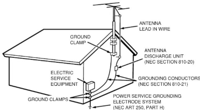
NEC-NATIONAL ELECTRICAL CODE
TABLE OF CONTENTS
INTRODUCTION 2
PRECAUTIONS 2
DESCRIPTION. 2
FEATURES 3
ACCESSIONS 3
FRONT PANEL 4
FL DISPLAY 5
REAR PANEL 6
REMOTE CONTROLLER RC1400 ....... 7
NAMES AND FUNCTIONS 7
LCD INDICATORS 8
REMOTE CONTROL RANGE 9
BATING BATTERIES 9
BATTENMENTREPEGMENTINTERVAL 10
GENERAL INFORMATION OF RC1400 TO SR3400-10
CONNECTIONS 11
SPEAKER PLACEMENT 11
CONNECTING SPEAKERS 11
CONNECTING AUDIO COMPONENTS 12
CONNECTINGVIDEOCOMPONENTS 13
ADVANCED CONNECTING 14
CONNECTING THE REMOTE CONTROL JACKS .... 14
CONNECTING THE ANTENNA TERMINALS 15
CONNECTING FOR THE MULTITROOM 18
SETUP 17
1 INPUT SETUP (ASSIGNABLE DIGITAL INPUT)
AND COMPONENTVIDEOINPUT)
2 SPEAKER SETUP 18
3 PREFERENCE 19
4 SUHROUND 20
5 PLTTI (PRO LOGIC II) MUSIC PARAMETER 20
6 CS II (CIRCLE SURROUND II) PARAMETER 20
7 MULTI ROOM 20
87.1 CH INPUT LEVEL 21
9 DC TRIGGER SETUP 21
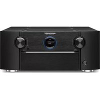
Thank you for purchasing the Marantz SR8400 Surround receiver.
This remarkable component has been engineered to provide you with many years of home theater enjoyment. Please take a few minutes to read this manual thoroughly before you connect and operate the SR8400.
As there are a number of connection and configuration options, you are encouraged to discuss your own particular home theater setup with your Marantz A/V specialist dealer.
PRECAUTIONS
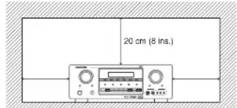
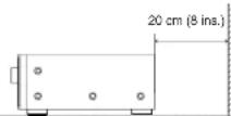
CAUTIONS ON INSTALLATION
For heat dispersal, leave at least 20~cm / 8 inch of space between the top, back and sides of this unit and the wall or other components.
Do not obstruct the ventilation holes.
DESCRIPTION

DTS was introduced in 1994 to provide 5.1 channels of discrete digital audio into home theater systems.
DTS brings you premium quality discrete multichannel digital sound to both movies and music.
DTS is a multichannel sound system designed to create full range digital sound reproduction.
The no compromise DTS digital process sets the standard of quality for cinema sound by delivering an exact copy of the studio master recordings to neighborhood and home theaters.
Now, every moviegoer can hear the sound exactly as the moviemaker intended.
DTS can be enjoyed in the home for either movies or music on of DVD's, LD's, and CD's.
"DTS" and "DTS Digital Surround" are registered trademarks of Digital Theater Systems, Inc.

The advantages of discrete multichannel systems over matrix are well known.
But even in homes equipped for discrete multichannel, there remains a need for high-quality matrix decoding. This is because of the large library of matrix surround motion pictures available on disc and on VHS tape; and analog television broadcasts.
The typical matrix decoder of today derives a center channel and a mono surround channel from two-channel matrix stereo material. It is better than a simple matrix in that it includes steering logic to improve separation, but because of its mono, band-limited surround it can be disappointing to users accustomed to discrete multichannel.
Neo:6 offers several important improvements as follow.
- Neo:6 provides up to six full-band channels of matrix decoding from stereo matrix material. Users with 6.1 and 5.1 systems will derive six and five separate channels, respectively, corresponding to the standard home-theater speaker layouts.
-
Neo:6 technology allows various sound elements within a channel or channels to be steered separately, and in a way which follows naturally from the original presentation.
-
Neo:6 offers a music mode to expand stereo nonmatrix recordings into the five- or six-channel layout, in a way which does not diminish the subtlety and integrity of the original stereo recording.

DTS-ES Extended Surround is a new multichannel digital signal format developed by Digital Theater Systems Inc. While offering high compatibility with the conventional DTS Digital Surround format, DTS-ES Extended Surround greatly improves the 360-degree surround impression and space expression thanks to further expanded surround signals. This format has been used professionally in movie theaters since 1999.
In addition to the 5.1 surround channels (FL, FR, C, SL, SR and LFE), DTS-ES Extended Surround also offers the SB (Surround Back) channel for surround playback with a total of 6.1 channels. DTS-ES Extended Surround includes two signal formats with different surround signal recording methods, as DTS-ES Discrete 6.1 and DTS-ES Matrix 6.1.
"DTS," "DTS-ES Extended Surround" and "Neo:6" are trademarks of Digital Theater Systems, Inc.

The stereo CD is a 16 bit medium with sampling at 44.1kHz . Professional audio has been 20- or 24-bit for some time, and there is increasing interest in higher sampling rates both for recording and for delivery into the home. Greater bit depths provide extended dynamic range. Higher sampling rates allow wider frequency response and the use of anti-alias and reconstruction filters with more favorable aural characteristics.
DTS 96/24 allows for 5.1channel sound tracks to be encoded at a rate of 96kHz / 24 bits on DVD-Video titles.
When DVD-video appeared, it became possible to deliver 24-bit, 96 kHz audio into the home, but only in two channels, and with serious limitations on picture. This capability has had little use.
DVD-audio allows 96/24 in six channels, but a new player is needed, and only analog outputs are provided, necessitating the use of the D/A converters and analog electronics provided in the player.
DTS 96/24 offers the following:
- Sound quality transparent to the original 96/24 master.
- Full backward compatibility with all existing decoders. (Existing decoders will output a 48 kHz signal)
- No new player required: DTS 96/24 can be carried on DVD-video, or in the video zone of DVD-audio, accessible to all DVD players.
4.96/24 5.1-channel sound with full-quality full-motion video, for music programs and motion picture soundtracks on DVD-video.

Dolby Digital identifies the use of Dolby Digital audio coding for such consumer formats as DVD and DTV. As with film sound, Dolby Digital can provide up to five full-range channels for left, center, and right screen channels, independent left and right surround channels, and a sixth (.1") channel for low-frequency effects.
Dolby Surround Pro Logic II is an improved matrix decoding technology that provides better spatiality and directionality on Dolby Surround program material; provides a convincing three-dimensional soundfield on conventional stereo music recordings; and is ideally suited to bring the surround experience to automotive sound. While conventional surround programming is fully compatible with Dolby Surround Pro Logic II decoders, soundtracks will be able to be encoded specifically to take full advantage of Pro Logic II playback, including separate left and right surround channels. (Such material is also compatible with conventional Pro Logic decoders.)
Dolby Digital EX creates six full-bandwidth output channels from 5.1-channel sources. This is done using a matrix decoder that derives three surround channels from the two in the original recording. For best results, Dolby Digital EX should be used with movies soundtracks recorded with Dolby Digital Surround EX.
About Dolby Pro Logic IIx
Dolby Pro Logic IIx technology delivers a natural and immersing 7.1-channel listening experience to the home theater environment. A product of Dolby's expertise in surround sound and matrix decoding technologies, Dolby Pro Logic IIx is a complete surround sound solution that maximizes the entertainment experience from stereo as well as 5.1-channel encoded sources.
Dolby Pro Logic IIx is fully compatible with Dolby Surround Pro Logic technology and can optimally decode the thousands of commercially available Dolby Surround encoded video cassettes and television programs with enhanced depth and spatiality. It can also process any high-quality stereo or Advanced Resolution 5.1-channel music content into a seamless 6.1- or 7.1-channel listening experience.
Manufactured under license from Dolby Laboratories. "Dolby", "Pro Logic", and the double-D symbol are trademarks of Dolby Laboratories.

Circle Surround II (CS-II) is a powerful and versatile multichannel technology. CS-II is designed to enable up to 6.1 multichannel surround sound playback from mono, stereo, CS encoded sources and other matrix encoded sources. In all cases the decoder extends it into 6 channels of surround audio and a LFE/subwoofer signal. The CS-II decoder creates a listening environment that places the listener "inside" music performances and dramatically improves both hi-fi audio conventional surround-encoded video material. CS-II provides composite stereo rear channels to greatly improve separation and image positioning - adding a heightened sense of realism to both audio and A/V productions.
CS-II is packed with other useful feature like dialog clarity (SRS Dialog) for movies and cinema-like bass enrichment (TruBass). CS-II can enable the dialog to become clearer and more discernable in movies and it enables the bass frequencies contained in the original programming to more closely achieve low frequencies - overcoming the low frequency limitations of the speakers by full octave.
Circle Surround II, Dialog Clarity, TruBass, SRS and Sol are trademarks of SRS Labs, Inc. Circle Surround II, Dialog Clarity and TruBass technology are incorporated under license from SRS Labs, Inc.

HDCD
HDCD (High Definition Compatible Digital) is a patented process for delivering on Compact Disc the full richness and details of the original microphone feed.
HDCD encoded CDs sound better because they are encoded with 20-bits of real musical information as compared to 16-bits for all other CDs.
HDCD overcomes the limitation of the 16-bit CD format by using a sophisticated system to encode the additional four bits onto the CD while remaining completely compatible with the CD format.
When listening to HDCD recordings, you hear more dynamic range, a focused 3-D sound stage, and extremely natural vocal and musical timbre. With HDCD, you get the body, depth and emotion of the original performance not a flat, digital imitation.
Microsoft, the
logo
trademarks, or registered trademarks of Microsoft Corporation in the United States and/or other countries.
FEATURES
The SR8400 incorporates the latest generation of digital surround sound decoding technology such as Dolby Digital EX, Dolby Digital, DTS ES (Discrete 6.1 and Matrix 6.1), DTS Neo-6 (Cinema, Music), Dolby Pro-Logic II (Movie and Music), Dolby Pro-Logic IIx (Movie, Music and Game), Circle Surround II (Cinema and Music).
In addition, Marantiz has focused on the future. By utilizing pre-outJAacks, 7.1 direct Inputs and a RS-232C communication port, the SR8400 is tomorrow's technology, today!
The SR8400 features a fully discrete 7 channel amplifier section capable of delivering 110 watts of high-current amplification, for continuously clean and stable power into each of the 7 channels. It employs a massive EI power transformer in combination with oversized filter capacitors. Current feedback topology allows total operation stability, while requiring minimal amounts of negative feed-back, resulting in an excellent transient frequency response and superb sonic transparency. This design configuration is capable of a clear and powerful reproduction of the most demanding action movie soundtracks and full range (multichannel) music discs. Through its ability to generate very high output voltages, the SR8400 can easily drive the most demanding speakers with optimum results.
The SR8400 incorporates the most advanced Digital Signal Processing circuitry, along with a Crystal192 kHz/24 bit D/A converter in each of the 7 channels. Independent power supply circuits are incorporated for the FL display, audio and video sections for maximum separation, clarity and dynamic range. Together with hand-selected customized components, all elements work in harmony to recreate the emotion, exactly as the artist had Intended.
The SR8400 is designed and engineered with extensive feedback from custom installation experts, dealers and consumers. It features multi-room/multisource, assignable DC trigger, a RS-232C communication port, Flasher input, heavy duty speaker binding posts and an extensive array of both analog and digital inputs / outputs. With 6 assignable digital inputs (7 total), 2 assignable component inputs, SACD Multi Channel (7.1 channel) direct inputs video convert system and a speaker B and OSD output versatility is taken to a stunning new level. Furthermore, the SR8400 can output the OSD information through the Y/C (S-video) and composite video outputs.
An easy-to-use programmable, learning remote control allows full access to all of the operating functions and can be used for system operation as well.
The new generation of Marantz Receivers is stylish and completely symmetrical. On the front panel of the SR8400, buttons are kept to a minimum. Source selectors and volume controls are intuitively placed. The large left dial knob on the left can be used as multi dial which allows all functions of the SR8400 to be operated via the front panel. The SR8400 is here to perform in your unrivaled home entertainment setup.
The TruSurround Headphone technology provides a surround sound listening experience over headphones.
When listening to multichannel content such as DVD movies over headphones, the listening experience is fundamentally different than listening to speakers. Since the headphone speaker drivers are covering the pinna of the ear, the listening experience differs greatly from traditional speaker playback. TruSurround utilizes patented headphone perspective curves to solve this problem and provides a non-fatiguling, immersive, home theater listening experience. TruSurround Headphone also delivers exceptional 3D audio from mono and stereo material.
Dolby Digital EX, Dolby Digital
DTS ES (Discrete 6.1, Matrix 6.1, Neo: 6)
Dolby Pro Logic II (Movie, Music)
Dolby Pro Logic IIx (Movie, Music, Game)
Circle Surround II (Movie, Music, Mono)
- 7 x 110 Watts (8 Ohm), Discrete Amplifiers
High Power Current Feedback Circuitry
Massive Energy Power Supply, Huge troidal
TransformerLargeELCO's
192 kHz/24 bit Crystal DAC for all 8 Channels
- 32 bit Digital Surround Processing Chipsets
Video Off Mode
Large Heavy Duty Banana Type Speaker
Terminals for all Channels
- RS-232C Terminal for Future Upgrade or System Control
- Set Up Menu via all Video Output (Composite, S
Video and Component Video)
Auto Input Signal Detection
-Improved Station Name Input Method, 50
Presets
- Auto Adjust Function for Speaker Distance Settings (Delay Time)
- Front Optical AUX Input (Digital Camera).
Portable DVD)
Large Multi Operation Left Dial Knob
- Assignable DC Trigger Output
Programmable, learning remote control
-Flasher Input
Video convert system
Built in HDCD decoder
ACCESSORIES
Remote Controller RC1400

AC cable

AAA-size batteries X 3

AM Loop Antenna
FM Feeder Antenna

FM Antenna converter
Registration Card
User Guide
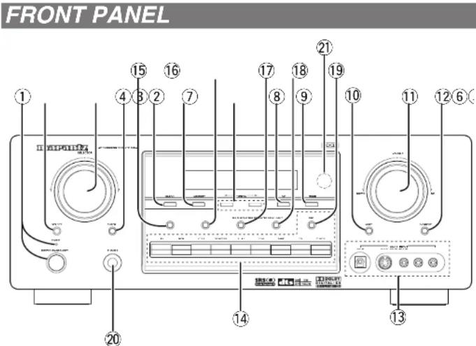
① POWER switch and STANDBY indicator When this switch is pressed once, the unit turns ON and the display illuminates. When pressed again, the unit turns OFF and the STANDBY indicator will be illuminated.
② SELECT (MULTI FUNCTION MODE SELECT) button
Press this button to change the mode of the MULTI FUNCTION control dial. i.e. Surround Sound Fields, Tone Control & Set Up Menu.
③ SURROUND MODE Selector & MULTI FUNCTION control dial
This dial changes surround modes & Tone Controls sequentially, and allows you to enter the OSD menu system.
④ ENTER (MULTI FUNCTION ENTER) button
Press this button to enter the setup, which you have chosen by the MULTI FUNCTION dial.
5 CLEAR button
Press this button to cancel the station-memory setting mode or preset scan tuning. (See page 28)
⑥ MEMORY button
Press this button to enter the timer preset memory numbers or station names. (See page 28)

TUNING Down)

Press these buttons to change the frequency or the preset number. (See page 28)
F/P (Frequency / Preset) button
During reception of AM or FM, you can change the function of the UP/DOWN buttons for scanning frequencies or selecting preset stations by pressing these buttons. (See page 28)
9 MODE button
Press this button to select the auto stereo mode or mono mode when the FM band is selected. The "AUTO" indicator lights in the auto stereo mode. (See page 28)
MUTE button
Press this button to mute the output to the speakers. Press it again to return to the previous volume level.
VOLUME control knob
Adjusts the overall sound level. Turning the control clockwise increases the sound level.
S- (Source) DIRECT button
When this button is pressed, the tone control circuitry is bypassed as well as Bass Management.
Notes:
- The surround mode is automatically switched to AUTO when the source direct function is turned on.
- Additionally, Speaker Configurations are fixed automatically as follows.
Front SPKR = Large, Center SPKR = Large
Surround SPKR = Large, Subwoofer = On
AUX1 input jacks
These auxiliary video/audio and optical digital input jacks accept the connections of a camcorder, portable DVD, game etc.
14 (19) INPUT FUNCTION SELECTOR buttons (AUDIO/VIDEO)
These buttons are used to select the input sources. The video function selector, such as TV, DVD, VCR1, DSS and AUX1, selects video and audio simultaneously.
Audio function sources such as CD, TAPE, CDR/ MD TUNER and AUX2 may be selected in conjunction with a Video source.
This feature (Sound Injection) combines a sound from one source with a picture from another.
Choose the video source first, and then choose a different audio source to activate this function.
Press the TUNER button to switch between FM and AM.
Press these buttons to select speakers systems A and/or B.
16 MULTI (Multi Room) button
Press this button to activate the Multiroom system. MULTI ^ 串 indicator will be illuminated in the display.
MULTI SPEAKER button
Press this button to activate the Multiroom Speaker system. "MULTI" indicator will be illuminated in the display.
18 7.1CH IN button
Press this button to select the output of an external multichannel decoder.
AUX2 button
This button is used to select the AUX2 (L/R Input of 7.1 CH.IN).
20 HEADPHONE jack for stereo headphones
This jack may be used to listen to the SR8400's output through a pair of headphones. Be certain that the headphones have a standard 1 / 4^ stereo phono plug. Note that the main room speakers will automatically be turned off when the headphone jack is in use.
Notes:
- When using headphones, the surround mode will change to STEREO and TruSurround (TS) headphones by SURROUND MODE selector.
- The surround mode returns to the previous setting as soon as the headphone plug is removed from the jack.
21 INFRARED receiving sensor window
This window receives infrared signals for the remote control.
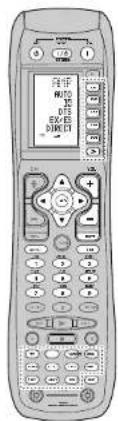
FL DISPLAY
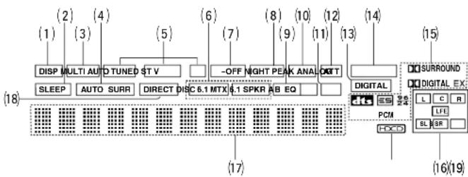
(1) DISP(Display Off) indicator
This indicator is illuminated when the SR8400 is in the display off condition.
(2) SLEEP timer indicator
This indicator is illuminated when the sleep timer function in the main-room is in use.
3 Multi-room system indicator
This indicator is illuminated when the multi-room system is active.
(4) AUTO SURR (Auto Surround mode) indicator
This indicator is illuminated to show that the AUTO SURROUND mode is in use.
(5) TUNER's indicators
AUTO: This Indicator illuminates when the tuner's Auto mode is in use.
TUNED: This indicator illuminates when a station is being received with sufficient signal strength to provide acceptable listening quality.
ST(Stereo): This indicator illuminates when an FM station is being tuned into stereo condition.
(6) DTS-ES mode indicators (DISC6.1, MTX6.1)
These indicators will illuminate to show the DTS-ES decoding mode (Discrete 6.1 or Matrix 6.1).
(7) V(video)-OFF mode indicator
This indicator is illuminated when the Video-OFF function is active.
(8) NIGHT mode indicator
This indicator is illuminated when the SR8400 is in the Night mode, which reduces the dynamic range of digital program material at low volume levels.
(9) SPKR (speaker) AB indicator
Active speaker system will be illuminated by this indicator.
(10) PEAK indicator
This indicator is a monitor for an analog audio input signal. If the selected analog audio input signal is greater than the capable level of internal processing, this will illuminate. If this happens, you should press the ATT button on the remote.
(11) EQ mode indicator
This indicator is illuminated when the HT-EQ function is active.
12 ATT (Attenuation) Indicator
This indicator is illuminated when the attenuation function is active.
(13) DIGITAL Input Indicator
This indicator lights when a digital input has been selected.
(14) ANALOG input indicator
This indicator is illuminated when an analog input source has been selected.
(15) SIGNAL FORMAT Indicators
DIGITAL, EX, SURROUND, dts, ES, 96/24, PCM
When the selected input is a digital source, some of these indicators will be illuminated to display the specific type of signal in use.
(16) ENCODED CHANNEL STATUS indicators
These indicators display the channels that are encoded with a digital
input signal. If the selected digital input signal is Dolby Digital 5.1ch or DTS 5.1ch, "L", "C", "R", "SL", "SR" and "LFE" will be illuminated. If the digital input signal is 2 channel PCM-audio, "L" and "R" will be displayed.
If Dolby Digital 5.1ch signal with Surround EX flag or DTS-ES signal comes in, "L", "C", "R", "SL", "S", "SR" and "LFE" will be illuminated.
(17) Main Information Display
This display shows messages relating to the status, input source, surround mode, tuner, volume level or other aspects of unit's operation.
18 DIRECT (Source direct) indicator
This indicator is illuminated when the SR8400 is in the SOURCE DIRECT mode.
(19) HDCD indicator
When HDCD signal is decoded, this indicator will light up.
REAR PANEL
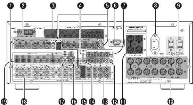
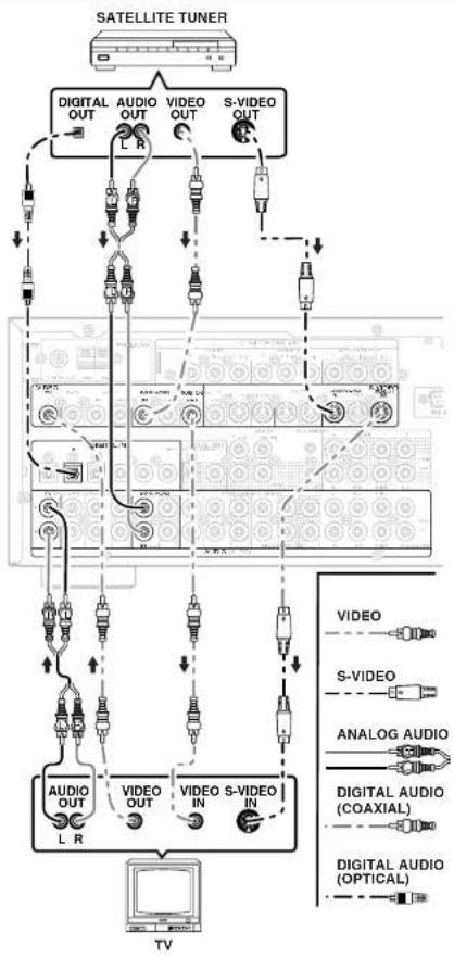
VIDEO IN/OUT (TV, DVD, VCR1, DSS/VCR2)
These are the video inputs and outputs. There are 4 video inputs and 2 video outputs and each one includes both composite video and S-video configurations. Connect VCRs, DVD players, and other video components to the video inputs. S-video sources can be viewed through the S-video outputs, and composite sources can only be viewed through the composite output. The 2 video output channels can be used to be connected to video tape recorders for making recordings.
FM antenna terminal (75 ohms)
Connect an external FM antenna with a coaxial cable, or a cable network FM source.
AM antenna and ground terminals
Connect the supplied AM loop antenna. Use the terminals marked "AM" and "GND". The supplied AM loop antenna will provide good AM reception in most areas. Position the loop antenna until you hear the best reception.
COMPONENTVIDEOINPUT/OUTPUT
If your DVD player or other device has component video connectors, be sure to connect them to these component video connectors on the SR8400. The SR8400 has two component video input connectors to obtain the color information (Y, C#, C#) directly from the recorded DVD signal or other video component and one component video output connector to output it directly into the matrix decoder of the display device.
By sending the pure DVD component video signal directly, the DVD signal forgoes the extra processing that normally would degrade the image. The result is vastly increased image quality, with incredibly life like colors and crisp detail.
4 FLASHER IN (Flasher input terminal)
This terminal is to control the unit from each zone. Connect the control signal from a Keypad, etc.
5 MONITOR OUT
This is a monitor output and each one includes both composite video and S-video configurations. When connecting two video monitors or televisions, be aware that the OSD Interface can be used with both MONITOR OUT connections.
6 RS-232C
The RS-232C port is to be used in conjunction with an external controller to control the operation of the SR8400 by using an external device. The RS-232C port may also be used in the future to update the operating software of the SR8400 so that it will be able to support new digital audio formats and the like as they are introduced.
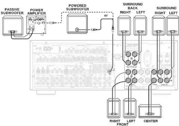
7 Preamp Outputs (L, R, SL, SR, SBL, SBR, C)
Jacks for L(front left), R (front right), C (Center), SL (surround left), SR (surround right), SBL (surround back left) and SBR (surround back right). Use these jacks for connection to external power amplifiers.
AC INLET
Plug the supplied power cord into this AC INLET and then into the power outlet on the wall. SR8400 has to be powered by 120 V AC only.
AC OUTLETS
Connect the AC power cables of components such as a DVD and CD player to these outlets. SWITCHED and UNSWITCHED outlets are provided. The one marked SWITCHED provides power only when the SRB400 is turned on and is useful for components which you use every time you play your system.
The one marked UNSWITCHED is always live as long as the SR8400 is plugged into a live outlet. A component connected here may be left on permanently, or may be switched off with via its own power switch.
Caution:
In order to avoid potential turn-off thumps, anything plugged into these outlets should be powered up before the SRX400 is turned on.
- The capacity of this AC outlet is 120W. Do not connect devices that consume electricity more than the capacity of these AC outlets. If the total power consumption of the connected devices exceeds the capacity, the protection circuit shuts down the power supply.
10 Speaker outputs terminals
Seven terminals are provided for the front (A) left, front (A) right, front (B) left, front (B) right, front center, surround left and surround right speakers.
1 Speaker outputs terminals (for multi room or surround back)
Two terminals are provided for the front the left, and right speakers for multi room (2nd zone) or surround back.
Subwoofer Output
Connect this jack to the line level input of a powered subwoofer. If an external subwoofer amplifier is used, connect this jack to the subwoofer amplifier input. If you are using two subwoofer, either powered or with a 2 channel subwoofer amplifier, connect a "V" connector to the subwoofer output jack and run one cable from it to each subwoofer amplifier.
13 7.1 CHANNEL or AUX2 INPUT
By connecting a DVD Audio player, SACD multichannel player, or other components that has a multichannel port, you can playback the audio with 5.1 channel or 7.1 channel outputs.
DC TRIGGER output terminal
Connect a device that needs to be triggered by DC under certain conditions (screen, power strip, etc...) Use the system OSD setup menu to determine the conditions by which these jack will be active.
Note:
- This output voltage is for (status) control only. It is not sufficient for drive capability.
15 Multiroom Outputs (Audio L&R, Video)
These are the audio and video output jacks for the Multi zone (Multi room).
Connect these jacks to optional audio power amplifiers or video display devices to listen and view the source selected by the multiroom system in a remote room.
16 MULTI ROOM REMOTE IN/OUT terminals
IN: Connect to a multi-room remote control device, available from your Marantz dealer. OUT: Connect to the Marantz component equipped with remote control (RC-5) terminals in Multi zone (Multi room).
17 REMOTE CONT. IN/OUT terminals
Connect to a Marantz component equipped with remote control (RC-5) terminals.
13 AUDIO IN/OUT (CD, TAPE, CD-R, TV, DVD, VCR1, DSS/VCR2)
These are the analog audio inputs and outputs. There are 7 audio inputs (4 of which are linked to video inputs) and 4 audio outputs (2 of which are linked to video outputs). The audio jacks are nominally labeled for cassette tape decks, compact disc players, DVD players and etc.... The audio inputs and outputs require RCA-type connectors.
DIGITAL INPUT (Dig.1-6) OUTPUT (coaxial, optical)
These are the digital audio inputs and outputs. There are 3 digital inputs with coaxial jacks, 3 with optical jacks.
The inputs accept digital audio signals from a compact disc, LD, DVD, or other digital source component.
For digital output, there is 1 coaxial output and 1 optical output.
The digital outputs can be connected to MD recorders, CD recorders, DAT decks, or other similar components.
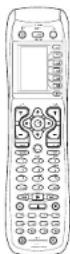
REMOTE CONTROLLER RC1400
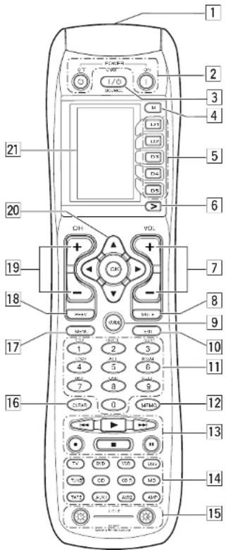
NAMES AND FUNCTIONS
Infrared Transmitter and Learning Sensor
This transmitter emits infrared light. Press the buttons while pointing the transmitter towards the infrared receiver window of the SR8400 or other AV equipment. Be sure to also point towards other remote controls when using the learning function.
2 POWER ON and OFF buttons
(When AMP mode is selected)
These buttons are used to turn the SR8400 on or off.
3 SOURCE ON/OFF button
This button is used to turn a specific source (such as a DVD player) on or off independently from the rest of the system.
M (Mode) button
This button is used to program Macros. Pressing this button switches between Normal mode and Macro mode.
The > button is used to move to the next page. Up to 20 programs (4 pages) can be made. Holding down the M button for three seconds or more switches to the Setup mode, where the Setup menu is shown on the LCD. The Setup menu has four pages, and the > button is used to move to the next page. Pressing the > button from page 4 returns you to page 1.
5 D1 to D5 (Direct) buttons
Five types of direct operations can be performed for each of the 12 source buttons such as the DVD, television, amplifier, and other AV equipment. The pages can be switched, so 4 pages × 5 types = 20 operations can be performed for a single source. The text display can also be changed.
6 > (Page) button
This button is used to switch pages for the Direct button. The current page is shown on the LCD.
VOL (Volume) button
This button is used to adjust the volume for the amplifier and television.
Note:
Set the AMP mode to use this button with the SR8400.
MUTE button
This button is used to mute the audio for the SR8400 and television.
Note:
Set the AMP mode to use this button with the SR8400.
9GUIDEButton
This button is used to display the menus for the DVD player. DSS (satellite broadcasting tuned), or other AV equipment.
10 EXIT button
(when AMP mode is selected)
This button is used to cancel settings in the setup menu.
11 Numeric buttons
These buttons are used to switch between 0 to 9 of the source components. If the source is set to the amplifier, these buttons are used to perform operations.
(when AMP mode is selected)
(1) TEST button
Used to enter the test tone menu.
(2)CHSEL.(channelselect)button
Used to call up SETUP MAIN MENU and adjust speaker levels of 7.1 ch input level.
(3) SURR (surround) button
Used to select the surround mode.
(4)Z.1CH IN button
Press this button to select the output of an external multi channel decoder.
(5) ATT button
When the input signal is too high and the voice distorts even by throttling the SR8400 VOLUME control, turn on this function. "ATT" is indicated when this function is activated.
The input level is reduced. Attenuator is invalid for use with the output signal of "REC OUT".
Note:
This function is unavailable during the digital input is selected.
(6)SPK-AB button
Speaker mode is switched in the following sequence.
A→B→A+B→off
(7)DISP. button
Selects the display mode for the front display of the SRB400.
(8)Osp button
When this button is pressed, the current setting are displayed on the TV monitor.
(9) SLEEP (sleep timer) button
This button is used for setting the sleep timer. It can be operated the same way as the button in unit.
12 MEMO button
This button is used to store settings to memory or program a source.
13 CONTROL button
Phases buttons are used when operating the PLAY, STOP, PAUSE, and other commands of a source.
Note:
This button is unavailable for the SR8400.
Theses buttons are used.
your A/V Receiver / amplifier. Each time a source button is pressed, the remote control changes to the source which was pressed.
This remote control can control 12 types of equipment. To change the A/V Receiver amplifier source, press this button twice within two seconds. The signal is sent when it is pressed the second time.
Note:
- Select the AMP as the source to use this remote controll with the SR8400.
15 LIGHT 1 and 2 buttons
Pressing these buttons will light up the LCD and its buttons. This lighting time can be set. If the lighting time is set to 0 seconds, the backlight turns on only while this button is pressed. The operations for LIGHT 1 and 2 are Identical.
16 CLEAR button
This button is used to erase the memory or program of a source.
17 MENU button
(when AMP mode is selected)
This button is used to call up the SETUP MAIN MENU of the SR8400.
PREV (Previous) button
This button is used to return to the previous channel on the television or other device.
Note:
This button is unavailable for SR8400.
CH(Channel) button
This is used to change channels.
CURSOR buttons
These buttons are used when controlling the cursor of the SR8400, DVD, or other AV equipment.
21 LCD
Information about the sources and modes are shown on the LCD.
LCD INDICATORS
Information about currently selected source and direct code names are displayed on the LCD.
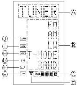
Source Name Indicator
This displays the name of the selected source, such as DVD, television, or other AV equipment (up to five characters).
Direct Button Name indicator
This displays up to 20 types of button names for each source. (up to six characters)
Page Indicator
This displays the current page position.
Transmission indicator
This lights up when the remote control is sending a signal.
USEIndicator
This is displayed under normal operation.
Battery Level indicator
This is displayed when the battery level is low.
TIMER Indicator
This is displayed when the macro timer is set.
MACRO indicator
This is displayed when the remote control is in macro programming mode.
① NAMEindicator
This is displayed when the remote control is in renaming mode.
LEARN Indicator
This is displayed when the remote control is in learning mode.
REMOTE CONTROL RANGE
The distance between the transmitter of the remote control and the IR SENSOR of the SR8400 should be less than 5 meters. If the remote control is pointed in a direction other than the IR SENSOR or if there is an obstacle between them, use of the remote control may not be possible.
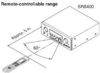
Remote control unit (RC1400)
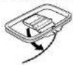
LOADING BATTERIES
The life of the batteries used with the remote control is about 4 months with normal use. Also be sure to replace batteries earlier when you notice that they are getting weak.
- Remove the back cover.

- Insert the new batteries (AAA type) with correct (+) and (-) polarity.
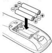
3. Close the cover until it clicks.

Note:
Do not use old batteries and new batteries together. This can result in corrosion or leakage of battery fluid.
The supplied manganese batteries are for checking operation. Usage of alkaline batteries is recommended.
When discarding batteries, be sure to follow the local regulations for your area. Do not put batteries in a fire.
BATTERY REPLACEMENT INTERVAL
Under normal usage, alkaline batteries last approximately four months. When the batteries wear out, a battery mark is displayed on the LCD. Although the remote control can still be used when the battery mark is displayed, the batteries should be replaced as soon as possible. The LCD eventually starts to flash when buttons are pressed, the remote control will be unable to transmit signals or learn codes.
This remote control uses non-volatile memory so that the learned codes and macro programs are retained even if the batteries are removed.
Reset the clock after replacing the batteries.
Safety Precautions for Batteries
Be sure to always observe the following precautions to prevent fluid leakage, overheating, fire, breakage, accidental ingestion, and other accidents.
- If the batteries are left unused for a long period of time, the battery fluid may leak or the batteries may corrode.
- Do not use the batteries in the remote control with the plus and minus polarity reversed.
- Do not attempt to recharge, heat, or disassemble the batteries. Do not put the batteries in a fire.
- Do not use the remote control with old batteries or worn-out batteries inserted.
- Do not use different types of batteries or mix old and new batteries in the remote control.
- If the remote control is not operating properly, replace the batteries with new ones.
If any of the batteries are leaking, completely wipe up all leaked battery fluid, and then replace the batteries with new ones.
SETTING THE TIME
Example: Setting to 6:20PM (18:20)
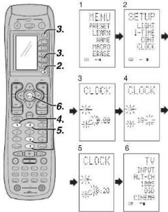
When you bought this remote control and insert the batteries to the remote control at first, the steps 1 to 3 are skipped.
Starts from step 4 to set the time.
- Hold down the M button for three seconds or more.
The menu is displayed. - Press the > button once. This displays second page (
- Press the D4 (CLOCK) direct button. The indicator blinks and the clock indicator displays 0:00 .
- Press the 1 and 8 numeric button to set the hour Indicator.
The hour indicator displays '18. The minute indicator binks "
- Press the 2 and 0 numeric button to set the minute indicator.
The minute indicator displays "20". - Press the OK cursor button to start the clock. The clock starts from 0 second at the time that was set and return to normal (USE) mode.
Whenever the batteries are replaced, the clock shows 00:00. Please reset the clock. (The time setting is not backed up.)
CHECKING THE TIME
To check the time, hold down the > button for three seconds or more. The current time is displayed for five seconds.
Note
Although the remote control uses a quartz clock, the time may become out of sync over the course of operation. Be sure to correct the clock from time to time.
GENERAL INFORMATION OF RC1400 TO SR8400
To control the SR8400 by your RC1400, you have to select the device AMP or TUNER by pressing the function selector button. Please refer below for the details in AMP and TUNER mode.
AMP MODE
| SOURCE ON/OFF Turns the SR8400 on and off | |
| POWER ON Turns the SR8400 on | |
| POWER OFF Turns the SR8400 off | |
| D1 - D5 / > (Page) (Refer to page vi) | |
| VOL +/- Adjust the over all sound level | |
| MUTE Decreases the sound temporarily | |
| Cursor Move the cursor for setting in"On screen display" mode | |
| OK Enter the "On screen display" | |
| Confirms the setting in "On screen display" mode | |
| MENU Displays the current setting on the monitor | |
| EXIT Exits from SETUP MENU | |
| TEST (1) Enter the best tone menu | |
| CH.SEL (2) Call up SETUP MENU and adjusts speaker levels or 7.1ch input level | |
| SURR (3) Selects the surround mode | |
| 7.1CH (4) Selects the 7.1CH IN | |
| ATT (5) Reduces the input level | |
| SPK-AB (6) Selects the speaker system | |
| DISP (7) Changes the front display mode | |
| OSD (8) Selects the "On screen display" on anc off | |
| SLEEP (9) Sets the sleep timer function | |
| Function selector Selects a particular source component |
TUNER MODE
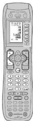
| D1 - D5 / >Page? (Refer to page vi) | |
| CH +/- Selects a preset station up and down | |
| GUIDE | Selects the "Frequency direct input" |
| 0-9 Input the numeric | |
| MEMO | Enter the tuner preset memory numbers |
| CLEAR | Clears the inputting |
| TUNER | Selects a frequency band |
CONNECTIONS
SPEAKER PLACEMENT
The ideal surround speaker system for this unit is 7-speaker systems, using front left and right speakers, a center speaker, surround left and right speakers, a surround back left and right speakers, and a subwoofer.
For best results we recommend that all front speakers be of the same type, with identical or similar driver units. This will deliver smooth pans across the front sound stage as the action moves from side to side.
Your center channel speaker is very important as over 80% of the dialog from a typical motion picture emanates from the center channel.
It should possess similar sonic characteristics to the main speakers. Surround channel speakers need not be identical to the front channel speakers, but they should be of high quality.
The surround center speaker is useful for playback of Dolby Digital Surround EX or DTS-ES. One of the benefits of both Dolby Digital and DTS is that surround channels are discrete full range, while they were frequency limited in earlier "Pro Logic" type systems.
Bass effects are an important part of home theater. For optimal enjoyment a subwoofer should be used as it is optimized for low frequency reproduction. If you have full range front speakers, however, they may be used in place of a subwoofer with proper setting of the switches in the menu system.
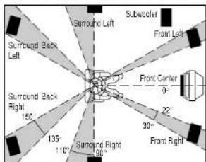
Front left and right speakers
We recommend to set the front L and R speakers with 45-60 degrees from the listening position. Center speaker
Align the front line of the center speaker with the front L/R speakers. Or place the center speaker a little backward from the line.
Surround left and right speakers
When the SRB400 is used in surround operation, the preferred location for surround speakers is on the side walls of the room, at or slightly behind the listening position.
The center of the speaker should face into the room.
Surround back left and right speakers
Surround back speakers are required when a full 7.1-channel system is installed.
Speakers should be placed on a rear wall, behind the listening position.
The center of the speaker should face into the room.
Subwoofer
We recommend using a sub-woofer to have maximum bass effect. Sub-woofer bears only low frequency range so you can place it any where in the room.
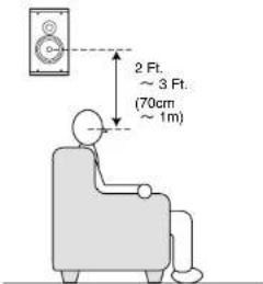
HEIGHT OF THE SPEAKER UNITS
Front left and right speakers, and a center speaker Align the tweeters and mid-range drivers on the three front speakers at the same height, as best as possible.
Surround left and right speakers, and surround back speaker
Place the surround left, right and surround back speakers higher than your ears by about 2 Ft. - 3 Ft.(70cm - 1m). Also place the speakers at the same height, sa best as possible.
Note:
Use magnetically-shielded speakers for front left, right and the center speakers when the speakers are installed near the TV and the TV is a monitor type.
CONNECTING SPEAKERS
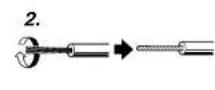
CONNECTING SPEAKER WIRE
- Strip away approx. 3/8 inch (10 mm) of wire insulation
- Twist the bared wire ends tight, to prevent short circuits.
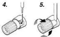
- Loosen the knob by turning it counterclockwise.
- Insert the bare part of the wire into the hole in side of each terminal.
- Tighten the knob by turning it clockwise to secure the wire.


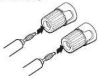
CONNECTING BANANA PLUG
Banana plug connections are also possible. Tighten the knob by turning clockwise and insert the banana plug.
Caution:
- Be sure to use speakers with the specified impedance as shown on the rear panel of this unit.
To prevent damage to circuitry, do not let the bare speaker wires touch each other and do not let them touch any metal part of this unit.
Do not touch the speaker terminals when the power is on. It may cause you to receive an c - Do not connect more than one speaker cable to one speaker terminal. Doing so may damage this unit.
Note:
- Be sure to connect the positive and negative cables for the speaker properly. If they are mis-connected, the signal phase will be reversed and the signal quality will be corrupted.
CONNECTING A SUBWOOFER
Use the PRE OUT SUBWOOFER jack to connect a powered subwoofer (power amplifier built in). If your subwoofer is a passive type (power amplifier is not built in), connect a monaural power amplifier to the PRE OUT SUBWOOFER jack and connect the subwoofer to the amplifier.
CONNECTING AUDIO COMPONENTS
The output audio signal from the TAPE OUT jack and the CD-R/MD OUT jack is the same signal which is currently selected.
Caution:
- Do not connect this unit and other components to mains power until all connections between components have been completed.
Notes:
- Insert all plugs and connectors securely. Incomplete connections may make noise.
- Be sure to connect the left and right channels properly.
Red connectors are for the R (right) channel, and white connectors are for the L (left) channel.
- Be sure to connect input and output properly.
Refer to the instructions for each component that is connected to this unit.
- Do not bind audio/video connection cables with power cords and speaker cables this will result in generating a hum or other noise.
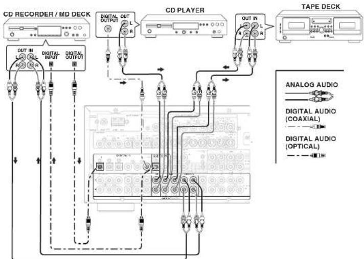
CONNECTING DIGITAL AUDIO COMPONENTS
- There are 6 digital inputs, 3 coaxial jacks and 3 optical jacks, on the rear panel. You can use these jacks to input PCM, Dolby Digital and DTS bitstream signals from a CD, DVD, or other digital source components.
There is one digital output coaxial jack and one optical output jack on the rear panel. These jacks can be connected to a CD recorder-, or a MD deck inputs, respectively. - Refer to the Instructions for each component. To setup the digital audio format of DVD player, or other digital source's connected to digital input jacks.
- Use fiber optical cables (optical) for DIG-1,2,3 input jacks. Use 75 ohms coaxial cables (for digital audio or video) for DIG-4,5,6 input jacks.
- You can designate the input for each digital input/output jacks according to your component. See page 18.
Notes:
- There is no Dolby Digital RF input jack. Please use an external RF dcmodulator Dolby Digital decoder when connecting the Dolby Digital RF output jack of the video disc player to the digital input jack.
- The digital signal jacks on this unit conform to the EIA standard. If you use a cable that does not conform to this standard, this unit may not function properly.
Each type of audio jack works independently. Signals input through the digital and analog jacks are output through the corresponding digital and analog jacks, respectively.
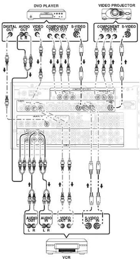
CONNECTINGVIDEOCOMPONENTS
VIDEO.S-VIDEO,.COMPONENTJACKS
There are 3 types of video jacks on the rear panel.VIDEO jack
The video signal for the VIDEO Jacks is the conventional composite video signal.
S-VIDEO jack
The video signal is separated into luminance (Y) and color (C) signals for the S-VIDEO jack. The S-VIDEO signals enable high-quality color reproduction. If your video component has an S-VIDEO output, we recommend to use it. Connect the S-VIDEO output jack on your video component to the S-VIDEO input jack on this unit.
Component jack
Make component video connections to a TV or monitor with component inputs to produce higher quality video images. Use a component video cable or 3 video cords to connect the component video cut jacks on the SR8400 to the monitor.
Notes:
- Be sure to connect the left and right audio channels properly.
Rcd connectors are for the R (right) channel, and white connectors are the for L (left) channel. - Be sure to connect the inputs and outputs of the video signals properly.
- If you connect the S-VIDEO or component signal to the S-VIDEO or component jack on this unit, it is not necessary to connect the conventional video signal to the VIDEO (composite) jack. If you use both video inputs, this unit gives priority to the S-VIDEO signal.
Each type of video jack works independently. Signals input to theVIDEO (composite) and S-VIDEOjacks or component are output to the correspondingVIDEO (composite) and S-VIDEOor component jacks, respectively. - This unit has the "TV-AUTO ON/OFF" function to turn the TV ON or OFF automatically, by sensing the incoming video signal from the VIDEO racks.
- You may need to setup the digital audio output format of your DVD player, or other digital source components. Refer to the instructions of the each component connected to the digital input jacks.
There is no Dolby Digital RF input jack. Please use an external RF demodulator with a Dolby Digital decoder to connect a video disc player which has a Dolby Digital RF output jack to the digital input jack on this unit.
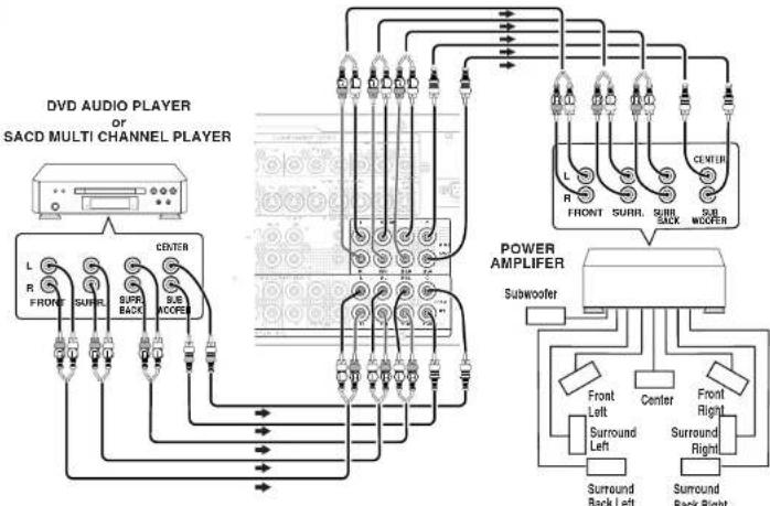
CONNECTING AN EXTERNAL POWER AMPLIFIER
CONNECTING MULTI CHANNEL AUDIO SOURCE
The 7.1CH INPUT jacks are for multichannel audio source such as a SACD multichannel player; DVD audio player or external decoder. If you use these jacks, switch on the 7.1CH INPUT and set the 7.1CH INPUT level by using the SETUP MAIN MENU. See page 21.
The PREQUT Jacks are for connecting external power amplifiers.
Be sure to connect each speaker to the corresponding external power amplifier.
CONNECTING THE REMOTE CONTROL JACKS
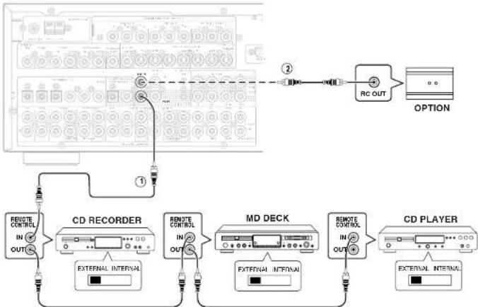
①
You can control other Marantz products through this unit with the remote control by connecting the REMOTE CONTROL terminals on each unit.
The signal transmitted from the remote control is received by the remote sensor on this unit. Then the signal is sent to the connected device through this terminal. Therefore you need to aim the remote signal only to the unit. Also, if a Marantz power amplifier (some models excluded) is connected to one of these terminals, the power amplifier's, power switch is synchronized with this unit's power switch.
Set the REMOTE CONTROL SWITCH on the units, other than the main unit to EXT.(EXTERNAL) for this feature.
2
Whenever external infrared sensors or similar devices are connected to RC-5 IN of the SR8400, be sure to always disable operation of the infrared sensor on the main unit by using the following procedure.
- Hold down the SELECT button and TV button on the front panel at the same time for five seconds.
- The setting "IR-ENABLE" is shown on the FL DISPLAY.
- Press the SELECT button to change this to "IR=DISABLE".
- Press the ENTER button. Once this setting is made, the infrared sensor on the main unit is disabled.
Note:
Be sure to set to "IR=ENABLE" when external infrared sensors or similar devices are not connected. Otherwise, the main unit will be unable to receive remote control commands.
5. To restore the original setting, perform steps 1 to 4 to set to "IF=ENABLE".
CONNECTING THE ANTENNA TERMINALS
ASSEMBLING THE AM LOOP ANTENNA
- Release the vinyl tie and take out the connection line.
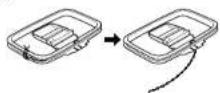
- Bend the base part in the reverse direction.
- Insert the hook at the bottom of the loop part into the slot at the base part.
- Place the antenna on stable surface.

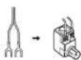
CONNECTING THE ANTENNA WIRE TO THE ANTENNA CONVERTER
Loosen the screws and fix the terminals of wire. Then tighten the screws with a screwdriver.
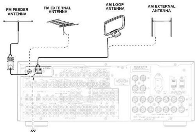
CONNECTING THE SUPPLIED ANTENNAS
Connecting the supplied FM feeder antenna
The supplied FM feeder antenna is for indoor use only.
During use, extend the antenna and move it in various directions until the clearest signal is received. Fix it with push pins or similar implements in the position that will cause the least amount of distortion. If you experience poor reception quality, an outdoor antenna may improve the quality.
Connecting the supplied AM loop antenna
The supplied AM loop antenna is for indoor use only.
Set it in the direction and position it to where you receive the clearest sound. Put it as far away as possible from the unit, televisions, speaker cables, and power cords.
If you experience poor reception quality, an outdoor antenna may improve the quality.
- Press and hold down the lever of the AM antenna terminal.
- Insert the bare wire Into the antenna terminal. 3. Release the lever.
CONNECTING AN FM OUTDOOR ANTENNA
Notes:
- Keep the antenna away from noise sources (neon signs, busy roads, etc.).
- Do not put the antenna close to power lines. Keep it well away from power lines, transformers, etc.
- To avoid the risk of lightning and electrical shock, grounding is necessary.
CONNECTING AN AM OUTDOOR ANTENNA
An outdoor antenna will be more effective if it is stretched horizontally above a window or outside.
Notes:
- Do not remove the AM loop antenna.
- To avoid the risk of lightning and electrical shock, grounding is necessary.
CONNECTING FOR THE MULTI ROOM
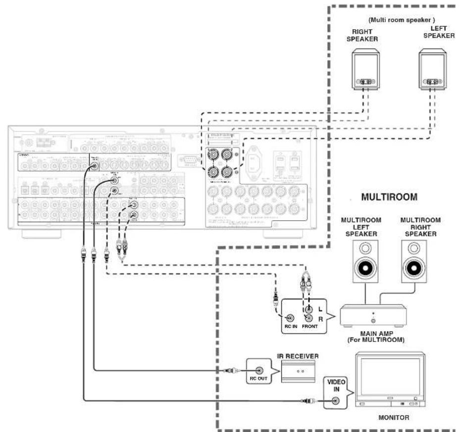
Note:
- You can use surround back speaker terminals as multi room speaker terminals when you use no surround back speaker.
SETUP
After all components are connected, initial setup must be performed.
To view the on-screen displays, make certain you have made a connection from the Monitor Out jack on the rear panel to the composite, S-video, component video input of your TV or projector. (see 13 page)
- Select the AMP mode on the remote control.
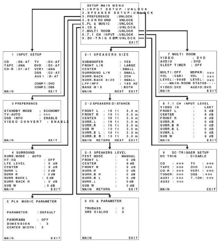
- Press the MENU button on the remote control to display the "SETUP MAIN MENU" of the OSD menu system. There are 9 items in the SETUP MAIN MENU. If you enter this menu from the MULTI dial on the front panel.
Press SELECT to show the "SETUP MENU" in the FL display and press the ENTER button. - Select a desired sub-muon with the oR tnsor buttons, and press the OK button to enter. The display will change to the selected sub-muon. You can lock the condition of setup to each sub-muon with the oR tnsor buttons.
Notes: If you desire to adjust any sub-menu, you need to set it to UNLOCKED. - If you desire to exit from this menu system, press the EXIT button (or SELECT button on the front panel), or move the cursor to EXIT and press the OK button.
1 INPUT SETUP (ASSIGNABLE DIGITAL INPUT AND COMPONENT VIDEO INPUT)
Six digital inputs can be assigned to a desired source.
Use this menu to select the digital input jack to be assigned to the input source.
- Select "INPUT SETUP" in SETUP MENU with Cursor button, and press OK button.
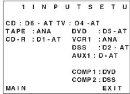
- To select the input source, press the or cursor buttons.
- To select the digital input jack, press the cursor buttons.
Select "Dx-AT" for Input sources, for automatic detection of the digital input signal condition. If there is not a digital signal present, but there is an analog signal present, the analog signal will be played.
Select "Dig x", when only a digital signal will be used. Select "ANA" for input sources for which no digital input jacks are used.
- To select the video source, select "COMP1" or "COMP2" by pressing the Cursor buttons, and press the Cursor buttons to select the video source to be assigned.
- After you complete this portion of the set up, move the cursor to MAIN with the Cursor buttons and press the OK button.
Notes:
- The TUNER and AUX2 are fixed to the analog input, and cannot be selected for any digital input.
- When a DTS-LD or DTS-CD is playing, this setup is not available. This is to avoid noise being generated from the analog input.
If "Dx-A" is selected and a DVD, compact disc or LD is fast-forwardsed during playback, decoded signals may produce a skipping sound. In such cases, change the setting to DIGITAL.
2 SPEAKER SETUP
After you have installed the SRB400, connected all the components, and determined the speaker layout, it is now time to perform the settings in the Speaker Setup menu for the optimum sound acoustics for your environment and speaker layout. Before you perform the following settings, it is important that you first determine the following characteristics:
2-1 SPEAKERS SIZE
When setting the speaker size in the SPEAKER SIZE sub-menu, use the guidelines given below. LARGE:
The complete frequency range for the channel you are setting will be output from the speaker. SMALL:
Frequencies of the channel you are setting lower than approx. 100Hz will be output from the subwoofer. If the Subwoofer is set to "NONE" and the front speakers are set to "Large," then the sound will be output from both the left and right speakers.
| 2-1 SPEAKERS SIZE | |
| SUBWOOFER | : YES |
| FRONT L/R | : LARGE |
| CENTER | : SMALL |
| SURROUND L/R | : SMALL |
| SURR. BACK | : 2CH |
| SURR. BACK SIZE | : SMALL |
| LPF/HPF | : 100 Hz |
| BASS MIX | : BOTH |
| MAI IN | NEXT EX I T |
- Select "SPEAKER SETUP" in SETUP MAIN MENU with ▲or Cursor button, and press the OK button.
- To select the each speaker, press the or cursor buttons.
- To select the setting of each speaker size, press the cursor buttons.
- After you complete this portion of the set up, move the cursor to "NEXT" with the or cursor buttons and then press the OK button to go to the next page.
SUBWOOFER:
YES:
Select when a subwoofer is connected. NONE:
Select when a subwoofer is not connected.
FRONT L/R
LARGE
Select if the front speakers are large. SMALL:
Select if the front speakers are small.
- If "NONE" is selected for the Subwoofer setting, then this setting is fixed to "Large."
CENTER
NONE:
Select If no center speaker is connected.
LARGE:
Select if the center speaker is large.
SELECT: Select if the center speaker is small.
SURROUND L/R
NONE:
Select if no surround left and right speakers are connected.
LARGE:
Select If the surround left and right speakers are large.
SMALL:
Select if the surround left and right speakers are small.
SURR. BACK
NONE: Select if no surround back left and right speakers are connected.
2CH: Select if the surround back left and right speakers are connected.
1CH: Select if the one surround back speaker is connected.
In this case, the audio signal is emitted form the Surround L output terminal.
Notes:
- If "None" is selected for the Surround L/R setting, then this setting is fixed to "None."
- You can use surround back speaker terminals as multi room speaker terminals when you use no surround back speaker. (See page 16)
SURR. BACK SIZE
LARGE
Select if the surround back speaker is large.
SMALL: Select if the surround back speaker is small.
Note:
- If "None" is selected for the Surround L_fR setting, then this setting is not available.
LPE/HPF
When you use a subwoofer, you can select the cutoff frequency for the small speakers used. Select one of the crossover frequency levels according to the size of the small speaker connected.
Select this when the bass speaker is about 12cm (4 3/4 inches).
100Hz
Select this when the bass speaker is about 10cm (3 15/16 inches).
120Hz:
Select this when the bass speaker is about 8 cm (3 3/16 inches).
Notes:
- Use the above comments as reference when adjusting.
- If S-Direct mode, 7.1CH Input is in use, this function does not take effect.
BASS MIX
- The bass mix setting is only valid when "LARGE" is set for the front speakers and "YES" is set for the subwoofer during stereo playback.
- When "BOTH" is selected, the low frequencies will be played through the main L&R, as well as the sub woofer.
In this playback mode, the low frequency range expand more uniformly through the room, but depending on the size and shape of the room, interference may result in a decrease of the actual volume of the low frequency range.
- By selecting "MIX", the low frequencies will play through the main L&R ONLY.
Note:
- LFE signals during playback of Dolby Digital or DTS, will be played through the subwoofer.
2-2 SPEAKERS DISTANCE
Use this parameter to specify the distance of each speaker's position from the listening position. The delay time is automatically calculated according to these distances.
Begin by determining the ideal or most commonly used seating position in the room.
This is important for the timing of the acoustics to create the proper sound space that the SR8400 and today's sound systems are able to produce.
Note: For speakers that you have selected "None" the Speaker Configuration sub-menu will not appear here. (There are several useful books and special DVD and LD's available to guide you through proper home theater configuration. If you are unsure, have your Marantz dealer perform the installation for you. They are trained professionals familiar with even the most sophisticated custom installations. Marantz recommends the WWW.CEDIA.ORG website for further information about this).
| 2-2 SPEAKERS DISTANCE | ||
| FRONT L : 10 ft 3.0 m | ||
| FRONT R : 10 ft 3.0 m | ||
| CENTER : 10 ft 3.0 m | ||
| SURR. L : 10 ft 3.0 m | ||
| SURR. R : 10 ft 3.0 m | ||
| SUB W : 10 ft 3.0 m | ||
| SURR. B L : 10 ft 3.0 m | ||
| SURR. B R : 10 ft 3.0 m | ||
| MAIN RETURN NEXT EXIT |
- To select each speaker, press the or Cursor buttons.
- To set the distance for each speaker, press the cursor buttons.
- After you complete this portion of the set up, move the cursor to "NEXT" with the or cursor buttons and then press the OK button to go to the next page.
FRONT L:
Set the distance from the front left speaker to your normal listening position between 1 and 30 feet in 1.0 foot intervals (0.3 to 9 meters in 0.3-meter intervals).
FRONT B:
Set the distance from the front right speaker to your normal listening position between 1 and 30 feet in 1.0 foot intervals (0.3 to 9 meters in 0.3-meter intervals).
CENTER
Set the distance from the center speaker to your normal listening position between 1 and 30 feet in 1.0 foot intervals (0.3 to 9 meters in 0.3-meter intervals).
SURB.L:
Set the distance from the surround left speaker to your normal listening position between 1 and 30 feet in 1.0 foot intervals (0.3 to 9 meters in 0.3-meter Intervals).
SUBB.R:
Set the distance from the surround right speaker to your normal listening position between 1 and 30 feet in 1.0 foot intervals (0.3 to 9 meters in 0.3-meter intervals).
SUBW
Set the distance from the subwoofer to your normal listening position between 1 and 30 feet in 1.0-foot intervals
(0.3 to 9 meters in 0.3-meter intervals).
Set the distance from the surround back left speaker to your normal listening position between 1 and 30 feet in 1.0-foot intervals (0.3 to 9 meters in 0.3-meter intervals).
SURR.BR:
Set the distance from the surround back right speaker to your normal listening position between 1 and 30 feet in 1.0-foot intervals (0.3 to 9 meters in 0.3-meter Intervals).
Notes
For the speakers that you have selected "None", the Speaker Size menu will not appear.
- The setting for Surr.Back I and Surr.Back R appears if you set for it to, two surround back speakers in the Speaker Size menu.
- The setting of Surr. Back appears if it is set for one surround back speaker in the Speaker Size menu.
2-3 SPEAKERS LEVEL
Here you will set the volume for each speaker so that they are all heard by the listener at the same level. We recommend using a SPL (Sound Pressure Level) meter, when available.
Note.
The speaker level settings are not available in 7.1 channel input mode and S-Direct mode.
| 2 - 3 SPEAKERS LEVEL | |
| T EST MODE : MANUAL | |
| FRONT L : 0 dB | |
| CENTER : 0 dB | |
| FRONT R : 0 dB | |
| SURR.R : 0 dB | |
| SURR.BR : 0 dB | |
| SURR.BL : 0 dB | |
| SURR.L : 0 dB | |
| SUB W : 0 dB | |
| MAIN RETURN EX I T |
TEST MODE :
Selects "MANUAL" or "AUTO" for generating the mode of the test tone with the Cursor buttons.
If you select "AUTO", the test tone will be cycled through in a circular pattern which is Left Center Right Surround Back Right Surround Back Left Surround Left Subwoofer Left increments of 3 seconds for each channel.
Using the for cursor buttons, adjust the volume level of the noise from the speaker so that it is the same level for all the speakers.
If you select "MANUAL", adjust the output level of each speaker as listed below.
- When you move the cursor to FRONT L by pressing the v cursor button, the SR8400 will emit a pink noise from the front left speaker. Remember the level of this noise and then press the v cursor button.
(Note that this can be adjusted to any level between -10 and +10 dB in 1 dB intervals except the subwoofer setting. The subwoofer can be adjusted to any level between -15 and +10 dB in 1 dB intervals.)
The SR8400 will now emit the pink noise from the center speaker.
- Using the and Cursor buttons, adjust the volume level of the noise from the center speaker so that it is the same level as the front left speaker.
- Press the cursor button again. The SR8400 will now emit the pink noise from the front right speaker.
- Repeat steps 2 and 3 above for the front right and other speakers until all speakers are adjusted to the same volume level.
After you complete this portion of the set up, press the OK button, the cursor will move to "MAIN" and then press the OK button to go to SETUP MAIN MENU.
Notes:
- Speakers that you selected "None" for in the Speaker Size menu will not appear.
- The setting of Surr.Back L and Surr.Back R appears if you have set it for two surround back speakers in the Speaker Size menu.
- The setting of SurrBack appears if you have set it for one surround back speaker in the Speaker Size menu.
To adjust the speaker levels for 7.1-channel input sources, you will need to use the 7.1CHI-INPUT sub menu. (See page 21).
3 PREFERENCE
| 3 PREFERENCE | |
| STANDBY MODE : ECONOMY | |
| TV-AUTO : *** | |
| OSD INFO : ENABLE | |
| VIDEO CONVERT : ENABLE |
MAIIN
EXIT
- Select "PREFERENCE" in the SETUP MAIN MENU with the Cursor buttons, and press the OK button.
- To select a desired content, press the or cursor buttons.
STANDBY MODE:
When this function is set to "ECONOMY", you can reduce the power consumption when the unit is in the standby mode.
Note:
- TV-AUTO and RS-232C are disabled in the "ECONOMY" setting.
TV AUTO:
Select the TV AUTO ON/OFF function to enable or disable with the Cursor buttons. (refer to page 26)
OSD Info:
Select the OSD information function to enable or disable with the for cursor buttons.
If you select "ENABLE", the SR8400 will display the status of the feature (Volume up/down, input select, etc.) on the TV monitor. But if you do not desire this information, select "DISABLE".VIDEO CONVERT:
Select the VIDEO CONVERT function to enable or disable with the 一 _ 0 cursor buttons. (refer to page 22)
After you complete this portion of the set up, move the cursor to "MAIN" with the or cursor buttons and press the OK button.
| 4 SURROUND | |
| SURR_MODE: AUTO | |
| HT - EQ : OFF | |
| LFE LEVEL : 0 dB | |
| CENTER : 0 dB | |
| SURR L : 0 dB | |
| SURR R : 0 dB | |
| SURR BACK L : 0 dB | |
| SURR BACK R : 0 dB | |
| SUB W : 0 dB | |
| MAIN : EXIT |
- Select "SURROUND" in the SETUP MAIN MENU with the Cursor buttons, and press the OK button.
- To select a desired content, press the or cursor buttons.
SURR_MODE:
Select the desired surround mode with the cursor buttons.
HT-EQ
Select to active the HT-EQ with the or Cursor buttons.
The tonal balance of a film soundtrack will be excessively bright and harsh when played back over audio equipment in the home. This is because film soundtracks were designed to be played back in large movie theater environments. Activating the HT-EQ feature when watching a film made for movie theaters corrects this and restores the correct tonal balance.
The HT-EOF feature can be activated only while in Dolby Pro Logic Mode, or while decoding Dolby Digital or DTS encoded material.
LFE LEVEL:
Select the output level of the LFE signal included in the Dolby Digital signal or the DTS signal. Select 0 dB, -10 dB or OFF with the Cursor buttons.
CHANNEL LEVEL
CENTERLEVEL:
Set the effect level of the center speaker between
-10 and +10 dB level in 1 dB level intervals.
- If "None" was selected for the Center speaker setting, in the Speaker size set up menu, then this setting will not appear.
SURRLLEVEL:
Set the level of the Surround left speaker between -10 and +10dB level in 1 dB level intervals.
- If "None" was selected for the Surround left speaker setting, in the Speaker size set up menu, then this setting will not appear.
SUBBLEVEL:
Set the level of the Surround right speaker between -10 and +10dB level in 1dB level intervals.
- If "None" was selected for the Surround right speaker setting, in the Speaker size set up menu, then this setting will not appear.
SURB BACK L LEVEL:
Set the effect level of the Surround Back L (left) speaker between -10 and +10 dB level in 1 dB level intervals.
- If "None" was selected for the Surround back left speaker setting, in the Speaker size set up menu, then this setting will not appear.
SURR BACK R LEVEL:
Set the effect level of the Surround Back R (Right) speaker between -10 and +10dB level in 1 dB level intervals.
- If "None" was selected for the Surround back right speaker setting, in the Speaker size set up menu, then this setting will not appear.
SUBWLEVEL:
Set the effect level of the subwoofer speaker between -15 and +10 dB level in 1 dB level Intervals.
- If "None" was selected for the Subwoofer speaker setting, in the Speaker size set up menu, then this setting will not appear.
After you complete this portion of the set up, move the cursor to "MAIN" with the Aor Cursor buttons and press the OK button.
5 PL II (PRO LOGIC II) MUSIC PARAMETER
Pro Logic II-Music mode creates a rich and enveloping surround ambience from stereo sources such as CDs. In this mode, SRB400 includes three controls to fine-tune the soundfield as follows.
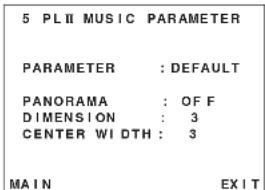
Select "PLII MUSIC" in the SETUP MAIN MENU with the Cursor buttons, and press the OK button.
PARAMETER:
Select“DEFAULT”or“CUSTOM”with the or cursor buttons.
If you select "CUSTOM", you can adjust three parameters as listed below.
PANORAMA:
Select the Panorama mode On or Off with theor cursor buttons.
Panorama wraps the sound of the front left and right speakers around you, for an exciting perspective.
DIMENSION
Set the Dimension level between 0 and 6 level in
1 level intervals with the or Nursor buttons. Adjust the soundfield either towards the front or towards the rear.
This can be useful to help achieve a more suitable balance from all the speakers with certain recordings.
CENTERWIDTH:
Set the Center width level between 0 and 7 in 1 level intervals with the cursor buttons.
Center Width allows you to gradually spread the center channel sound into the front left and right speakers.
At its widest setting, all the sound from the center is mixed into the left and right.
This control may help achieve a more spacious sound or a better blend for the front image.
If "None" was selected for the Center speaker setting, in the Speaker size set up menu, then this setting will not appear.
After you complete this portion of the set up, move cursor to "MAIN" with the Cursor buttons and press the OK button.
6 CS II (CIRCLE SURROUND II) PARAMETER
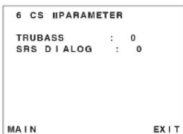
- Select "CS II" in the SETUP MAIN MENU with the or cursor buttons, and press the OK button.
- To Select desired contents as below, press the Cursor buttons.
TRUBASS:
Set the TRUBASS level between 0 and 6 level in 1 level interval with the or cursor buttons. TRUBASS produced by the speakers are an octave below the actual physical capabilities of the speakers adding exciting, deeper bass effects.
SRS DIALOG:
Set the SRS DIALOG level between 0 and 6 in 1 level intervals with the or cursor buttons. This can be popped out of the surround audio effects, allowing the listener to easily discern what the actors say.
If "NONE" was selected for the Center speaker setting, in the Speaker size set up menu, then this setting will not appear.
After you complete this portion of the set up, move cursor to 'MAIN' with the Cursor buttons and press the OK button.
7 MULTI ROOM
SR8400 has features in MULTI ROOM SYSTEM such as source selector, OSD information, sleep timer, Multi Room Speaker output and remote control.
You can set these feature in this sub-menu.
| 7 MULTI ROOM | ||
| VIDEO | : DVD | |
| AUDIO | : DVD | |
| SLEEP TIMER | OFF | |
| MULTI:OFF | MSPKR: *** | |
| VOL:VARI | VOL: *** | |
| LEVEL:-90dB | LEVEL: *** | |
| -----MAIN-ROOM | STATUS---- | |
| VIDEO:DVD | AUDIO:DVD | |
| MAIN | EXIT | |
- Select "MULTI ROOM" In the SETUP MAIN MENU with or Cursor button, and press the OK button.
- To Select desired contents, press or cursor button.
VIDEO:
Select the video source of the Multi-room output with Cursor buttons.
AUDIO:
Select the audio source of the Multi-room output with for nursor buttons.
SLEEP TIMER:
SLEEP timer function is available during the multiroom is active, set the time with or cursor buttons.
MULTI (MULTI ROOM):
To switch on the Multi-room output ON or OFF, press Cursor button.
VOL (VOLUME SETUP):
Select whether the Multi-room output level is variable or fixed with a Cursor buttons.
LEVEL (VOLUME LEVEL):
Adjust the Multi-room output level with or cursor buttons.
MSPKR (MULTI SPEAKER):
To switch on the Multi-speaker output ON or OFF, press Cursor buttons.
Note:
- This setting can be changed when the Surr Back is set "None" in 2-1 SPEAKER SIZE menu. When this setting is unavailable, "***" is displayed
VOL (VOLUME SETUP):
Select whether the Multi-speaker output level is variable or fixed with a Cursor buttons.
Note:
- This setting can be changed when the Sur Back is set "None" in 2-1 SPEAKER SIZE menu. When this setting is unavailable, "empty" is displayed.
LEVEL (VOLUME LEVEL):
Adjust the Multi-speaker output level with cursor button.
Note:
- This setting can be changed when the Surr Back is set "None" in 2-1 SPEAKER SIZE menu. When this setting is unavailable, "***" is displayed
MAIN ROOM STATUS:
Selected input source in the main room will be displayed.
Note
- If "VOLUME" is set to "FIXED", the multi-room output level cannot be adjusted from the second zone.
After you complete this portion of the set up, move the cursor to "MAIN" with or cursor buttons and press OK button.
87.1 CH INPUT LEVEL
This sub-menu is to adjust the speaker levels for 7.1-channel input sources.
Here you will adjust the volume for each channel so that they are all heard by the listener at the same level.
| 87.1 CH INPUT LEVEL | |
| VIDEO IN : LAST | |
| FRONT L : 0 dB | |
| CENTER : 0 dB | |
| FRONT R : 0 dB | |
| SURR.R : 0 dB | |
| SURR.B R : 0 dB | |
| SURR.B L : 0 dB | |
| SURR.L : 0 dB | |
| SUB W : 0 dB | |
| MAIN : EXIT |
- Select "7.1CH INPUT" in the SETUP MAIN MENU with the Cursor buttons, and press the OK button.
- To select "VIDEO IN", press or Cursor button.
- Using the Cursor buttons, select the video input source which is emitted from Monitor out in the 7.1 CH INPUT function. The input source is switched by pressing the or Cursor buttons as follows;
LAST TV DVD VCR1 DSS AUX1 V-OFF LAST
Notes:
- When select LAST, the source is set previous source before 7.1 CH INPUT function is activated.
-
When select V-OFF, no signal is emitted from monitor out terminal.
-
To Select desired channel, press the or cursor buttons.
-
Using the Cursor buttons, adjust the volume level of each channel.
- After you complete this portion of the set up, move the cursor to "MAIN" with the or cursor buttons and press the OK button.
Note:
These settings will be memorized to 7.1CH INPUT source.
9 DC TRIGGER SETUP
SR8400 has a DC trigger control jack, this is selectable to link with input functions for the main room or multi room.
- Select "DC-TRIG SETUP" in the SETUP MAIN MENU with ▲or Cursor button, and press the OK button.
- You can select MAIN ROOM, MULTI ROOM, REMOTE or DISABLE by pressing cursor buttons.
Note:
- REMOTE is available for the external control. The RC1400 cannot operate this function.
- To select desired input source, press ▲or cursor button.
- To set ON or OFF, press cursor button.
- After you complete this portion of the set up, move the cursor to "MAIN" with the cursor buttons and press the OK button.
SELECTING AN INPUT SOURCE
Before you can listen to any input media, you must first select the input source on the SR8400.
Example : DVD
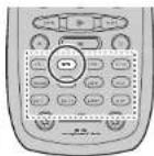
To select DVD, simply press the DVD button on the front panel or press the DVD button on the remote. After you have selected DVD, simply turn on the DVD player and play the DVD.
- As the input source is changed, the new input name will appear momentarily an OSD information on the video display. The input name will also appear in the display, on the front-panel.
- As the input is changed, the SR8400 will automatically switch to the digital input, surround mode, attenuation, and night mode status which were entered during the configuration process for that source.
- When an audio source is selected, the last video input used remains routed to the VCR1 & DSS/ VCR2 Outputs and Monitor Output. This permits simultaneous viewing and listening to different sources.
- When a Video source is selected, the video signal for that input will be routed to the Monitor Output Jacks and will be viewable on a TV monitor connected to the SRB400.
If a component video input is connected to the DVD or DSS component inputs, it will be routed to the Component Video Output. Make certain that your TV is set to the proper input to view the signal.
VIDEO CONVERT
When this function is activated, the video or S-video signal can be emitted from the video, S-video or component video output terminal. To activate this function, select VIDEO CONVERT In PREFERENCE menu and set ENABLE.
Notes:
- The component video signal is emitted only from component video output terminal.
When the video equipment is connected by component terminal, connect the monitor and SR8400 by the component terminal.
- This function is unavailable for the REC out terminal.
This function is unavailable for the still picture, fast forward and reverse playing of the video component.
- If the picture has a noise with this function, the combination of the monitor, SR8400 and the video component may be not compatible.
In this case,VIDEO CONVERT function must be set DISABLE.
Example.
Monitor is connected with the component.
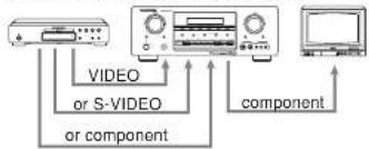
Monitor is connected with the video or S-video.
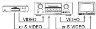
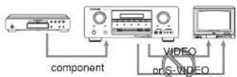
The signal cannot be converted from the component to the video or S-video.
Notes of OSD menu:
- The setup menu can be displayed through all video out (COMPONENT, S-VIDEO, VIDEO).
- The setting informations (e.g., volume setting) are displayed through all video out when theVIDEO CONVERT function are set ENABLE.
Note: no setting information is displayed when the signal is emitted from the COMPONENT IN to COMPONENT OUT.
- The setting informations (e.g. volume setting) are displayed through the S-VIDEO or VIDEO out when the VIDEO CONVERT function is set DISABLE. When the S-VIDEO and VIDEO outputs are used simultaneously, the setting informations are displayed through the S-VIDEO out only.
To select the surround mode during playback, turn the SELECT knob on the front panel.
(Using the remote control unit)
To select the surround mode, press the AMP button and press the > button until PAGE1 is displayed. Press the AUTO (D1) button.
ADJUSTING THE MAIN VOLUME
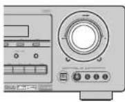
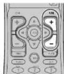
Adjust the volume to a comfortable level using the VOLUME control knob on the front panel or VOL + / - buttons on the remote.
To increase the volume, turn the VOLUME knob clockwise or press VOL + button on the remote. To decrease the volume, turn counterclockwise or press VOL - button on the remote.
Notes:
- The volume can be adjusted within the range of - to 18dB , in steps of 1dB .
However, when the channel level is set as described on page 19, if the volume for any channel is set at +1dB or greater, the volume cannot be adjusted up to 18dB .
(In this case the maximum volume adjustment range is ^*18 dB. Maximum value of channel level
ADJUSTING THE TONE (BASS & TREBLE) CONTROL.
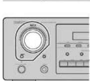
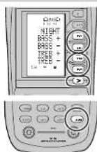
During a listening session you may wish to adjust the Bass and Treble Control to suit your listening tastes or room acoustics.
(Using the SR8400)
To change the selector mode, press the SELECT button, until "BASS" or "TREBLE" is shown on the front display.
Turn the SELECTOR knob to the desired level of tone control.
(Using the remote control unit)
To adjust the tone, press the AMP button and press the > button PAGE3 is displayed.
To adjust the bass effect, press BASS+ (D2) or BASS-(D3).
To adjust the treble effect, TREB+ (D4) or TREB-(D5).
Notes:
The tune control function can work in the AUTO Surround, Stereo, Dolby Pro Logic IIx, DTS, DTS-ES, and Multi Ch. Stereo mode.
TEMPORARILY TURNING OFF THE SOUND
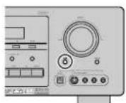
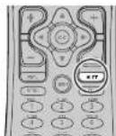
To temporarily silence all speaker outputs such as when interrupted by a phone call, press the MUTE button on the front panel or MUTE button on the remote.
This will interrupt the output to all speakers and the head-phone jack, but it will not affect any recording or dubbing that may be in progress.
When the system is muted, the display will show "MUTE".
Press the MUTE button again to return to normal operation.
USING THE SLEEP TIMER
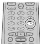
To program the SR8400 for automatic standby, press the SLEEP button on the remote. Each press of the button will increase the time before shut down in the following sequence.
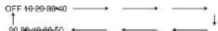
The sleep time will be shown for a few seconds in the display on the front panel, and it will count down until the time has elapsed.
When the programmed sleep time has elapsed, the unit will automatically turn off.
Note that the SLEEP indicator on the display will illuminate when the Sleep function is programmed. To cancel the Sleep function, press the SLEEP button until the display shows "SLEEP OFF" and the SLEEP indicator will disappear.
NIGHT MODE
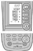
To select the NIGHT mode, prose the AMP button and press the > button until PAGE3 is displayed. Press the NIGHT (D1) button.
Selecting the Night Mode ON is effective in Dolby Digital only, and it compresses the dynamic range. This softens loud passages such as sudden explosions, to help prevent disturbing others late at night.
To turn off the Nlight mode, press the NIGHT button again.
SURROUND MODE
The SR8400 is equipped with many surround modes. These are provided to reproduce a variety of surround sound effects, according to the content of the source to be played.
The available surround modes may be restricted depending on the input signal and speaker setup.
AUTO
When this mode is selected, the receiver determines whether the digital input signal is Dolby Digital, Dolby Digital Surround EX, DTS, DTS-ES, DTS 96/24 or PCM-audio.
Surround EX & DTS-ES will operate for multichannel source that has a Dolby Digital Surround EX or DTS-ES auto trigger flag in the digital signal.
When a Dolby Digital or DTS signal is input, the number of channels for which the corresponding signal is encoded will be played.
Inputting a Dolby Digital two channel signal with Dolby surround status automatically subjects that signal to Pro Logic Ix movie processing before play.
PCM 96 kHz source material can be played in this mode.
HDCD source material can be played in this mode.
-
When you use this mode with certain DVD and CD players, performing operations such as "Skip" or "Stop" may momentarily interrupt the output.
-
When the signal is not decoded, the mode is changed to AUTO mode automatically. Refer to page 22 to confirm the available decoding mode.
DO MODE
(Dolby Digital, Pro Logic IIx MOVIE, Pro Logic IIx MUSIC, Pro Logic IIx GAME Pro Logic)
This mode is used with source materials encoded in Dolby Digital and Dolby Surround.
DOLBY DIGITAL
This mode is enabled when playing source materials encoded in Dolby Digital.
Playing multichannel encoded 6.1 or 7.1-channel Dolby Digital sources provides five main audio channels (left, center, right, surround left and surround right) and Low Frequency Effect channel. Dolby Digital EX decoding is not available in this mode.
Dolby Pro Logic Ix brings the excitement of surround sound to any stereo mix, while making existing Dolby Surround mixes sound more like discrete 5.1 channels Surround sound.
Dolby Pro Logic IIx has 3 modes. Please see below. Pro Logic IIx MOVIE
This mode provides 6.1 or 7.1 channel surround sound from Dolby Surround encoded stereo movie sound tracks.
Pro Logic IIx MUSIC
This mode provides 6.1 or 7.1 channel surround sound from conventional stereo sources, analog or digital, such as CD, Tape, FM, TV, Stereo VCR, etc.
Pro Logic IIx GAME
Game mode restores the impact low-frequency surround effects by routing them to the system's subwoofer.
Pro Logic
This mode emulated original Dolby Pro Logic decoding (3:1 surround) suit for Dolby Surround encoded stereo movie soundtracks.
Notes:
- Pro Logic IIx mode will decode as Pro Logic II mode when the SURROUND BACK SPEAKER is set NONE in SPEAKER SETUP menu. (See SPEAKER SETUP, page 18)
- Pro Logic IIx mode is available for a 2ch input signal which is encoded in Dolby Digital or PCM format.
PCM audio signals can be subjected to Pro Logic processing when the sampling frequency is 32 kHz, 44.1 kHz or 48 kHz.
EX:ES
This mode provides 6.1 channel surround for DOLBY DIGITAL EX, DTS-ES encoded source material such as DVD.
This mode cannot be used when an analog input has been selected.
Dolby Digital EX
In a movie theater, film soundtracks that have been encoded with Dolby Digital surround EX technology are able to reproduce an extra channel which has been added during the mixing of the program.
This channel, called Surround Back, places sounds behind the listener in addition to the currently available front left, front center, front right, surround right, surround left and subwoofer channels.
This additional channel provides the opportunity for more detailed imaging behind the listener and brings more depth, spacious ambience and sound localization than ever before.
Dolby Digital EX is not available in the system without surround back speaker(s).
DTS-ES (Discrete 6.1, Matrix 6.1)
DTS ES adds the surround center channel audio to the DTS 5.1-channel format to improve the acoustic positioning and makes acoustic image movement more natural with the 6.1-channel reproduction.
This receiver incorporates a DTS-ES decoder, which can handle DTS-ES Discrete-encoded and DTS-ES Matrix encoded program sources from DVD, etc..
DTS-ES Discrete 6.1 features digital discrete recording of all channels including the surround back channel(s) and higher quality of audio reproduction. DTS-ES is not available in the system without a surround back speaker.
dtsmODE
(dts, Neo:6 Cinema, Neo:6 Music)
This mode is for DTS encoded source materials such as LASER DISC, CD, and DVD. Neo:6 is for some 2 channel sources.
dts : This mode is enabled when playing source materials encoded in dts multichannel.
Playing multichannel encoded 5.1-channel dts sources provides five main audio channels (left, center, right, surround left and surround right) and Low Frequency Effect channel.
dts-ES decoding is not available in this mode.
The DTS mode cannot be used when an analog input has been selected.
Neo:6 Cinema, Neo:6 Music
This mode decodes 2-channel signals into 6-channel signals using high-accuracy digital matrix technology.
The DTS NEO:6 decoder has near-discrete properties in the frequency characteristics of the channels as well as in channel separation.
According to the signals to be played back, DTS NEO:6 uses either the NEO:6 CINEMA mode optimized for movie playback or the NEO:6 MUSIC mode optimized for music playback.
Note:
- Neo6 mode is available to 2ch input signals which are encoded in Dolby Digital or PCM format.
PCM audio signals can be subjected to Pro Logic processing when the sampling frequency is 32 kHz, 44.1 kHz or 48 kHz.
MULTICH.ST
This mode is used to create a wider, deeper and more natural soundstage from two channel source material. This is done by feeding the left channel signal to both left front and left surround speaker and the right channel signal to both right front and right surround speaker. Additionally, the center channel reproduces a mix of the right and left channel.
CIRCLE SURROUND II (CSII-CINEMA, CSII-MUSIC, CSII-MONO)
Circle Surround is designed to enable multichannel surround sound playback of non-encoded and multichannel encoded material.
Backward compatibility provides listeners with up to 6.1 channels of surround performance from entire collection of music and film, including broadcast, videotape and stereo recorded music.
Depending on source material, you can select CSII-Cinema mode, CSII-Music mode or CSII-Mono mode.
Note:
- CS II mode is available for 2ch input signals which are encoded in Dolby Digital or PCM format.
PCM-audio signals can be subjected to Pro Logic processing when the sampling frequency is 32 kHz, 44.1 kHz or 48 kHz.
VIRTUAL
This mode creates a virtualized surround sound experience from a two-speaker (front L and R) playback system playing any multichannel audio source (such as found on DVDs and digital broadcasts), including Dolby Digital, Dolby Pro Logic or DTS.
STEREO
This mode bypasses all surround processing. In stereo program sources, the left and right channels play normally when PCM-audio or analog stereo is input.
With Dolby Digital and DTS sources, the 5.1 multichannels are converted to two channel stereo. 96kHz PCM source material can be played back in stereo mode.
HDCD source material can be played in this mode.
S (SOURCE) - DIRECT
In the source direct mode, the tone control circuit and bass management configuration are bypassed for full range frequency response and the purlist audio reproduction.
96 kHz PCM source material can be played back in this mode.
HDCD source material can be played in this mode.
Notes:
- Internal speaker size is setup to front L / R = Large, Center = Large, Surround L / R = Large and Subwoofer = Yes automatically. Tone controls and additional processing are also defeated.
- When you use this mode with certain DVD and CD players, performing operations such as "Skip" or "Stop" may momentarily interrupt the output.
CAUTION
NOTE for DTS signal
- Connected DVD player, laser-disc player or CD-player needs to support DTS-digital output. You may not be able to play some DTS source signals from certain CD players and LD players even if you connect the player to the SR8400 digitally. This is because the digital signal has been processed (such as the output level, sampling frequency, or frequency response) and the SR8400 cannot recognize the signal as DTS data.
Depending on the player used, DTS play may produce a short noise. This is not a malfunction.
While signals from DTS-laser disc or CD are playing in another Surround mode, you cannot switch to digital input or from digital input to analog input by INPUT SETUP in SETUP MAIN MENU or the A/D button.
The outputs for the VCR 1 OUT, DSS/VCR 2 OUT, TAPE OUT, and CD-R OUT output analog audio signals. Do not record from CDs or LDs that support DTS using these outputs. If you do, the DTS-encoded signal will be recorded as noise.
NOTE for Dolby Digital Surround EX signal
- When playing Dolby Digital Surround EX-encoded software in 6.1 channels, it is required to set the EX/ES mode.
Note that some of Dolby Digital Surround EX-encoded software does not contain the
identification signal. In this case, set the EX/ES mode manually.
NOTE for 96kHz PCM audio
- AUTO, Source-DIRECT, and STEREO modes can be used when playing PCM signals with a sampling frequency of 96kHz (such as from DVD-Video discs that contain 24 bit, 96kHz audio). If such signals are input during playback in one of the other surround modes, output from SRB400 will be muted.
Certain DVD player models inhibit digital output. For details, refer to the player's operation manual.
Some DVD formatted discs feature copy protection. When using such disc, 96 kHz PCM signal is not output from the DVD player. For details, refer to the player's operation manual.
NOTE for HDCD signal
- HDCD is effective only at the time of digital input.
^ 念 AUTO, Source-DIRECT, and STEREO modes can be used when playing HDCD signals (such as from CD discs that contain HDCD).
You may not be able to play some HDCD source signals from certain CD players if you connect the player to the SR8400 digitally.
This is because the digital signal has been processed (such as the output level, sampling frequency, or frequency response) and the SR8400 cannot recognize the signal as HDCD data.
The relation between the selected surround mode and the input signal
The surround mode is selected with the surround mode selector on SR8400 or the remote control unit. However, the sound you hear is subject to the relationship between the selected surround mode and input signal. That relationship is as follows;
| Surround Mode | Input Signal Decoding | Output Channel Front Information display | ||||||
| L/R C | SL SBL SR SBR | Sua | Signal format indicators Channel status | |||||
| AUTO Dolby Surf | EX Dolby Digital EX | O | O | O | O | OO DIGITAL L, C, R, SL, SR, S, LFE | ||
| Dolby D (5.1ch) Dolby Digital 5.1 | Digital 5.1 | O | O | O | - | OO DIGITAL L, C, R, SL, SR, LFE | ||
| Dolby D(2ch) Dolby Digit 2.0 | O | - | - | - | - | OO DIGITAL L R | ||
| Dolby D (2ch Sum) Pro Logic II x movie | O | O | O | O | - | OO DIGITAL , , , , , , , , , , , , , , , , , , , , , , , , , , , , , , , , , , , , , , , , , , , , , , , , , , , , , , , , , , , , , , , , , , , , , , , , , , , , , , , , , , , , , , , , , , , , , , , , , , , , | L, R, S | |
| DTS ES | DTS ES | O | O | O | O | Ods ES | ||
| DTS 36/24 | DTS 96/24 | O | O | O | - | Oss 96/24 | ||
| DTS (5.1ch) | DTS 5.1 | O | O | O | - | Ots | ||
| PCM (Audio) | PCM (Stereo) | O | - | - | - | PCM | ||
| PCM 96kHz PCM (96Hz Stereo) | O | - | - | - | - | PCM | ||
| HDCC | Stereo | O | - | - | - | POM, HDCD L, R | ||
| Analog | Stereo | O | - | - | - | ANALOG | ||
| S-DIRECT | Dolby D Sum: EX | Dolby Digital EX | O | O | O | O | OO DIGITAL L, C, R, SL, SR, S, LFE | |
| Dolby D (5.1ch) Dolby Digital 5.1 | Digital 5.1 | O | O | O | - | Oo Digital L, C, R, SL, SR, LFE | ||
| Dolby D (2ch) | Dolby Digital 2.0 | O | O | O | - | OO Digital L R | ||
| Dolby D (2ch Sum) Pro Logic II x movie | Logic II x movie | O | O | O | - | OO Digital , , , , , , , , , , , , , , , , , , , , , , , , , , , , , , , , , , , , , , , , , , , , , , , , , , , , , , , , , , , , , , , , , , , , , , , , , , , , , , , , , , , , , , , , , , , , , , , , , , , - | L, R, S | |
| DTS ES | DTS ES | O | O | O | O | Ods ES | ||
| DTS 36/24 | DTS 96/24 | O | O | O | - | Oss 96/24 | ||
| DTS (5.1ch) | DTS 5.1 | O | O | O | - | Ots ES | ||
| PCM (Audio) | PCM (Stereo) | O | - | - | - | PCM | ||
| PCM 96kHz PCM (96Hz Stereo) | O | - | - | - | - | PCM | ||
| HDCC | Stereo | O | - | - | - | POM, HDCD L, R | ||
| Analog | Stereo | O | - | - | ANALOG | |||
| EXES | Dolby D Sum: EX | Dolby Digital EX | O | O | O | O | OO DIGITAL L, C, R, SL, SR, S, LFE | |
| Dolby D (5.1ch) Dolby Digital 5.1 | Digital 5.1 | O | O | O | - | OO Digital L, C, R, SL, SR, LFE | ||
| DTS ES | DTS ES | O | O | O | O | Ods ES | ||
| DTS 36/24 | DTS 96/24 | O | O | O | - | Oss 96/24 | ||
| DTS (5.1ch) | DTS 5.1 | O | O | O | - | Ots ES | ||
| DTS (2ch) | Pro Logic II x | O | O | O | - | OO Digital L, R | ||
| Dolby D (2ch Sum) Pro Logic II x | Logic II x | O | O | O | - | OO Digital , , , , , , , , , , , , , , , , , , , , , , , , , , , , , , , , , , , , , , , , , , , , , , , , , , , , , , , , , , , , , , , , , , , , , , , , , , , , , , , , , , , , , , , , - | L, R, S | |
| PCM (Audio) | Pro Logic II x | O | O | O | O | PCM | ||
| Analog | Pro Logic II x | O | O | O | - | ANALOG | ||
| DTS (Nec & Cinema)(Nec & Music) | DTS ES | DTS 5.1 | O | O | O | - | Ots ES | |
| DTS 96/24 | DTS 96/24 | O | O | O | - | Ots 96/24 | ||
| DTS 15 Ch | DTS 5.1 | O | O | O | - | Ots | ||
| PCM (Audio) | Neo S | O | O | O | - | PCM | ||
| Analog | Neo S | O | O | O | - | ANALOG | ||
| Dolby D (2ch) | Neo S | O | O | O | - | OO Digital L R | ||
| Dolby D (2ch Sum) Neo S | Neo S | O | O | O | - | OO Digital L R | ||
| CS II CinemaCS II MusicCS II Mono | PCM (Audio) | CS II | O | O | O | - | PCM | |
| Analog | CS II | O | O | O | - | ANALOG | ||
| Dolby D (2ch) Dolby D (2ch) | CS II | O | O | O | - | OO Digital L R | ||
| Dolby D (2ch Sum CS)II | O | O | O | O | - | OO Digital L R SURROUND | ||
| STEREO | Dolby Sum: EX Stereo | O | - | - | - | OO DIGITAL L, C, R, SL, SR, S, LFE | ||
| Dolby D (5.1ch) Stereo | O | - | - | - | OO DIGITAL L, C, R, SL, SR, LFE | |||
| Dolby D (2ch) Stereo | O | - | - | - | OO DIGITAL L R | |||
| Dolby D (2ch Sum) Stereo | O | - | - | - | OO Digital L R SURROUND | |||
| DTS ES | Stereo | O | - | - | - | Ots ES | ||
| DTS 36/24 | Stereo | O | - | - | - | Ots 36/24 | ||
| DTS (5.1ch) | Stereo | O | - | - | - | Ots | ||
| PCM (Audio) | Stereo | O | - | - | - | PCM | ||
| PCM 96kHz | Stereo | O | - | - | - | PCM | ||
| HDCC | Stereo | O | - | - | - | POM, HDCD L, R | ||
| Analog | Stereo | O | - | - | - | ANALOG | ||
| Virtual | Dolby Sum: EX Virtual | O | - | - | - | OO DIGITAL L, C, R, SL, SR, S, LFE | ||
| Dolby D (5.1ch) Virtual | O | - | - | - | OO DIGITAL L, C, R, SL, SR, LFE | |||
| Dolby D (2ch) Virtual | O | - | - | - | OO Digital L R | |||
| Dolby D (2ch Sum) Virtual | O | - | - | - | OO Digital L R SURROUND | |||
| DTS ES | Virtual | O | - | - | - | dis ES | ||
| DTS 15 Ch | Virtual | O | - | - | - | dis | ||
| PCM (Audio) | Virtual | O | - | - | - | PCM | ||
| PCM (Audio) | Virtual | O | - | - | - | PCM | ||
| Analog | Virtual | O | - | - | - | ANALOG | ||
| Multi Ch.Stereo | Dolby Sum: EX Dolby Digital EX | O | O | O | - | OO DIGITAL L, C, R, SL, SR, S, LFE | ||
| Dolby D (5.1ch) Dolby Digital 5.1 | O | O | O | - | OO DIGITAL L, C, R, SL, SR, LFE | |||
| Dolby D (2ch) Multi Channel Stereo | O | O | O | - | OO Digital L R | |||
| Dolby D (2ch Sum) Multi Channel Stereo | O | O | O | - | OO Digital L R SURROUND | |||
| DTS ES | DTS ES | O | O | O | - | Ots ES | ||
| DTS 36/24 | DTS 36/24 | O | O | O | - | Ots 36/24 | ||
| PCM (Audio) | Multi Channel Stereo | |||||||
| Analog | Multi Channel Stereo | |||||||
Note:
-
Dolby Digital (2 ch: Lf/RT): signal with Dolby Surround flag Speakers are full set.
-
No sound outputs from the surround speaker, center speaker and subwoofer if the DVD disc has no surround data.
Abbreviations
L/R: Front speakers
C:Center speaker
SL/SR:Surround speakers
SBI/SBR:Surround Back speakers
SubW: Sub woofer speaker
OTHER FUNCTION
TV AUTO ON/OFF FUNCTION
This function allows the component connected to the TV-VIDEO in jack to control the power (ON/ OFF) to the SR8400.
AUTO POWER ON
- Be sure the TV auto mode is ENABLED. (Refer page 19: System Setup)
- Connect your TV TUNER (etc) to the TV-VIDEO in terminal. Be sure to connect the VIDEO input.
- Turn OFF the power to the TV TUNER and the SR8400.
- Turn ON the TV TUNER and tune in a receivable station.
- When the station is received, the SRB400 turns ON and TV is selected automatically.
AUTO POWER OFF
- In the above situation, turn the TV TUNER OFF or select a channel that does not contain any broadcast.
- The power to the SR8400 switches to STANDBY after approx. 5 minutes.
Notes:
- AUTO POWER OFF is canceled if the SR8400 is set to a source other than TV.
The function reactivates when TV is selected again. Some TV broadcasts may cause the TV AUTO FUNCTION to turn ON.
The S-Video terminal does not support "TV AUTO ON/OFF" function.
ATTENUATION TO ANALOG INPUT SIGNAL
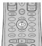
If the selected analog audio input signal is greater than the capable level of internal processing, the "PEAK" indicator will light up on the front display. If this happens, you should press the ATT button on the remote.
"ATT" indicator will be illuminated when this function is activated. The signal-input level is reduced by about half. Attenuation will not work with the output signal of TAPE-OUT, CD-R/MD-OUT, VCR1-OUT and DSS/VCR2-OUT.
This function is memorized for each individual Input source.
LISTENING THROUGH HEADPHONES
This jack may be used to listen to the SR8400's output through a pair of headphones. Be certain that the headphones have a standard 1:4" stereo phonoplug. (Note that the speakers will automatically be turned off when the headphone jack is in use.)
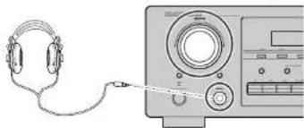
Notes:
- When using headphones, the surround mode will change to STEREO and TruSurround (TS) headphones by SURROUND MODE selector.
- The surround mode returns to the previous setting as soon as the plug is removed from the jack.
VIDEO ON/OFF
When no video signal is connected to the SRB400 or a DVD, etc., is connected directly to your TV, the unnecessary video circuit can be turned off by selecting the "VIDEO OFF" setting.
To select video off, press the AMP button and press the > button until PAGE4 is displayed. Press the V-OFF (D4) button.
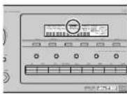
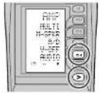
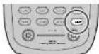
DISPLAY MODE
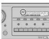
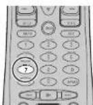
You can select the display mode for the front display of the SR8400.
To select this mode, press the DISP. on the remote control.
When this button is pressed, the display mode is switched in the following sequence.
Surround Mode Auto-display Off Display Off Input Function Surround Mode...
In Auto display off mode, the display is off. But, if you make a change to the unit such as input or surround mode, the display will show that change, then go back to off after about 3 seconds. When changing the volume, it is not displayed.
In Display off mode, the display is off completely. Notes:
Only the DISP indicator will be illuminated on the front display in display off condition
SELECTING ANALOG AUDIO INPUT OR DIGITAL AUDIO INPUT
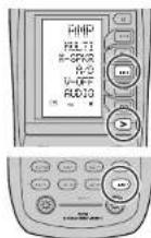
If you have already assigned the digital inputs, you can temporarily select the audio input mode for each input source as following procedures. Press the AMP button and press the > button until PAGE4 is displayed. Press the A/D (D3) button. When this button is pressed, the input mode is switched in the following sequence.
Digital Auto Digital Analog Digital Auto... In Digital Auto mode, the types of signals being input to the digital and analog input jacks for the selected input source are detected automatically. If no digital signal is being input, the analog input jacks are selected automatically.
In Digital mode, input is fixed to an assigned digital input terminal.
In analog mode, the analog input jacks are selected. This selecting is temporary, so the result will not be stored in memory.
If you need to change the input mode completely, use SYSTEM SETUP in OSD menu system. (see page 18)
RECORDING AN ANALOG SOURCE
In normal operation, the audio or video source selected for listening through the SR8400 is sent to the record outputs.
This means that any program you are watching or listening to may be recorded simply by placing machines connected to the outputs for TAPE OUT, CD-R/MD OUT, VCR1 OUT, and DSS/VCR2 OUT in the record mode.
To record the input source signal you are currently watching or listening to
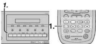
- Select the input source to record by pressing the corresponding Input selector button. The input source is now selected and you may watch or listen to it as desired.
- The currently selected input source signal is output to the TAPE OUT, CD-R/MD OUT, VCR1 OUT, and DSS/VCR2 OUT outputs for recording. 3. Start recording to the recording component as desired.
Recording the video from one source and the audio from another.
You can add the sound from one source to the video of another source to make your own video recordings.
Below is an example of recording the sound from a compact disc player connected to CD IN and the video from a video camera connected to AUX IN to video cassette recorder connected to the VCR1 OUT jack.
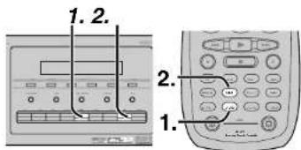
- Press the AUX1 input source button to set video output.
- Press the CD input source button to set audio output.
- Now "CD" has been selected as the audio input source and "AUX1" as the video input source.
Notes:
- If you change the input source during recording, you will record the signals from the newly selected input source.
- You cannot record the surround effects.
Digital input signals are only output to the digital outputs. There is no conversion from digital to analog.
When connecting CD players and other digital components, do not connect only the digital terminals, but the analog ones as well.
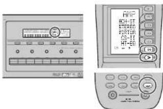
HT-EQ
Press the AMP button and press the > button until PAGE2 is displayed. Press the HT-EQ (DS) button to turn on the HT-EQ mode.
The tonal balance of a film soundtrack will be excessively bright and harsh when played back over audio equipment in the home. This is because film soundtracks were designed to be played back in large movie theater environments.
Activating the HT-EO feature when watching a film made for movie theaters corrects this and restores the correct tonal balance.
SPEAKER A/B
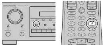
SR8400 has speaker system - A and speaker system-B for front L/R channels.
You can select these systems by pressing SPEAKERS A/B button on the front panel or SPK-AB on the remote
7.1 CH INPUT.
The SR8400 is equipped for future expansion through the use of Multi channel SACD multichannel player or DVD-Audio player.
When this is selected, the input signals connected to the L(front left), R (front right), CENTER, SL (surround left), SR (surround right), SBL (surround back left) and SBR (surround back right) channels of the 7.1 CH. In jacks are output directly to the front (left and right), center, surround (left and right) and surround back speaker systems as well as the pre-out jacks without passing through the surround circuitry.
In addition, the signal input to the SW (subwoofer) jack is output to the PRE OUT SW (subwoofer) jack.
The video input source is selected in the SETUP MAIN MENU to use this procedure. (Refer to 7.1 CH INPUT LEVEL, page 21)

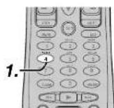
-
Press the 7.1 CH INPUT button on the front panel or press 7.1CH on the remote to switch the 7.1 channel input.
-
If it is necessary to adjust the output level of each channel, use "7.1 Ch. INPUT LEVEL" in the OSD menu system as desired. Adjust the speaker output levels so that you can hear the same sound level from each speaker at the listening position. For the front left, front right, center, surround left, surround right and surround back speakers, the output levels can be adjusted between -10 to +10dB . The subwoofer can be adjusted between -15 and +10dB .
These adjustments will be stored to 7.1 Ch. INPUT memory. (see to page 21) - Adjust the main volume with the MAIN VOLUME knob or the VOL buttons on the remote.
To cancel the 7.1 CH. INPUT setting, press the 7.1 CH INPUT button on the front panel or press 7.1 CH on the remote.
Notes:
- When the 7.1 Ch. Input is in use, you may not select a surround mode, as the external decoder determines processing.
In addition, there is no signal at the record outputs when the 7.1 Ch. Input is in use. - SRL and SBR of the speaker terminals are emitted no signal when the SURROUND BACK SPEAKER is set NONE in SPEAKER SETUP menu. (See SPEAKER SETUP, page 18)
AUX2 INPUT
If you don't need to connect 7.1 Ch. input terminals with multi channel decoder,
L(front left) and R (front right) inputs terminals are available as AUX2 Input.
In this case, You can connect additional audio source to AUX2 as other audio input terminals.
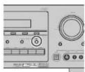
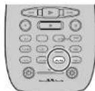
Frequency scan step for AM is selectable. Default setup is 10kHz step, if your country's standard is 9kHz step. Press TUNER button on the remote more than 6 seconds. Scan step will change.
Note:
- Preset memory for the tuner will clear by changing this setup.
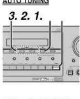
AUTO TUNING
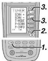
(Using the SR8400)
- To select tuner and desired band (FM or AM), press the TUNER button on the front panel.
- F/P button on the front panel to display the frequency.
- Press the TUNING button on the front panel for more than 1 second to start the Auto tuning function.
- Automatic searching begins then stops when a station is tuned in.
(Using the remote control unit)
- To select tuner and desired band (FM or AM), press the TUNER button twice within two seconds on the remote.
- Press the > button until PAGE2 is displayed.
- Press and hold the SCAN+ (D1) or SCAN-(D2) button for 1 second or more;
Automatic searching begins then stops when a station is tuned in.
If tuning does not stop at the desired station, use to the "Manual tuning" operation.
MANUAL TUNING
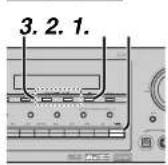
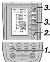
(Using the SR8400)
- To select tuner and desired band (FM or AM), press the TUNER button on the front panel
- Press the F/P (Frequency/Preset) button on front panel, to have the frequency appear on the display.
- Press the TUNING or buttons.
(Using the remote control unit)
To select tunes and desired band (FM or AM), press the TUNER button twice within two seconds on the remote.
2. Press the > button until PAGE2 is displayed 3. Press the SCAN+ (D1) or SCAN- (D2) button to tune in the deseired station.
DIRECT FREQUENCY CALL
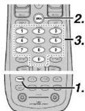
To select timer and desired band (FM or AM), press the TUNER button twice within two seconds on the remote.
2. Press the GUIDE on the remote, display will show "FREQ ----".
3. Input your desired station's frequency with the ten numbered keypad on the remote.
4. The desired station will automatically be tuned.
(FM) TUNING MODE (AUTO STEREO OR MONO)
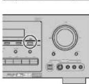
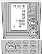
When in the auto stereo mode, AUTO Indicator will be illuminated on the display.
The "ST" indicator is illuminated when a stereo broadcast is tuned in.
At open frequencies, the noise is muted and the "TUNED" and "ST" indicators are not illuminated. If the signal is weak, it may be difficult to tune into the station in stereo. In such a case, press the MODE button on the front panel. Or press the TUNER button and press the the > button until PAGE1 is displayed. Press the T-MODE (D4) button.
"AUTO" indicator is not illuminated, if FM stereo broadcasts are received in monaural and the "ST" indicator is not illuminated.
To return to auto stereo mode, press the MODE button or press T-MODE button on the remote again. AUTO indicator is illuminated the display.
PRESET MEMORY
With this unit you can preset up to 50 FM/AM stations in any order.
For each station, you can memorize the frequency and reception mode if desired.
AUTO PRESET MEMORY
This function automatically scans the FM and AM band and enters all stations with proper signal strength into the memory.
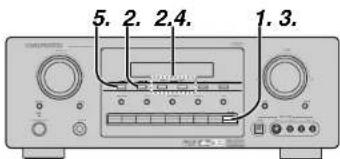
- To select FM, press the TUNER button on the front panel.
- While pressing the MEMORY button, press the TUNING button up.
"AUTO PRESET" will appear on the display, and scanning starts from the lowest frequency.
3. Each time the tuner finds a station, scanning will pause and the station will be played for five seconds.
During this time, the following operations are possible.
The band can be changed by the TUNER button. 4. If no button is pressed during this period, the current station is memorized in location Preset 02.
If you wish to skip the current station, press the TUNING button during this period, this station is skipped and auto presetting continues.
- Operation stops automatically when all 50 preset memory positions are filled or when auto scanning attains the highest end of all bands. If you desire to stop the auto preset memory at anytime, press the CLEAR button.
MANUAL PRESET MEMORY
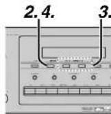
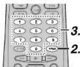
(Using the SR8400)
- Tune into the radio station you desire (Refer to the "MANUAL TUNING" or "AUTO TUNING" section).
- Press the MEMORY button on the front panel. (preset number) starts blinking on the display.
- Select the preset number by pressing the TUNING button, while this is still blinking (approx. 5 seconds)
- Press the MEMORY button again to enter. The display slows blinking.
The station is now stored in the specified preset memory location.
(Using the remote control unit)
Tune into the radio station you desire (Refer to the "MANUAL TUNING" or "AUTO TUNING" section).
2. Press the MEMO button on the remote. (preset number) starts blinking on the display.
3. Enter the desired preset number by pressing the numeric buttons.
Note:
- When entering a single digit number (2 or example), either input "0" or just input "2" and wait for a few seconds.
RECALLING A PRESET STATION
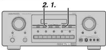
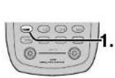
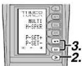
(Using the SR8400)
- Press the F/P button to show the preset station on the display.
- Select the desired preset station by pressing the TUNING buttons on the front panel.
(Using the remote control unit)
- Press the TUNER button twice within two seconds on the remote.
- Press the > button until PAGE4 is displayed
- Press the P-SET+ (D4) or P-SET-(D5) button to tune in the deseired preset station. Or enter the preset station number with the numeric buttons.
PRESET SCAN
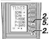
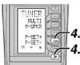
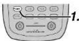
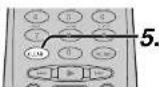
(Using the remote control unit)
- Press the TUNER button twice within two seconds on the remote.
- Press the > button until PAGE2 is displayed and press the P-SCAN (D4) on the remote. "PRESET SCAN" appears on the front display and then the preset station with the lowest preset number is recalled first.
- Preset stations are recalled in sequence (No.1 No.2 etc.) for 5 seconds each. No stored preset number will be skipped.
- You can fast forward the preset stations, press the > button until PAGE4 is displayed and press the P-SET+ (D4) continuously.
- When the desired preset station is received, cancel the preset scan operation by pressing the CLEAR button or P-SCAN (D4) on the remote.
CLEARING STORED PRESET STATIONS
You can remove preset stations from the memory using the following procedure.
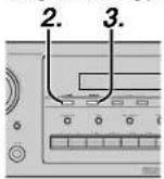
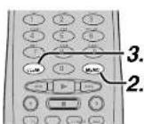
- Recall the preset number to be cleared with the method described in "Recalling," a preset station.
- Press the MEMORY button on the front panel or press the MEMO button on the remote.
-
The stored preset number blinks in the display for 5 seconds. While blinking, press the CLEAR button on the front panel or the remote.
-
"xx CLEAR" appears on the display to indicate that the specified preset number has been cleared.
Notes:
- To clear all stored preset stations, press and hold the CLEAR and the F/P buttons for two seconds.
SORTING PRESET STATIONS
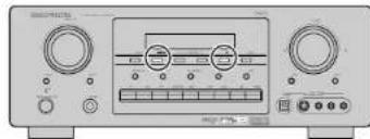
If you have stations memorized, and there is a gap in the sequential order:
the stations are stored as follows
(notice there is no stations programmed for pre sets for 4-9), you can have pre set 10 become pre set 5:
To sort the numbers, press and hold the MEMORY and the F/P buttons.
"PRESET SORT" will appear on the display and sorting will be done.
NAME INPUT OF THE PRESET STATION
This function allows the name of each preset channel to be entered using alphanumeric characters. Before name Inputting, you need to store preset stations with the preset memory operation.
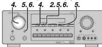
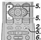
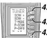
- Recall the preset number to be inputted name with the method described in "Recalling" a preset station.
- Press the MEMORY button on the front panel or press the MEMO button on the remote for more than 3 seconds.
- The left most column of the station name indicator flashes, indicating the character entry ready status.
- When the SELECT knob is turned, or press the > button until PAGE2 is displayed and press the SCAN+ (D1) or SCAN- (D2) on the remote, alphabetic and numeric characters will be displayed in the following order:
A→B→C...Z→1→2→3....0→-→+ →/→(Blank)→A
UP→
←DOWN
- After selecting the first character to be entered, press the MEMORY or ENTER buttons, press the MEMO button on the remote.
The entry in this column is fixed and the next column starts to flash. Fill the next column the same way.
To move back and forth between the characters, press the TUNING buttons. Or the CH+ or CH- on the remote.
Note:
- Unused columns should be filled by entering blanks.
- To save the name, press the MEMORY or the ENTER button, press the MEMO button on the remote for more than 2 seconds.
| Ten keypad | Press, press again, press again, etc. |
| 1 | A→E→C→1→A |
| 2 | D→E→F→2→D |
| 3 | G→H→I→3→G |
| 4 | J→K→L→4→J |
| 5 | M→N→O→5→M |
| 6 | P→Q→R→6→P |
| 7 | S→T→U→7→S |
| 8 | V→W→X→8→V |
| 9 | Y→Z→space→9→Y |
| 0 | -→+→i→0 |
MULTI ROOM SYSTEM
The Multi Room system is a function which allows you to listen to the same or a different source in a room other than the room in which the SR8400 is located.
To use this function, a multi room remote unit and remote control signal receiver available from your Marantz dealer are necessary.
The operations possible with the multi room function are explained briefly below.
For details, refer to the instruction manual supplied with the multi room remote control unit and receiver.
When the outputs of the MULTI ROOM OUT terminals are wired and connected to amplifiers installed in other rooms or MULTI SPEAKER OUT terminals are wired and connected to L&R speakers in other room, different sources can be played in rooms other than the main room In which this unit and the playback devices are installed.
SR8400 has some feature to MULTI ROOM SYSTEM as source selector, OSD Information, sleep timer, Multi Room Speaker output and remote control.
MULTI ROOM PLAYBACK USING THE MULTI ROOM OUT TERMINALS
The SR8400 is equipped with audio pre-out terminals for which the volume is adjustable and composite video output terminals as the MULTI ROOM output terminals.
A separately sold stereo power amplifier can be connected to enjoy multi room playback.
Operation to MULTI ROOM OUT without the remote controller.
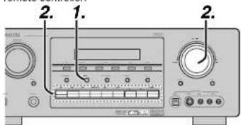
1. Press the MULTI ROOM button. The unit enters multi room mode and the display indicates "SELECT SOURCE" and flashes the "MULTI" indicator for approx. 10 seconds.
- In this time, you can select the input source by pressing the input selector buttons. Then, the display indicates "MULTI VOLUME" "MULTI VOL.xx" for approx. 5 seconds.
- During this time, you can set the volume level in the multi room as desired. This will only set the volume in the second room.
MULTI ROOM PLAYBACK USING THE MULTI SPEAKER TERMINALS
The SR8400 allows you to connect another set of speakers and place them in a different room or separated area for listening to music. Operation to MULTI ROOM SPEAKER without the remote controller.
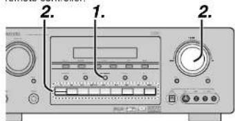
- Press the MULTI SPEAKER button. The unit enters multi room mode and the display indicates "SELECT SOURCE" and flashes the "MULTI" indicators for approx. 10 seconds.
- In this time, you can select the input source by pressing the input selector buttons.
-
Then, the display indicates "MSPKR VOLUME" "MSPKR VOL.-18" for approx. 5 seconds. During this time, you can set the volume level in the multi room as desired.
This will only set the volume in the multi room. Notes for MULTI ROOM SPEAKER -
MULTI ROOM SPEAKER On/Off is available in main room only.
- MULTI ROOM SPEAKER output terminals can be used when the SURROUND BACK SPEAKER is set NONE in SPEAKER SETUP menu. (See SPEAKER SETUP, page 18)
- "The Surr. Back Speakers are in use" is displayed by pressing the MULTISPEAKER button when the SURROUND BACK SPEAKER is set except NONE in SPEAKER SETUP menu. (See SPEAKER SETUP, page 18)
OPERATION OF THE MULTI ROOM OUTPUTS WITH THE REMOTE CONTROL FROM A SECOND ROOM.
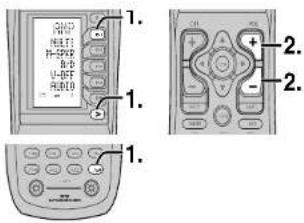
- Press MULTI on the multi room remote control from the MULTI ROOM.
(Press the AMP button and press the the > button until PAGE4 is displayed. Press the MULTI (D1) button.)
This operations will put the SR8400 into multi room mode and "MULTI" will be illuminated on the display.
MULTI ROOM Video output will show OSD information for the MULTI ROOM setup.
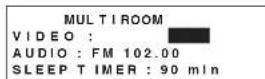
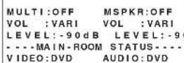
- Press the VOL + or VOL - button on the multi room remote control to set the desired volume.
- In multi room mode, the multi room remote control can be used in the multiroom to operate the following functions.
General:
Controlling volume level, sleep timer, and muting. Selecting input audio and video source
Tuner:
Selecting hand, controlling pre-set channel up and down, tuning up and down, direct frequency call.
Notes for the multi room system:
- The MULTI ROOM OUT has analog outputs.
This does not support digital input signals.
If the Tuner (FM or AM) is active in the main room, you can not control any function of the timer.
In this case, You must listen to the same satation as the main room.
- Press the desired function button.
The selected function name and USE are displayed in the LCD. - Press the desired operation buttons to play the selected component.
For details, refer to the component's user guide.
It may not be possible to operate some models.
CONTROLLING A MARANTZ DVD PLAYER (DVD MODE)
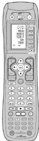
| SOURCE ON/OFF | Turns the DVD player on and off |
| POWER ON Turns the DVD player on | |
| POWER OFF Turns the DVD player off | |
| D1 - D5 / > (Page) | (Refer to page vi) |
| CursorOK Move the cursor, enters the setting | |
| MENU Calls up the menu of DVD disc | |
| 0-9 Input the number | |
| MEMO Call up the programming menu | |
| CLEAR Clears the resulting | |
| ▶ | Play |
| ←/→▶ | Skip forward or previous chapter track |
| ■ | Stop |
| || | Pause |
CONTROLLING A MARANTZ CD PLAYER (CD MODE)
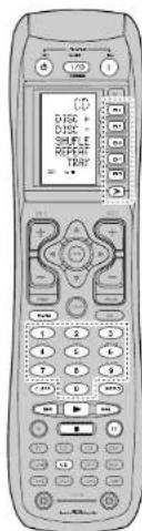
| SOURCE ON/OFF Turns the CD player on and off |
| POWER ON Turns the CD player on |
| POWER OFF Turns the CD player off |
| D1 - D5 / > (Page) (Refer to page vi) |
| MENU Switches the display information |
| 0-9 Input the numeric |
| MEMO Programs |
| CLEAR Clears the inputting |
| > Play |
| Skip forward or previous track |
| Stop |
| II Pause |
CONTROLLING A MARANTZ VCR (VCR MODE)
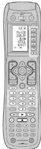
| SOURCE ON/OFF Turns the VCR on and off | |
| D1 - D5 >[Page] (Refer to page vi) | |
| MENU Call up the menu | |
| EXIT Ends the programming menu | |
| 0-3 Input the numeric | |
| Play | |
| Skip forward or previous track | |
| Stop | |
| Pause | |
| Record |
CONTROLLING A MARANTZ CD REORDER (CDR MODE)
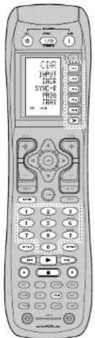
| SOURCE ON/OFF | Turns the CD recorder on and off |
| POWER ON | Turns the CD recorder on |
| POWER OFF | Turns the CD recorder off |
| D1 - D5 > (Page) | (Refer to page v) |
| MENU | Switches the display information |
| C-9 | Input the numeric |
| MEMO | Programs |
| CLEAR | Clears the inputting |
| ▲ | Play |
| ← | → | Skip forward or previous track |
| ■ | Stop |
| II | Pause |
| ● | Record |
CONTROLLING A MARANTZ MD DECK (MD MODE)
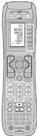
| SOURCE ON/OFF | Turns the MD deck on and off |
| POWER ON | Turns the MD deck on |
| POWER OFF | Turns the MD deck off |
| D1 ~ D5 / > (Page) | (Refer to page v0) |
| MENU | Switches the display information |
| 0~9 | Input the numeric |
| MEMO | Programs |
| CLEAR | Clears the inputing |
| ▶ | Play |
| ←/→ | Skip forward or previous track |
| ■ | Stop |
| II | Pause |
| ● | Record |
CONTROLLING A MARANTZ TAPE DECK (TAPE MODE)
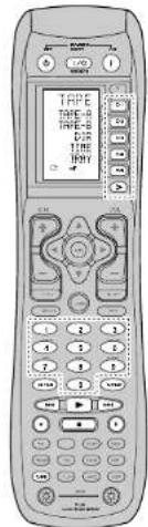
| SOURCE ON/OFF | Turns the TAPE deck on and off |
| POWER ON | Turns the TAPE deck on |
| POWER OFF | Turns the TAPE deck off |
| D1 - D5 ! > (Page) | (Refer to page v) |
| 0-9 | Input the numeric |
| MEMO | Programs |
| CLEAR | Clears the inputting |
| ▶ | Play |
| ← ↓ → | Skip forwards or previous track |
| ■ | Stop |
| II | Pause |
| ● | Record |
BASIC OPERATION
USE MODE
(Normal operation status)
This remote control is preset with a total of 12 types of remote codes, including Marantz TV (television), DVD, VCR (VCR deck), DSS (satellite broadcasting tuner), TUNER, CD, CD-R, MD, TAPE (tape deck), AUX1, AUX2, and AMP (amplifier).
Learning is not necessary for Marantz products. You can use these products without setting any codes.
1. Press the SOURCE button.
For this example, press DVD.
DVD is shown on the LCD, and the remote control is set for DVD.
Pressing the source button once changes the remote control to the settings for the source that was pressed.
To change the amplifier or other source, press the SOURCE button twice (double-click). The code is sent, and then the amplifier source changes to DVD.
- Press the buttons to operate the DVD.
The indicator is shown on the LCD while the
remote control codes are being transmitted. It is not displayed when buttons without stored code are pressed.
- The direct buttons can be used to perform up to 20 operations for each of the 12 sources, including DVD, TV, AMP, and other AV equipment.
The buttons consist of the D1 to D5 buttons, and the equipment is operated by pressing the buttons corresponding to the indicators on the LCD.
Four pages are available, and press the > button to select a page. The current page position is displayed on the LCD.
PRESET MODE
(When operating non-Marantz AV equipment products)
This remote control is preset with remote control codes from AV equipment by other manufacturers. The preset codes are TV, VCR, LD, CABLE, DSS, DVD, TAPE, TUNER, CD, CD-R, MD and AMP. Settings can be made in one of two ways.
When the preset codes are set, the following codes are contained in the source button of the remote control.
See the attached manufacturer number list for the preset manufacturers, devices, preset numbers, and other settings.
| Remote control Correspondng Device source name preseal code | name | |
| TV TV Television | ||
| DVD DVD DVD player | ||
| VCR VCR Video port | ||
| DSS SATELLITE | Satellite broadcasting | tuner equipment |
| TUNER | RECEIVER/TUNER | AM FM TUNER |
| CD/CD/CD-R PL ayER CD player | ||
| CD-R/CD/CD-R PL ayER CD recorder | ||
| MD/CD/CD-R PL ayER MD deck | ||
| TAPE TAPE | Cassette rack | |
| AUX1 CABLE | Cable television | |
| AUX2 LASER DISC | Laser disc player | |
| AMP | AMPLIFIER Amplifier or receiver | |
| RECEIVER/TUNER | ||
- When using Marantz products, TV and DVD can be set to TV1 (TV:VDP: Projector) and TV2 (PDP: Plasma display), and DVD1 (first DVD player) and DVD2 (second DVD player), respectively, to match the customer's operating environment. These settings are made in PRESET mode.
In the factory default state, the remote control is set to TV1 and DVD1. To make the preset, enter the numbers below while referring to the section "Entering and Setting the Manufacturer Number Directly".
Entering and Setting the Manufacturer Number Directly
Refer to the manufacturer number list. This example shows how to set a SAMSUNG DVD player.
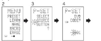
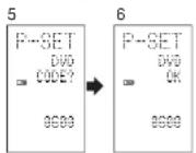
-
View the supplied manufacturer number list, and find the number of the manufacturer for the device that you are using.
-
Hold down the M button for three seconds or more.
The menu is displayed.
- Press the D1 (PRESET) direct button.
The Preset setting (P-SET) is displayed.
-
Press the DVD source button.
-
Press the numeric buttons to enter the four-digit manufacturer number.
Example: To enter "0600" from the manufacturer number list.
To correct the entered number, use the or cursor button to enter the correct number.
-
If no button is pressed for over one minute during the setting process, any settings that were made are cancelled.
-
Press the OK cursor button
-
Confirm the OK is displayed and then the display returns to the Preset Setting (P-SET). When the manufacturer number is entered correctly, OK is displayed momentarily on the STEEL.
-
If you enter a number not in the manufacturer number list, WRONG CODE is displayed, and then you return to the preset setting again
Check the manufacturer number list, and either set a different number or use the sequence function to set.
- To set the manufacturer number for another source device, repeat the procedure in steps 4 to 6.
- After the settings are completed, press the M button.
- Press the buttons on the remote control to check that the DVD can be operated correctly.
Setting Equipment Not Appearing in Manufacturer Number List
Use the sequence function to set equipment not appearing in the manufacturer number list. You may still be unable to set some equipment even when using the sequence function. In this case, the remote control can be programmed with codes individually.
In the sequence function, the power ON/OFF codes are transmitted by pressing the remote control buttons in order.
If the power for the equipment is left on, hold down the button until the equipment is turned off, and then release. This completes the setting.
This example shows how to set a DVD player.
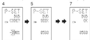
- Turn on the power of the DVD player.
- Hold down the M button for three seconds or more.
The menu is displayed. - Press the D1 (PRESET) direct button.
The Preset setting (P-SET) is displayed. - Press the DVD source button
- Hold down the CH+ or CH- button for one second or more.
- Press the CH+ button repeatedly in the interval for one second.
The signal is transmitted, and the display cycles through the code number.
Press the CII- button to go back to a number screen.
- Release the button once the DVD player turns off.
- Press the OK cursor button.
- Confirm the OK is displayed and then the display returns to the Preset Setting (P-SET).
- To set the manufacturer number for another source device, repeat the procedure in steps 4 to 8.
- After the settings are completed, press the M button.
- Press the buttons on the remote control to check that the DVD can be operated correctly.
Check the following points if the equipment which was set does not operate properly.
- If there is more than one number in the manufacturer number list, try setting a different number.
- There may be some buttons which cannot be used. Program the codes to the required buttons.
LEARN MODE
Programming the (PLAY) and Other Control Buttons and Numeric Buttons
This remote control is capable of learning and storing codes used by other remote controls that you already own.
For codes which are not learned, the remote control will transmit either the Marantz preset codes from the initial settings, or remote codes from another manufacturer's AV equipment which is set by the customer.
The receiver sensor for the remote control signals is located at the top of the remote control.
This example shows how to learn the codes from the remote control of a DVD player.
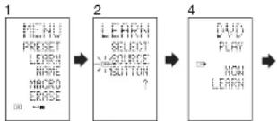
6 (When OK) (failed) (codes are full)
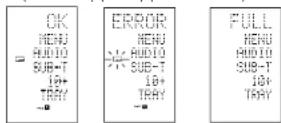
- Hold down the M button for three seconds or more. The menu is displayed.
- Press the D2 (LEARN) direct button. The LEARN setting (LEARN) is displayed. The indicator then blinks.
- Press the DVD source button.
- Press the PLAY button. The indicator blinks, and then displays to indicate that learning is ready.
- Place the receiver sensor of the remote control (top) so that it is facing the transmitter of the DVD remote control (top) at a distance of about 5 cm (2 inches).
- Press and hold down the (PLAY) button of the transmitting DVD remote control, and check that OK is displayed on the LCD. The remote control has finished learning when OK is displayed on the LCD.
If ERROR is displayed on the LCD, some error has prevented the command from being learned. If this happens, repeat the procedure for steps 4 and 5. In some rare cases, ERROR may be displayed repeatedly during the learning operation. In this case, the transmitting remote control may have special signal codes. These codes cannot be learned by this remote control.
- Follow the same procedure to make the remote control learn the other buttons.
- Repeat the procedure in steps 3 to 6 to have the remote control learn the signal codes from a TV, CD player, or other AV equipment.
- When no buttons are pressed for approximately one minute during the learning operation, the remote control automatically returns to USE mode.
- When programming the source buttons, switch to the source in step 3, and then press the source button again.
- When you have finished programming the codes for each button, press the M button. The use indicator is displayed on the LCD, and the newly stored codes can be used.
- If FULL is displayed on the LCD, the memory cannot hold any more learned codes in LEARN mode.
If FULL is displayed no matter how many times you try the learning operation, the remote control cannot accept any more new codes until some of the previously learned codes are deleted from the memory. Delete some of the learned buttons from the sources.
Note:
To learn the remote control code, a button of the transmitting remote control should be pressed and held down until the "OK" is displayed on the LCD of the RC1400.
The holding time needs for 5 seconds or more. This time is depend on the remote control code.
The M button and > button cannot be taught. Only each one code can be learned for the LIGHT buttons 1 and 2, regardless of the source.
Programming the Direct Buttons and Rewriting Names
This example shows how to program codes from other manufacturer products to the DVD MENU button (D1) and change the display to OSD.
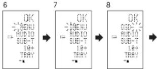
- Hold down the M button for three seconds or more.
The menu is displayed. - Press the D2 (LEARN) direct button. The LEARN setting (LEARN) indicator is displayed. The LDR indicator then blinks,
- Press the DVD source button.
The first page of the direct button screen is displayed. There are four available pages. Pressing the > buttons cycles through the pages in this order 1 2 3 4 1 - Press the D1 (MENU) direct button.
The indicator blinks, and then displays to indicate that learning is ready. - Place the receiver sensor of the remote control (top) so that it is facing the transmitter of the DVD remote control (top) at a distance of about 5cm (2 inches).
- Press and hold down the OSD button of the transmitting DVD remote control, and check that OK is displayed on the LCD.
The remote control has finished learning when OK is displayed on the LCD.
If EERROR is displayed on the LCD, some error has prevented the command from being learned. If this happens, repeat the procedure for steps 4 and 5.
After learning is completed, the remote control automatically switches to name rewriting mode. The left end : indicator on the MENU blinks to indicate that the blinking part can be rewritten. - If no names will be rewritten, press the OK cursor button. The display returns to learning standby mode by pressing the OK cursor button.
- To change the name, press the numeric buttonsto enter the text.
- Use the cursor buttons to move to the sections to be rewritten on the LCD.
To change MENU to OSD, press the 5 numeric button.
Each time the button is pressed, the display cycles through M N 0 5 M .
- After rewriting of the text is completed, press the OK cursor button.
To delete text that is already entered, press the 0 button to insert a space.
- In this example, MENU is changed to "OSD (space) (space)" in this step, and then OSD is displayed in the right side by pressing the OK button.
For details, refer to the section "Rewriting Names".
-
In the same way, use the > button to select the page, and then press the direct button to program the codes.
-
After programming the codes for each of the buttons, press the M button.
The [USE] indicator displays on the LCD, and the newly stored codes can be transmitted.
REWRITING NAMES
This remote control allows the rewriting of names for the sources and direct buttons. This operation is performed for each individual source. This example shows how to change the source name from DVD to AVD and AUDIO to SOUND.
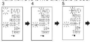
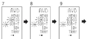
- Hold down the M button for three seconds or more.
The menu is displayed.
-
Press the D3 (NAME) direct button
-
Press the DVD source button. The indicator blinks. The blinks to indicate that the letter can be changed.
-
Press the cursor button twice. The D in DVD blinks to indicate that the letter can be changed.
-
Press the 1 numeric button to select A. Each time the numeric buttons are pressed, the button cycles through the alphanumeric characters shown below.
1: A → B → C → I → A
2: D → E → F → 2 → D
3: C → D → E → F → G
3:G→H→I→S→O
4:J→K→L→4→J
5:M→N→O→S→M
6:R→O→B→C
0.1→Q→K→0→1
7: S → T → U → 7 → S
8:V→W→X→8→V
9:Y→Z→/→9→Y
0:SPACE()→+→→→<→>→
0→SPACE(C)
- Press the cursor button.
The letter is changed to "A".
The and cursor buttons can be used to move the blinking indicator of the section to be rewritten.
-
Press the Cursor buttons to select AUDIO on the direct button indicator. The A flashes to indicate that the name can be changed.
-
Press the 7 numeric button to select S. Each time the button is pressed, the button cycles through S → T → U → 7 → S.
-
Press the cursor button to move the flashing section.
-
Press the 5 numeric button to select O.
-
Follow the same procedure to enter U, N, and D.
-
When finished entering the text, press the OK cursor button.
-
Press the M button
The use indicator displays on the LCD, and the newly stored codes can be used.
The input is overwritten, and so the currently displayed text is crased.
Up to six characters can be entered for the direct button indicator.
ERASING PROGRAMMED CODES (RETURNING TO INITIAL SETTINGS)
Codes can be erased in five ways: by buttons, direct buttons, direct button pages, sources, and by all memory contents.
Erasing Buttons and Erasing Direct Buttons
This example shows how to erase the code learned from the PLAY button of the DVD player and the AUTO code of the AMP direct button.
Erasing buttons
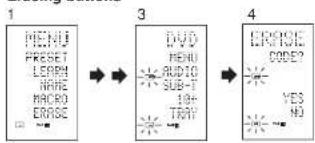
- Hold down the M button for three seconds or more.
The menu is displayed.
-
Press the D5 (ERASE) direct button.
-
Press the DVD source button.
The USE and LEAF indicators blink
-
Press the button PLAY that you want to erase while holding down the CLEAR button A message is displayed on the LCD.
-
Press the D4 (YES) direct button to erase. The code programmed to the PLAY button is erased.
When the code is cleared, the code for this button resets in the factory default code or becomes blank. To cancel the erasing operation, press the D5 (NO) button to return to the previous display.
To erase codes programmed for the CLEAR button, simply press the CLEAR button twice.
To erase codes programmed for the SOURCE button, simply press the SOURCE button twice.
Erasing direct buttons
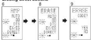
- Press the AMP source button
- Press the > button to display the first page for AMP.
- Press the D1 (AUTO) direct button to be erased while holding down the CLEAR button
- Press the D4 (YES) direct button to erase. The code programmed to the AUTO button is erased.
When the code is cleared, the code for this button resets to the factory default code or becomes blank. The rewritten name returns to the original name.
To cancel the erasing operation, press the D5 (NO) button to return to the previous screen. - When the erasing operation is finished, press the M button.
The [use] indicator displays to indicate that the remote control can now be operated.
Erasing Direct Button Pages
This example shows how to erase the entire direct button second page learned from the DVD player.
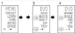
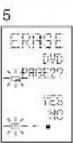
- Hold down the M button for three seconds or more.
The menu is displayed. - Press the D5 (ERASE) direct button
- Press the DVD source button.
The use and indicators blink. - Press the > button to display the second page.
- Press the > button while holding down the CLEAR button.
- Press the D4 (YES) direct button to erase.
All codes and names programmed in page 2 are erased. When the codes are cleared, the codes for this button reset to the factory default code or become blank. Any rewritten names return to the original name.
To cancel the erasing operation, press the D5 (NO) button to return to the previous screen.
- When the erasing operation is finished, press the M button.
The indicator lights up to indicate that the remote control can now be operated.
Erasing Sources
This procedure clears all codes and names programmed to the DVD, TV, or other sources. All codes and names in the four direct button pages are also erased.
This example shows how to erase the names and codes learned from the DVD player.
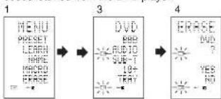
- Hold down the M button for three seconds or more.
The menu is displayed. - Press the D5 (ERASE) direct button
- Press the DVD source button
TheUSEandLEAH indicators blink - Press the DVD source button while holding down the CLEAR button.
-
Press the D4 (YES) direct button to erase. All codes and names programmed to the DVD source are erased. When the codes are cleared, the codes for this button reset to the factory default code or become blank. Any rewritten names return to the original name.
To cancel the erasing operation, press the D5 (NO) button to return to the previous display. -
When the erasing operation is finished, press the M button.
The [354] indicator displays to indicate that the remote control can now be operated.
Erasing All
This procedure clears (retsets) all programmed codes and names. Once all the data is cleared, the memory is returned to the factory default status. The programmed macros are also erased.
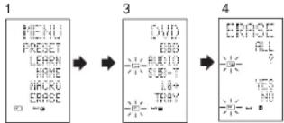
- Hold down the M button for three seconds or more.
The menu is displayed. 2. Press the D5 (ERASE) direct button The [use] and [use] indicators blink - Press the CLEAR button while holding down the POWER ON and OFF buttons at the same time.
- Press the D4 (YES) direct button to erase. All programmed codes and names are erased and reset to the factory default settings.
- To cancel the erasing operation, press the D5 (NO) button to return to the previous screen.
- To erase all operation takes a few seconds after the D4
button is pressed.
PROGRAMMING MACROS
This remote control can program a series of button operations in sequence.
Macros are a function that makes it possible to use a single button operation to perform a complex series of button operations any number of times. A single button can be programmed to perform up to 20 steps in sequence. A total of 20 buttons can be programmed with macros.
- For example, the following sequence of operations can be programmed to a macro. Switch amplifier to DVD source Set amplifier mode to AUTO Play DVD player Switch TV to video input
The factory default for the transmission interval (time) between macro operations is one second, but these signal transmission intervals can be set between approximately 0.5 seconds and 5 seconds in the Setup mode. Each transmission interval can be adjusted independently when programming or revising a macro.
Note:
If the signal transmission interval (interval time) is changed using the Setup mode (described later), this transmission interval is applied to all macro programs. To change individual signal transmission intervals, use the procedures in this section for programming macros and revising macros.
- No signals are transmitted while programming a macro.
- The M button, > button, cursor buttons. MEMO button, CLEAR button, and VOL buttons cannot be programmed.
- If no button is pressed for approximately one minute during programming, the remote control returns to the state before macro mode. In this case, the macro program is not stored.
- When executing macro mode, performing the source switching operation two or more times only changes the remote control mode and does not transmit any signals. (Switching of the source selector of the amplifier is valid only once.)
PROGRAMMINGMACROS
This example shows how to program a macro to the M-01 button.
(The screens shown in the example are the default factory states. If the names of direct buttons were rewritten, these modified names would be displayed.)
Switch amplifier to DVD source Play DVD player Set the interval to 2 seconds until the next signal is sent Switch TV to video Input Set the amplifier mode to AUTO
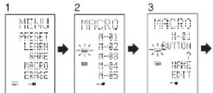
- Hold down the M button for three seconds or more. The menu is displayed.
- Press the D4 (MACRO) direct button. The macro menu is displayed.
- Press the D1 (M-01) direct button.
The menu has four pages, and so use the > button to select the page when programming other buttons.
- Press the buttons in the sequence that you want the operations performed. The actual program starts here. Each time a button is pressed, the name of the button is displayed on the LCD.
4-14243
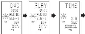
-
Press the DVD source button.
4.2.Press the▶PLAY) button
4-3. Press the Cursor buttons. The interval time is displayed on the LCD.
4-4. Press the Cursor buttons and set to 2.0 (seconds). -
Use the Cursor button to increase the time and the button to decrease the time. The interval time can be set from 0.5 seconds to 5 seconds.
-
To stop the time adjustment, press the D5 (CANCEL) direct button.
-
Press the OK cursor button.
4-6. Press the TV source button
4-7. Press the > button to display the first page.
4-8. Press the D1 (INPUT) direct button.
4-9. Press the AMP source button
4-10. Press the > button to display the first page.
4.11. Press the D1 (AUTO) direct button.
4-12. Press the OK cursor button. The LCD displays END to indicate that programming is completed.
5. To program another macro, repeat the procedure in steps 3 to 4-12.
6. To exit macro programming, press the M button.
The [Use] indicator displays to indicate that the remote control can now be operated.
When the macro are programmed 20 operations or more, the display returns macro menu.
Edit the macro so that it has 20 operations or less.
EXECUTING MACRO PROGRAMS
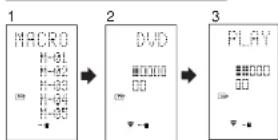
- Press the M button shortly. The menu is displayed.
- Press the D1 (M-01) direct button
-
Check that the operations of the program are executed step by step.
The name of the operation button is displayed on the LCD. -
The programmed section is indicated by . The bar indicator moves to indicate the progress of the program.
Select DVD source PLAY transmit Interval time: 2 seconds Select TV TV INPUT transmit Select AMP AUTO transmit End
- To cancel transmission of the program while it is in progress, press any button.
CHANGING NAMES OF MACRO PROGRAMS
Under the factory default settings, the names of the macro programs are set from M-01 to M-20, but you can change them to any desired name.
The text can have up to six characters, and it is entered using the numeric buttons.
This example shows how to change the M-01 name to MOVIE.
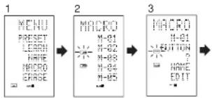
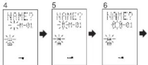
- Hold down the M button for three seconds or more.
- Press the D4 (MACRO) direct button. The macro menu is displayed. The macro icon displays and link
- Press the D1 (M-01) direct button. The NAME is displayed.
- Press the D3 (NAME) direct button. The "..." blinks to indicate that rewriting is possible.
- Press the 5 numeric button to select M.
- Press the >cursor button to next.
The "..." blinks to indicate that rewriting is possible. - Press the 5 numeric button to select O.
- Repeat steps 6 and 7, and then enter V, I, E and " (space").
To make changes In the text while entering it, use the or Cursor buttons to move to the blinking section. - After making the changes, press the OK cursor button. To change the names of other macro programs, repeat the procedure in steps 3 to 9.
10.To exit,press the M button.
ERASING STEPS OF MACRO PROGRAMS
This example shows how to delete the TV and INPUT steps from the following macro programmed to M-01.
The program is changed from
DVD PLAY TIME TV INPUT AMP AUTO
DVD PLAY TIME AMP AUTO.
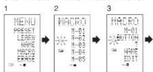
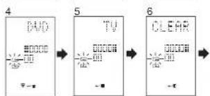
- Hold down the M button for three seconds or more.
The menu is displayed. - Press the D4 (MACRO) direct button. The macro menu is displayed.
The indicator displays and ENM blinks. - Press the D1 (M-01) direct button.
- Press the D5 (EDIT) direct button. The LCD displays DVD, and the step position is indicated by
The programmed section is indicated by - Press the cursor button to display TV.
- Press the CLEAR button: The LCD displays CLEAR, and TV and INPUT are deleted. When deleting steps from a macro program, the operations performed for a source after switching to the source are also deleted.
If the CLEAR button is pressed at the INPUT position, only the INPUT step is deleted.
The indicator for the step is also changed.
To check the modified steps, press the or cursor button.
7.To exit,press the M button When finished,to change another macro program, press the OK cursor button to return to the menu, and then repeat the procedure for steps 3 to 6.
OVERWRITING STEPS IN MACRO PROGRAMS
This example shows how to change the macro programmed to M-01 from DVD→PLAY→AMP→AUTO
DVD→PLAY→AMP→AUTCH
DVD PLAY TV INPUT
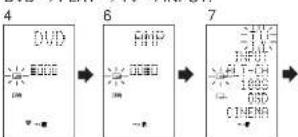
- Hold down the M button for three seconds or more.
- Press the D4 (MACRO) direct button. The macro menu is displayed. The indicator displays and blink
-
Press the D1 (M-01) direct button
-
Press the D5 (EDIT) direct button. The LCD displays DVD, and the step position is indicated by ■
The programmed section is indicated by. 5. Press the cursor button so that AMP is displayed. - Press the TV source button.
TV blinks for 0.5 seconds. - Press the D1 (INPUT) direct button. INPUT blinks for 0.5 seconds.
TV and INPUT are overwritten. - To check the modified steps, press the or cursor button.
- To exit, press the M button. When finished, to change another macro program, press the OK cursor button to return to the menu, and then repeat the procedure for steps 3 to 8.
INSERTING STEPS IN MACRO PROGRAMS
This example shows how to change the macro programmed to M-01 from
→PLAY→AMP→AUTO
DVD PLAY TV INPUT AMP AUTO
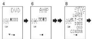
- Hold down the M button for three seconds or more.
The menu is displayed. - Press the D4 (MACRO) direct button. The macro menu is displayed.
The WER indicator displays and LEARN blinks. - Press the D1 (M-01) direct button
- Press the D5 (EDIT) direct button. The LCD displays DVD, and the step position is indicated by
The programmed section is indicated by - Press the cursor button so that AMP is displayed.
- Press the MEMO button
-
Press the TV source button, TV blinks for 0.5 seconds
-
Press the D1 (INPUT) direct button. INPUT blinks for 0.5 seconds. TV and INPUT are inserted.
- Press the OK cursor button. To check the modified steps, press the or>>cursor button.
10.To exit,press the M button. When finished,to change another macro program, press the OK cursor button to return to the menu, and then repeat the procedure for steps 3 to 9.
CLEARING MACRO PROGRAMS
When clearing macros, the macros programmed to the button are erased. Modified macro names are also returned to the factory default settings. This example shows how to clear a macro with the name MOVIE programmed to M-02.
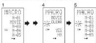
- Press the M button for three second or more. The macro menu is displayed.
- Press the D4 (MACRO) direct button. The macro menu is displayed.
- Press the D2 (MOVIE) direct button while holding down the CLEAR button.
- Press the D4 (YES) direct button to clear the macro. To cancel the clearing operation, press the NO (D5 button).
- To exit, press the M button. When finished, to change another macro program, press the OK cursor button to return to the menu, and then repeat the procedure for steps 2 to 4.
SETTING THE MACRO TIMER
Setting the macro timer enables the macro program to automatically turn the power for a device on or off or perform other operations.
In the settings, you can select to execute the macro timer everyday or only once.
Be sure to set the clock to the correct time before using the timer. The macro timer can only be set for one program a day.
This example shows how to use the timer only once at 20:35 to execute a macro programmed to M-01.
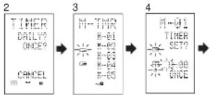
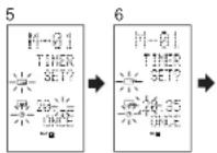
- Hold down the M button for three seconds or more.
The menu is displayed. - Press the > button to display the third page TIMER menu.
- Press the D2 (ONCE?) direct button. The M-TMR menu is displayed on the LCD.
To cancel timer operation, press CANCEL. - Press the D1 (M-01) direct button
The time which is set previously is displayed. - Press the 2 and 0 numeric button to set the hour Indicator to 20.
- Press the 3 and 5 numeric button to set the minute indicator to 35.
- Press the OK cursor button
This finalizes the time. - To exit, press the M button.
To cancel the macro timer, return to the TIMER menu and press the D5 (CANCEL) and then press D1 (M-01).
EXECUTING THE MACRO TIMER
The macro program starts when the time that was set is reached. The TIMER indicator lights up whenever the macro timer is activated.
Note:
To execute the macro timer, place the remote control facing the infrared sensor of the device to be operated. If the remote control is not in a suitable position, it may not operate the device properly.
CLONE MODE
CREATING COPIES USING CLONE MODE
All of the codes programmed to the RC1400 remote control can be copied to another RC1400 using a few simple operations.
-
The remote control can copy the entire contents or the contents for specific source buttons.
-
When copying the entire contents, all programmed codes, modified names, programmed macros, and signal transmission intervals are copied.
When copying the contents for source buttons, the programmed codes and modified names are copied.
Note:
The clone function can only be used for copying when using the same model (RC1400) for both the transmitting and receiving remote control.
COPYING ENTIRE CONTENTS
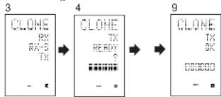
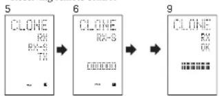
- Place the receiver sensor of the receiving remote control (top) so that it is facing the transmitter of the transmitting remote control (top) at a distance of about 5 cm (2 inches).
- Hold down the M button of the transmitting remote control for three seconds or more. The menu is displayed.
- Press the > button to display the fourth page CLONE menu.
- Press the D3 (TX) direct button. The transmitting side is now ready.
- Hold down the M button of the receiving remote control for three seconds or more. The menu is displayed.
- Press the × button to display the fourth page CLONE menu.
- Press the D1 (RX) direct button. The receiving side is now ready.
- Press the OK cursor button on the receiving remote control.
- Press the OK cursor button on the transmitting remote control. When copying is started, the bar indicates on both LCDs, up or down from the left to the right.
- When the copying operation is completed, TX OK is displayed on the LCD of the transmitting remote control, and RX OK is displayed on the LCD of the receiving remote control.
- Do not touch either of the remote controls during the copying operation. Doing so could cause copying to fail.
- If the copying fails in the middle of the copying process, RX ERROR is displayed on the receiving remote control. Check and perform steps 1 to 7 again.
- Copying takes about three minutes to complete when the transmitting remote control has been programmed to 100% capacity.
- Once copying is completed, press the M button on both remote controls.
COPYING BY SOURCE
The 12 sources can be copied on a source by source basis. You can select from up to 12 source types.
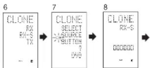
- Place the receiver sensor of the receiving remote control (top) so that it is facing the transmitter of the transmitting remote control (top) at a distance of about 5 cm (2 inches).
- Hold down the M button of the transmitting remote control for three seconds or more. The menu is displayed.
- Press the > button to display the fourth page CLONE menu.
- Press the D3 (TX) direct button.
The transmitting side is now ready. - Hold down the M button of the receiving remote control for three seconds or more.
- Press the × button to display the fourth page CLONE menu.
- Press the D2 (RX-S) direct button.
Press the source button to be copied.
The receiving side is now ready. The name of the source which was pressed is displayed on the LCD.
Each time the source button is pressed, the name is displayed on the LCD.
9. Press the OK cursor button on the receiving remote control.
10. Press the OK cursor button on the transmitting remote control.
When copying is started, the bar indicators on both LCDs start to move from the left to the right.
- When the copying operation is completed, TX OK is displayed on the LCD of the transmitting remote control, and RX OK is displayed on the LCD of the receiving remote control.
-
Do not touch either of the remote controls during the copying operation. Doing so could cause copying to fail.
-
If the copying fails in the middle of the copying process, ERROR is displayed on the remote control.
Check and perform steps 1 to 7 again.
- Once copying is completed, press the M button on both remote controls.
SETUP
SETTING THE LIGHTING TIME
-
The LCD lights up when the LIGHT buttons are pressed. The LCD remains lit while the pressed button is held down, and it goes off when the button is released.
-
The LCD continues to light up if another button is pressed while it is lit or if pressed within two seconds after the light goes off.
-
The lighting time can be set in one-second units from 0 to 60 seconds.
The LIGHT buttons have light-absorbing properties that enable them to store light. If the buttons are no longer illuminated in a dimly lit environment, bring the buttons near a fluorescent lamp or other light source for a sufficient amount of time. This should illuminate the buttons again.
- The LIGHT buttons consist of a LIGHT1 and LIGHT2 button, and they both perform the same operation.
The factory default lighting time is set to 15 seconds.
This example shows how to set the lighting time to 20 seconds.
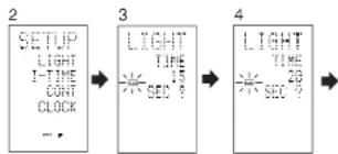
- Hold down the M button for three seconds or more.
The menu is displayed. - Press the > button to display the second page SETUP menu.
-
Press the D1 (LIGHT) direct button The LIGHT is displayed on the LCD
-
Press the Aor Cursor button to set the lighting time.
- Press the OK cursor button to enter the lighting time.
- Once the setting is finished, press the M button.
SETTING THE MACRO INTERVAL TIME
When a macro program is executed, control signals are transmitted in sequence. This transmission interval (interval time) can be set in 0.5-seconds units from 0.5 to 5 seconds. If the interval time is set in this Setup mode, the interval times for all programmed macros are changed. If necessary, use EDIT (see page 37) in the macro program to change the individual transmission times.
The factory default setting for the transmission interval is 1 second.
This example shows how to set the interval time to 5 seconds.
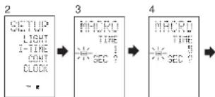
- Hold down the M button for three seconds or more.
The menu is displayed. - Press the > button to display the second page SETUP menu.
- Press the D2 (I-TIME) direct button
- Press the Cursor button to set the interval time.
Holding down the cursor button fast-forwards the time indicator. - Press the OK cursor button to enter the interval time.
- Once the setting is finished, press the M button.
ADJUSTING THE DISPLAY CONTRAST
The contrast of the LCD can be adjusted. Adjust for maximum visibility according to your viewing environment.
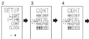
- Hold down the M button for three seconds or more.
The menu is displayed. - Press the > button to display the second page SETUP menu.
- Press the D3 (CONT) direct button
- Press the Cursor button and set the display contrast for maximum visibility. The adjustment has 10 levels.
The factory default setting for the contrast is the fifth level. - Press the OK cursor button to enter the display contrast.
- Once the setting is finished, press the M button.
TROUBLESHOOTING
In case of trouble, check the following before calling for service:
- Are the connections made properly?
- Are you operating the unit properly following the user's guide?
- Are the power amplifiers and speaker working properly?
If the unit does not operate properly, check items shown in the following table.
If your trouble cannot be recovered with the remedy actions listed in the following table, malfunction of the internal circuitry is suspected; immediately unplug the power cable and contact your dealer, nearest Marantz authorized dealer or the Marantz Service Center in your country.
| SYMPTOM | CAUSE | REMEDY |
| SR8400 cannot be turned up. | The power plug is not connected. | Connect the power plug to the outlet. |
| No sound and picture are output even when power is on. | Mute is on. | Cancel mute using the remote control unit. |
| The input cable is not connected correctly. | See the connection diagram and connect the cables correctly. | |
| The master volume control is turned all the way down. | Adjust the master volume. | |
| The function selector position is wrong. | Select correct position. | |
| No speaker output. | The headphones are connected to the headphones [ack. | Disconnect the headphones. (Speakers will not output sound when headphones are connected.) |
| Incorrect Audio or Video for selected source. | Input cable connected incorrectly. | Connect the cable correctly by referring to the connection diagram. |
| Incorrect Audio from a channel. | Speaker cable connected incorrectly. | Connect the cable correctly by referring to the connection diagram. |
| No Audio output from the center channel speaker. | The center speaker cable connection is incomplete. | Connect the cable correctly. |
| STEREO has been selected for Surround mode. | When STEREO is selected for Surround mode, no sound will be output from the center speaker. Set another Surround mode. | |
| Center = NONE has been selected in SETUP mode. | Make the correct setting. | |
| No Audio output from the surround speakers. | The surround speaker cable connection is incomplete. | Connect the cable correctly. |
| STEREO has been selected for Surround mode. | When STEREO has been selected for Surround mode, no sound will be output from the surround speaker. Set another Surround mode. | |
| Surround = NONE has been selected in SETUP mode. | Make the correct setting. | |
| No Audio output from the surround back speakers. | The surround back speaker cable connection is incomplete. | Connect the cable correctly. |
| Surround mode is not EX/ES mode. | Set surround mode EX/ES. | |
| Surround back = NONE has been selected in SPEAKERS SIZE SETUP | Make the correct setting. |
| SYMPTOM | CAUSE | REMEDY |
| Can not select EX/ES mode. | Surround center=NONE has been selected in SPEAKERS SIZE SETUP | Make the correct setting. |
| Input signal is incompatible. | Use 5.1 channel source. | |
| Can not select Pro Logic Tix mode. | Input signal is incompatible. | Use 2 channel Dolby Digital input signal, PCM input signal or analog input signal. |
| Can not select Neo6 mode. | Input signal is incompatible. | Use 2 channel Dolby Digital input signal, PCM input signal or analog input signal. |
| Can not select CSII mode. | Input signal is incompatible. | Use 2 channel Dolby Digital input signal, PCM input signal or analog input signal. |
| No output to Subwoofer Out. | Sub-woofer = NONE has been selected in SETUP mode. | Select Sub-woofer = YES. |
| Noise is produced during DTS-encoded CD or laser disc play. | Analog has been selected for input. | Be sure to perform digital connection, select digital input, then play. |
| A specific channel does not produce output. | Nothing recorded on source. | Check the encoded channel on the source side. |
| FM or AM reception fails. | Antenna connection is incomplete. | Correctly connect the indoor FM and AM antennas to FM and AM antenna outlets. |
| Noise is heard during AM reception. | Reception is affected by other electrical fields. | Try changing location where the AM indoor antenna is set up. |
| Noise is heard during FM reception. | The radio waves from the broadcasting station are weak. | Install an FM outdoor antenna. |
| Cannot get programmed station when the PRESET button is pressed. | Preset data has been erased. | Disconnecting power plug for long periods of time will erase preset data. If that happens, input the preset data again. |
| Control with the remote control unit fails. | Batteries are consumed. | Replace all the batteries with new ones. |
| Remote controller's function-key setting is wrong. | Select different position from which equipment will be controlled. | |
| The distance between this SR8400 and the remote commander is too far. | Move closer to this SR8400. | |
| Something is blocking SR8400 and the remote commander. | Remove offending object. |
GENERAL MALFUNCTION
If the equipment malfunctions, this may be because an electrostatic discharge or AC line interference has corrupted the information in the equipment memory circuits. Therefore:
- disconnect the plug from the AC line supply
after waiting at least three minutes, reconnect
the plug to the AC line supply
- re-attempt to operate the equipment
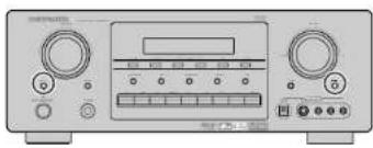
HOW TO RESET THE UNIT
Memory backup
- In case a power outage occurs or the power cord is accidentally unplugged, the SR8400 is equipped with a backup function to prevent memory data such as the preset memory from being erased.
Should the operation or display seem to be abnormal, reset the unit with the following procedure.
The SR8400 is turned on, press and hold the SELECT and S-DIRECT buttons simultaneously for 3 seconds or more.
Remember that the procedure will reset the settings of the function selector. Surround mode, delay time, TUNER PRESET etc., to their initial settings.
TECHNICAL SPECIFICATIONS
FM TUNER SECTION
Frequency Range .87.5-108.0 MHz
Useable Sensitivity .IHF 1.8 μV/16.4 cB
Signal to Noise Ratio .Mono/Stereo 75:70 dB
Distortion .Mono/Stereo 0.2:0.3 %
Stereo Separation .1 kHz/45 dB
Alternate Channel Selectivity .±300 kHz 60 dB
Image Rejection .98 MHz 70 dB
Tuner Output Level .1 kHz, +75 kHz Dev 800 mV
AM TUNER SECTION
Frequency Range 520-1710 kHz
Signal to Noise Ratio 50 dB
Useable Sensitivity Loop 400V
Distortion 400Hz, 30% Mod. 0.5%
Selectivity ±20 kHz 70 dB
AUDIO SECTION
Power Output (20 Hz - 20 kHz/THD=0.08%)
Front L&R 8 ohms 110 W / Ch
Center 8 ohms 110 W / Ch
Surround L&R 8 ohms 110 W / Ch
Surround Back L&R 8 ohms 110 W / Ch
Front L&R 6 ohms 135 W / Ch
Center 6 ohms 135 W / Ch
Surround L&R 6 ohms 135 W / Ch
Surround Back L&R 6 ohms 135 W / Ch
Input Sensitivity/Impedance 168 mV; 47 Kohns
Signal to Noise Ratio/Analog Input / Source Direct... 105 dB
Frequency Response
[Analog Input:Source Direct] 8Hz-100kHz(±3dB) Digital Input:96kHzPCM) 8Hz-45kHz(±3dB)
VIDEO
Television Format NTSC Input Level/Impedance 1 Vp-p75 ohms Output Level/Impedance 1 Vp-p75 ohms Video Frequency Response 5 Hz to 8 MHz (-1 dB) Video Frequency [Component) 5 Hz to 80 MHz (-1 dB) S/N .60 dB
GENERAL
Power Requirement AC 120 V 60 Hz
Power Consumption 648 W
Weight 32.0 lbs (14.5 Kg)
ACCESSORIES
Remote Control Unit RC1400 1
AA尺寸/电池 3
FM Follower Antenna 1
FM Antenna Converter 1
AM Loop Antenna 1
Specifications subject to change without prior notice.
DIMENSIONS
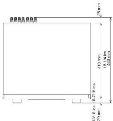
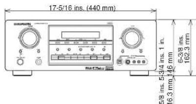
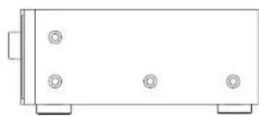
SETUP CODES
AMPLIFIER
Source button name:AMP
Brand name Setup code
Amstrad D105
Arcan 0296
Audplan 0296
Aolal
Cancer
GE0105
Genaxxa 0422
Gaurdi 0296
HarmanKendron051B
100
300358200358
LaT Coa8:0919
Linn 0296
Magnavox 0295
MaysnX 0918,0996
1
Micromega 0
Myryaz 0296
Cotrimus 0422
Panasonic 335
Phillips 0912 2006
0100000000000000000000000000000000000000000000
P#e 0040
Polk Audio 0819,0296
Realistic 0422
Revx 0296
Sone 0247
Sourdesign 0105
Technics 0335
Thorens 0296
Victor 0358
Wards 0105,0340
Yamashu 036
RECEIVER/TUNER
Source button name:AMP,TUNER
Brand name Setup code
ADC 0558
A2 1432018511614151688
Aing 1447
A03 147
Anam 1636
Apex Digital 1284
Audiolan 1216
Auditory 1715
Auditory 1216
Audio 1417
Addyox 1417
Dax 1856
B39 1256
Carbridge
Soundworks
Capeport 0558
Capit 1715 1115
0012 110
Centrex 1284
Denon 1387
Ferguson 0558
Fine Arts
Gardie 1216
RECEIVER/TUNER
Source button name:AMP.TUNER
Brand name: Systo code
Harman Kardoy 0137-1331
Inlrrn 0163-125
01023230000000000000000000000000000000000000000000000000
J8L 01371333120161014111530
JWC101.5584411522
KLH 147,1439
Kerwood 1340.1054
MCS 0068
Marquoy 1218129575591116
MgRv0-12003586170040000000000000000000000000000000
Marantz 215,066,116,1316
Micromega 1216
Muscnic 1116
Myrvad 1216
NAD 0347
M
NOCON1 416
Cnkyo 0162.C869.1325
Optimus 1050, 0558
Panasonic 1545,0036,1315,1790
Phillips 1216, 1236, 1116, 1293, 1295, 1310, 1316
Pore 1050,0041,058,1411
Polk Audio 1316
Pam Flora 1281
Prose1
Queer 066
RCA 1050,1638,1281,0558,1417
Saba 0558
Sansul 1118
Sceipd 0568
Sollie 6086
000 1365
Stereophonics 1050
Sunfire 1340
Teac 1417
Technics 1335, 1545, 0068, 1336
Toobinr
100
Tnson 1281
Thorens 1216
Uher 0558
Venture 1417
Voting 0101
Vicai 0101
W8650185.04
Yamaha 2203,1203,1358
CABLE
Source button name : AUX1
Brand name Setup code
ABC 030035
A000000000000000000000000000000000000000000000000000000
American Roll Smith 2023
Bn 320
Birmingham Cable 0303
Communications
British Telecom 0030
Cable & Wireless 1295
0304
Baoying 0504
Dingzai 0505
Director Toll: (6) 171
Filmnet 0470
General 0503,0837,0303
CABLE
Source button name : AUX1
Brand name: Saitong code
GoldSta:0171
HuaFing 2016-0300
1000000000000000000000000000000000000000000
InSrrn 0030
Jerro 0503.0837.C3C3.0030
LG 0171
MNet 0470
Memorex 0027
Motorola050108375351112
MTL4025
NIE 1095
Noos 0844
One 1095
PvP Stereo 0030
Visual Mol.
Vieae Mtna 026410871095
Panasop 00270350134
Pannane 2007
Panagri 027
Phillips 0332,0344
Pioneer 0904.1904.01
Pulsar 0027
Cusar 027
Bogal 2306,2400
Rega 000,000
Fune 0027
Sagem 3844
Samsung 0027.0171
Scientific Atlanta 030419605640035
SORY 1023
Stroop 2017
Stockcom
Supercable 0303
T 0030
Tel+1
Telpes1095
Tab. 532
FAX: 010-83279576
05169027
Trans PX 0303
Uniled Cable 0030
Zenith 0027,0552.0926
SATELLITE
DircrTV0419.0593.0666.1169.0274.0776.1776
0751084819311131116
Dish Network Systec 1032,0802
DishNet System 1002,000
Dn16 032,582
Distrale 011
Dream Multimedia 1264
Echoslar 1032,0802.0194.C423,0637,0880,0896
1118
F
Expo
Expresv C002515.9800
F10090
Finlxx 1492
Fracno 0896
Fuba 0423
GE0593
GOL 0523
G01 0632 Bolivics 99.98-14.98
Galaxis 0690,1138
Ganara Instrument 0896
Gald Box 0880
Gundle 1250,3874
HTS 0802
1000000000000000000000000000000000000000000000000000
Hughes 1169,0776,1776
Network Systems
Humax 08901203
InWider 0698
10.0000
VCU902
Kathrein 0150,0200,0227,0276,0695,1248
Koseimeyer 0200
Laborer 1323
1020
104472
Lorenzen
Magnavox 0751,0749
Manhattan 0482.1344.1119
Marantz 0227
11.1.2.1
Media:Sat 06:30
Memorex 075†
Melonic 0111
Mitsubishi
Molino,0836
Article history:
Received 2023
Received in revised form 16 September 2023
Myrbs 027
Next Level
| Source button name : DSS | |
| Brand name Setup code | |
| Nokia 0462, 0750, 0778, 1154, 1250, 1750 | |
| OctalTV 1032 | |
| Orbitech 1127 | |
| Pace 0482, 0674, 1202, 1350 | |
| Panasonic 0274, 0726, 0874, 1347 | |
| Panda 0482 | |
| Paystat 0751 | |
| Philips 1169, 0776, 1776, 0751, 1103, 0749, 0160, 0227, 0482, 0880 | |
| Pioneer 0830 | |
| Promax 0482 | |
| Proscan 0419, 0593 | |
| RCA 0419, 0593, 0862, 0170 | |
| RFT 0227 | |
| RadioShack 0896 | |
| Radola 0227 | |
| Radix 0423 | |
| SKY 0838, 0874, 1202 | |
| SM Electronic | 1227 |
| Sabre | 0482 |
| Sagom | 0847, 1141, 1280 |
| Samsung | 1303, 1136, 1044, 1319 |
| Sat Control | 1327 |
| Salvation | 1110 |
| Schwalger 1138 | |
| Seismik | 0423 |
| Siemens | 0200 |
| Sonry 0566, 1666, 0674 | |
| Star Choice | 0895 |
| Strong 1327 | |
| TPS 047, 1260 | |
| Tantec 0482 | |
| TechSim | 1126, 1127 |
| Telestar 1127 | |
| Thomson | 0462, 0880, 1073, 1318 |
| Topfield | 1233 |
| Toshiba | 0776, 1776, 0617 |
| UltimateTV | 0419, 0666 |
| Uniden | 0751, 0749 |
| Univerum | 0200 |
| Vontana | 0227 |
| Wisi | 0200, 0423, 0482 |
| XSat | 0150 |
| Zehnder | 1102 |
| Zenith | 0883, 1883 |
| Source button name : CD, CDR, MD |
| Brand name Setup code |
| Aiwa 0184 |
| Arcam 0184 |
| Audio Research 0184 |
| AudioTun 0184 |
| Audiolab 0184 |
| CD/CD-R PLAYER |
| Source button name : CD, CDR, MD | |
| Brand name Setup code | |
| Gensoxo | 0059, 0332 |
| Goodmans | 0332 |
| Grundig | 0184 |
| Harman/Kardon | 0184, 0200 |
| Hitachi D058 | |
| JVC | 0099 |
| Kenwood | 0798, 0653, 0055, 0064 |
| Kroll | 0184 |
| LXI | 0332 |
| Limn | 0184 |
| MOS | 0056 |
| Magnavox | 0184, 0332 |
| Marantz 0653, 0056, 0184 | |
| Matsei U184 | |
| Menorax | 0332 |
| Meridian | 0184 |
| Micromega | 0184 |
| Micro 0027 | |
| Mission 0184 | |
| Myryad | 0184 |
| NAD 0027 | |
| NSM | 0184 |
| Naim | 0184 |
| Onkyo 0895 | |
| Optimus | 0027, 0059, 0064, 0208, 0332 |
| Panasonic 0056 | |
| Philips 0653, 0184 | |
| Pioneer 0059, 0332 | |
| Pok Audio | 0184 |
| Proton 0184 | |
| OED | 0184 |
| Quad | 0184 |
| Quasar | 0056 |
| RCA 0059, 0206, 0332 | |
| Realislo 0205 | |
| Revox | 0184 |
| Rolei | 0184 |
| SAE 0184 | |
| Sansui 0184, 0332 | |
| Sanyo | 0206 |
| Scott | 0332 |
| Sears | 0332 |
| Sharp | 0888, 0064 |
| Simaudio | 0184 |
| Sonci Frontiers | 0184 |
| Soncy 0517, 0027 | |
| Symphony | 0332 |
| TAG McLaner | 0184 |
| Tandy | 0059 |
| Technics | 0056 |
| Thopens 0184 | |
| Triusie | 0184 |
| Universum | 0184 |
| Victor 0099 | |
| Wards 0184 | |
| Source button name : TV | |
| Brand name Setup code | |
| MARANTZ 0001TV1 (TV, VDP) | |
| MARANTZ 0002TV2 (Plasma) | |
| AGB 0543 | |
| AOC 0478, 0120, 0207, 0087, 0057, 0205, 0036,0113, 0135 | |
| ASA 0131AWA 0036Acura 0036Addison 0115, 0135, 0680Amaral 0120, 0490, 0195Adveni 0788 | |
| Aiko 0119Akai 0839, 0729, 0057, 0036, 0235, 0388, 0543Akura 0291Alba 0036, 0064, 0388, 0635America Action 0207 | |
| Amphis 0778 | |
| Amisrad 0198, 0036, 0064, 0398, 0439, 0450, 0543Anam 0277, 0207, 0056 | |
| Aram National 0277, 0577 | |
| Antisch 0036Apex Digital 0775, 0792, 0794Audiocsonic 0064, 0136Audiovox 0478, 0207, 0113, 0650Bang & Urban 0592 | |
| Basic Line 0036Baur 0064, 0388, 0539 | |
| Baysonic 0207Beaumark 0205Beko 0397, 0513, 0741, 0742Bell & Howell 0131Beot 0094Blaucunki 0222Blue Sky 0895, 1064Bonssec 0274Bradford 0207 | |
| Brandt 0136, 0362 | |
| Broksonic 0883, 0490 | |
| Bush 0036, 0064, 0398, 0451, 0685, 1064 | |
| CCE 0064 | |
| CGE 0274CTC 0274 | |
| CXC 0207 | |
| Candia 0057Camelsole 0057 | |
| CXC 0207 | |
| Candle 0057Camelsie 0057 | |
| CXC 0207 | |
| Carver 0081, 0197 | |
| Cascade 0036 | |
| Calhay 0064 | |
| Celebrity 0027 | |
| Celera 0792 | |
| Centurion 0064 | |
| Changchong 0792 | |
| Ching Tai 0036, 0119 |
TV
Source button name : TV
Brand name Setup code
Chun Yun 0027,0207,0036,019
Chung Hsin 0207,0080,0135
Cimine 0036
Cinera 94
Citizen 0087,0057,0119
Clairion 2017
Claryrox 0C64
Clerronic 0274,0387
Cordna 0367-0397
Ceroc 885
Cortes 2017, 0636
Craig 9592
12:00- 12:03
CRESSEY OCE
Crewm 0207,0038,0064,0397,0445
Curlis Matthes 0074,0081,0181,0478,0120,0087,0723
2057,0172,0193,1174,1374
Daww0 0181,0478,0207.0057.0205.1688.0036
3064,0119,0135,0197,0401,0650,0661
Densai 0264
Daylog 0036
De Graaf 235-1575
Denn 2064,2543
Devila 2004, 0345
Doron
Denon 0178 Dingshan 0624
Dilution 0064 Dirl 0252764
Daxi 0536,064 Bayer 0514
Dunion 6049
Dwin 0741
D 07
ECE 064
Ebe 0286
Electroband 0027
Ein 064,0575
Elite 0347
E1a 0C36
Emerson 0181,0263,490,0207,0205,0386,0550
Envision 0057,0840
Epson 3860
Eries 0664
Ether 0057.0036
Eink.0326
Europhan 05/43
Euogon 0543
Fegc91 0664.0100.0138,0263,0314,0382,0587
Fidelity "388
Finlandia 0235, 0373
Finux 064,0131,0132,0373,0543
Firstar 0263,0036
Firstline 0036.0274.0595
Fisher 0181,0131.02
Flect 0482
Fornert 0084,334
Fortress 0120
Froptech 0190,0274,0281
Fuitsu 0710.0836
Furai 0207,0198,0291
Futuretech 0207
TV
Source button name: TV
Brand name Setup code
0074.0078.0478.0207.0057.0205.1481
0119.0587.1174.1374
GEC 0264.0543
Galeway, 1782
Galaxy:1986
Garaya 0190
00440057
GokSty.1181705702950640135P04
Goodman 06442084412661
000000000000000000000000000000000000000000000000000000000
Gorilla 0357 Geronimo 0080.0107
Graeert 0195-0288
Grae 0196,0388 Gronata 0084,025,0268,0542
Granada 0604,0235,0305,0393 Grandia 0587
Grandma 0637
Cunning 0641
Grind 0684,0222.0314.0983.0614
Groupy 0207
HCM 0338.0439
Hallmark 2205
Hankock 0207, 0057, 0205
Hanseabo 064,0347,0388,0455,0583
Hantarox 3543
Hamran/Kamun 0081
Hartman 057
The Bank Havamy 0120
HeioKth 0478
Hiroori 0125
Hinaii Hinao 0482
10205702051173017312620260119
0132.0136.0190.0252.0383.0508.0575
0625
HuaTun 0036
Huairu 0401
Hypyscn 0364,0291
ICE 02910388
ITS 0398
TT 0196,0388,0575
Impairia 0274,0397,045
Inga acq 0064
inlimits 0381
Inale 0190
InnoH 0543
Inpro 0064
int68 0044
Interluk 02640190027403880539
Intortion 064,091,274
同意00641B)0061
BDE 0381ICG 2027
JG 0027 BVC 24902080203806300715
JVC 0450,0860,0396,0880,0710 Joan 0183,0078,0263,0396,0119
Jetsen C768
KEC 0207
KTV 207.2057
Kaisui 0036
Kansch 2130
Karcher 0637
TV
Source button name: TV
Brand name Setup code
Kalthein 0563
Kerdn 006
Kenwood 0057
Kneissal 0286-2462
Koln 200700800135
Kornel0064
Kapker 003
Kowda 003
LAS Electronic 0835
L008700572005006401250741
LX1 0074.0817181018205
Lawn 0964231
Lc
Lseik&T 604
1
LoeAe 0539
1
L067 0383,03881.524.00000000
M Electronic 038.2064,0131,0132,0136,0190,0314
03/3,0401,0507
MGA 0177.0057.0205
MTC 0087.0057.0539
Magnadyne C274,0543
Magnalon 0543
Magnavor 0081,0057,1481,1281
12910347
Mark 0064
Matsui 0336,0064,0235,0328,0514,0543
0000.0000.0000.0000.0000.0000.0000.0000.0000.0000.0000.0000.0000.0000.0000.0000.
MaiuHia 0271,0677 Mediher 5954
Medi 604 Median 005-0985-1084
0801693,685,1084
Magatron 0205.0172
Memorex 0181,0277,0430,0177,0205,0336,1064
Matz 0474
Micromaxx 0835
Microstar 0835
Midland 2074,0044,0078
Minerva 0514
Minoka 0439
Mnsubish 0181,0277,0120,0263,0207,0177,1277.
0057.0205.0135.0539.0863
Wear
Mortarla 0120
Material:
Mulltac 0207, 0038
Morgad 0563
MAD 01832050388093
5142.5183.7018.057.0705.0705.6193
NEC 0181,0183,0078,0057,0205,0036,0197 0420,0524,7731
(042)
NE 0064NET 0413
N1C 0119 No.1000062547589
Nackernann 0064,583
Nutz 2051
NE.SAL 00641235899999999999999
Newave 0120,0205,0306,0119
Nikkei 0064,0231
Nikke 0057.22
Nkla 0368.0500,0507,0575,0658
Norcent 0775,0851
Nordmende 0136,0314,0587
Oceanic 0190,0388
TV
Source button name: TV
Brand name Setup code
Onya 0207-0463
Optimus 0181,0277.0193.0677
Optonica 0120
Onion 0263.0490.0664.0347.0543
Osaki 0291
Ottos Versand 0064,0347,0583,0583
Palladium 0397,0445
Panama 0291
Panasonic 0081,0277.0078.0064.1190.0677.1437
Batterie Coema 0265,0347
Pursa 0038
Penery0074.0183.0178.0082.0057.0225.1374
Pedi 0347
Pbllco
0067,0406,0207,0087,0208,0172,1008
004.0274 Pblics 2001-2007
Philips 001,002,007,008,029,1481,0084, 0115,6105,6141,6532,674
019 Phonols 0064
P104 2057
Pilot 0097
Diplom 0126
Pioneer 0193,0136,0190,0314,0708,0787,0893 Patron 2645
Pondard 0119 Dontain Dines 0561
Prandoni-Finna 0543 Dana 2789
Prima 0.48
Prrn
Prote 036,038
Treason 057
Proscan 0674 Detach 0236-0864-0974-0984-8415-2625
Ploch 0036,0064,0274,0291,0245,0835
Protein 100g 24:1
Pusar 004
Q2006277,0078,0877
Quie 064,0137,0388,039
R-Line 0054
RCA 0074,0027,0057,0205,1474,1481,0117
0118.0706.1074,1174,1274,1374,1574
RFT 0455
RadioShock 0074,0181,0207,0057,0205
Ratiola 0064
Radiomarelli 0543
Realistic 0181,0207,0057,0205
Redifusion 0S88
Recc 0741
Revox C064
Fox 0190,0286,0291
Roadstar 0036, 0291, 0445
Hunco 0544,0557,0524,0630
SBR 0064
SEG 0291,0895
SE 0543
SKY 064
SSS 0207
Saba 0136
Saco 0265
Sagem 0637
Saishe C036,0291,05-3
Salora 0190,0383,0388,0575
TV
Source button name: TV
Brand name Setup code
Samher 1543
Sarrp0181,0120,0057,0205,0198,0038,0113
0677,1782
Samsung 0181,0037,0839,0729,0057,0225,0036
0064,0117,0119,0291,0397,0583,0614
0645,0793,0841
Sansel 0478
Sansu049C
Sanyo 018102070131023503860826
SchaBing 0388
Schneer 0064274388695
Scott 005
Scoll 3262-3267-3268
Bocan 2614,0831,618
0074061.018101832230196
Seleco 0196,0286
Semivax 0207
Semp 0183
Sharp 0120.0057, 0677
Shen Ying 2038
ShengChiaC120.C263.0036
Staem 0543
Sierans064222
Sindraprna 0543
Chongqing 6302
Sikhan L 1838
Sikhan L 1838
Skyhart 0237
Skysworth 0084
Solayox C190 Solayox 200
Sonicron 0235
Sonoko 0036,0064
Sonolar 6190
Soybean 626
SOTBC DUEA
Sony 1127,0027,0677,0861.15321878
Sounddesign 1207.1205
Soundwave 0064,0445
Sowa 0183.0078,0087,0205,0119
Squareview 0198
Standard 0038
Starlite C207
Stern 0190.0296
Supreme 0027
Sylvania 0081,057,0198
Symphonic 0207.0138
Synco 0027,3478,0120,0087,0205.0113
Sysline 0064
T-A 6474
TCM 0835
TMK 8205
TNC 2044
TYS 6480
Tacico 0255.0036.0119
Tai Yi C036
Tangy 0120.0130
Tashikp 019.0677
Talung 0081,0181,0183,0078,0087,0035,0064
1543
TV
Source button name : TV
Brand name Suhp codes
Teac 0036.0084.0291.0438.0445.0482.0695
1064
Tac 0274
Tachnema 0347
Technics 127700780677
Cormen, MI 41702 Tachybot 2008
Taco 078.0120.0205.036.0119.0291.0680
Taknka 7081,0327,0177,0787,0113
Taekun 07201136020080820853
Telkomaker 2347
Taluk 2026
1918ec0036
Tansal 0347
Tara 3057
Thomson 1474,0136,0314,0587,0652
Thom 0064,0131,0389,0539
Toshina 0181,0183,0037,1283,0535,0645,0677
0859,1383,1683,1731
Triumph 0543
Tunlex0057.C038.C119
Uher 0347
Universum 0084,0131,0132,0291,0373,0397,0519
Vector Research 0057
Vestel 064
Victor 0277,0090,0677,0580
Videoat C274
Vickron 3091
Victech 0205
ViewSckc 1782
Vision 0347
Voxson 9190
Walham 0383
Wards 2081.0057.0205.0893
Wolson 2064,0847
Wuyang 0183
White Westinghouse 3490,0064,0347,0650
Yamaha 0057.0796.086C
Yashe 0277
Yao 0084.0291
Zanib 0046243002050119
VCR
Source button name : VCR
Brand name Setup code
ASA 2084.0108
Adams 503
Admixture 5073
Adjuvant 2017
Advenlria 5027
Allele 0826
AIO 005 Aiva 2054,2017,0324,0175,0378
AWA 0064,0027,0334,0573,0375
Akai 0068,00143
Akan 0056,034E Akiha 2059
Aha 0089
A000000000000000000000000000000000000000000000000000000000000000000000
America Jioh 2062
American High 5082
Amethod 2077
VCR
Source button name : VCR
Brand name Setup code
Anam 0364,0267,0305,0253,0507
Aram National 02531589
Antech 0099
Asba 0267
A
Auditory 0044-0305
Aolivai 5694,6363Baird 002701310068
Basic Line 70997275
Basic Line 00530053 Requers 007
Bol & Hounel 0111
Dy
Bilaparki 0233 Daday 9857
Brand: 0547 Design & Fabrication: 2689
Brand Electronic 0028
Bolzano 3211
BROKING 0217,0375,1506 Pursih 0209-0305-0377
BSS0098,0365,079 005200
CCE 0099,0305 CEE 0107
CGE 0027 A股 1998
Calix 0064
Caron 0082
Canvar 0108 Credible 000
Cimline 3099
Cinera 0305
Citzen 0064,5305,1305
Coll 0099
Comoltech 0379
Craig 0054,0074,0267.0099
Crown 0099,0305
Curtis Mathes 0097,0062.01
Cybersex 0287
Cyrus 010
DaeWoo 0072.0131.0305.0669.1305
Darsal 0099
De Graaf 0089
Decca D108, 0927
Deor 0689
Dual 0658
Dunapol 0108.0027.0131
Dynatc 0027
ESC 02870305
100 Elsacch 0929
Electrophore 0054
Electrophoric 0654
Echinoepithelioma 964
Emetex 0059
Emperson 0622064021102670220270070
030513051506
Fergusson 0068, 0347
Fidelity 3027
Financia 0108.0131
Einxu 318,027.969.C
Firstline 0064.0072.0073.009
Fisher 2074
Fuii 0062.0060
Fuitsu 0072.0027
Fiscal 2007
GE 0087.0062.0267.0834.1062.1087
VCR
Source button name : VCR
Brand name Setup code
GEC 010
Garrard 002
Genera 007
Gg Video £459
GoldHard 0098
GoldStar0064,0252,0507,1284
Goodman 0664.027.099.1305
Gocnents 053
Cn07 0867
Grade2 Goranda:0178-0131
Grandio 0064027093
Grundg 0106,0095253.0374
HCM0098
H-O 037
Hanseatic 006
Harley Davidson 002
Hartman/Kardson 010
Harwood 0C99
Hinari 0267,0099,0375
Hitachi 0064.0267.0027.0069.0088
Hughes 006
Network Systems
Hypson 009
TT 026
TV 006
Imperial 002
interfunk 010
JVC 0072,0094.0068
Jensen 056
KEC 0064.0305
KLH 009
Kaisui 039
Kenwoo 0034,0088
Kodak CO62,0054
Klein 007
Kornal 009
1.600000
X)066
LFP 030
1000000000
Lodys 0027
Lawa 006
Lc067095
Lxur 007
ELAL 0675,0187,0274A Electronic 0077
IN Electronic 022
EMI 068
4AGA02671077
AGN Technologik 028
MTC 0267027
Magnasonic 1385
Magnayox062066010800271838
Magnus 9287
Manesih 0072, 0899
Mazan 006
Marie 066
VCR
Source button name : VCR
Brand name Setup code
Matsui 0375.0379
Maiu
Median 0375
Mery 2023-064-0875-0963-0974-2067-2027
2131033403751264
Metaphis 2089
Me:0643741589
2008年1月16日
Mitsubishi0108,0094,0070,0088,0834
Ninssn01063-0575
M100720076
Mortech 002
Murphy 002?
Myryed 01
NAD 0131
NEC0062,0064,0075,0131,0094,0068
National 0253
Neckermann C108
Nescc 2099
NewA
Nikon 0064
Nimie 0634 Noclex 0267
Nokia 026701310068
Nordmance 0068,0347
Organic 2027,0068
Cnane 2342-9375
A00000000000000000000000000000000000000000000000000000000000000000000000000000
Optipus 002,033 Optipus 0054075011459
00064879375149900000000000000000000000000000000000000000000000000000000000000000000000
OnH 0271,6375.6375 OnG 0640237099
G7004027395370000000000000000000000000000000000000000000000000000000000000000
Old Versus 0168 Balladium 0224,0268,0299
Panoan 0763-9757-2753-5642-1052-1589
Panasonic Co. Co., Ltd 00269
PaeleMarconi 068 Renson 076207640267095910821384
Fenney 60025
Bardex 00689
Remex 6032
Parlo 0227
Phillip 0662
Phillips CO62.01C8.0645.1108.1208
Phorola 0138
Prol 064
Pponer 0108.0063.0094
Palk Audio 0108
Profinitronic 0267
Proline 0027
Proscan 097,1087
Prolec 0099
Pular 0056
Pty 0108
Quasar 0062,1962
Quiege 0108
BCA 087.062.0267.0368.0834.1062.1087
BacbioShack 2027
Bidipl 0108
Baxix 0564
Bande 0664
VCR
Source button name: VCR
Brand name Setup code
Realistic 0062.0064.0075.0074.0027.0131
Reac 0375
ReplayTV 0641.0643
Re 0068
Roadstar 0064,0267,0099,0305
Runco 0068
SBR 0108
SE0257
SEI 0108
STS 0069
Saba 0068.0347
Salpra 007
Sarco 0064.0075
Samsung 0267,0072,0459
Sanky 0075,0066
Sansui 0027.0094.0068.1506
Sanyu 0074.0287.0131
Saville C379
Schaup Loez 0027.0131.0068
Schneider 0108.0027.0039
Scott 0211.D072.D079
Sears 062,064,074,0027,0069,0131,1264
Salco 0068
Samp 0072
Shap 0375.0834
Shirtroom 0131,0595
Shoqun 0267
Slemns 0064 0108 0131
Siva 064
Sincar 0072.0099
Sinudyna 0108
Sonic Blue 0541,0643
Sanjee 0061
Sory 0062.0590.060.0027.0563.1259
Surkai 0375
Sunstar 0027
Suntronic 0027
Sylvania 0062.0108.0027.0070.1808
Synthetic 0027
TMK0267
Tandy 0027.0131
Tashiko 0364,0027
Diamond 0795
Dinitex 6699
Emerson 0818
Talung 0108.0072.0027.0094.0088
Teac 0027,0068,C9C5,334,0669
Technics 0562.0253
Teco 0062.0064,0075,0088
Teknika 0362.0064.0027
TeLeavia 0068
Teefurken 068,0347
Tenosal 0099
Tensai 0327
Thomas 0027
VCR
Source button name : VCR
Brand name Satup code
Thomson0187.0994.0683.347
Thor 0131,068
Two 06456683
Tpsjiba 0108.0072.0034.0070.0068.0872
Television 0064.0267
Uher 0267
Unitech 0267
Universum 5064,1158,0287,0027
VCHOR 0001000000000000000000000000000000000000000000000000000000000
Victor 0994068
Video Concer's 007
Wideomatic 0764
VideoMagic 1287
Villain 027
Wards 0087,0062,0075,0074,0108,0267,0377
0069.0098
While Westinghouse 009
XR-1003 0062.0027.0099
Yamaha 0088
Yamshi 0099
Yokan 0099
Yoko C267
Zeith 0966.0960.00
DVD
Source button name : DVD
Brand name Setup code
MARANTZ DVD 0001
MARANTZ DVD 0002
Acoustic Solutions 0757
Alba 0744
Amstrac 3740
Ape Digital 0693.0744.0782.0821.0823.0857,1127
Blaupunkt 3744
Blue Parade 0599
Bush 0740
Centrex 0399
Clantrion 3815
CyberHome 0741
DVD200 0548
Daewco 0811,0797
Dansai 0797
Decca 0797
Denen 0517
Enterprise 0613
Fisher 0697
GE 0549,0744
Go Video 0742
GoldStar 0758
Grodiente 0678
Greenhill 0744
Guang 0563
Hiroshi 0629
Pittach 5600
Lilleferer 0500
DVD
Source button name : DVD
Brand name Setup code
JVC 0585.0650
KLH 0744
Kenwood 0517, 0561
Kess 0678
LG 0768
Lim10795
Magnavox 0530,0702
Memorex 0858
MICO 0750
Microsoft: 0543
Minlek 0744
Mitsubishi 0548
Muslex 0757
Nesa 0744
Onkyo 0530
Oritran 0678
Palsonic
Panasonic 0517,0658,1388
Philips0530.0568.0673.0891
Pioneer 0552,0598,0658,0659
Pcik Audio 0566
Proscar, $549
Owastar 0678
BCA 0549.0588.0744
Botei 3650
SM Electronic 0757
Samsung 0600
Sangbo 6687
Share 0657
Shermon 0797
Shipsynir 0560
Sino 0611
SAPAR 9017 Spa 0560,0801
Surya 6503,247,894
SYMBOL 0792 Talung 0797
Tenc 0598.0744
Technics 0517
Teta Digital 0598
Thompson 2549
Tophia 05
Urban Concepts 0530
XRay 05/0
Xue:0517,0568,0572
Zanith 0530.0618.0769
Zus 0511
DIRECT BUTTON FUNCTIONS
Source button name : AMP
| PAGE Command Note | ||
| PAGE 11 | AUTO SELECT | AUTO SURROUND |
| 2 DD | SELECT DOLBY MODE | |
| 3 DTS SELECT DTS MODE | ||
| 4 EX/ES SELECT EX/ES | ||
| 5 DIRECT SELECT SOURCE DIRECT | ||
| PAGE 21 | MCH-ST SELECT MULTI CHANNEL STEREO | |
| 2 STEREO SELECT STEREO MODE | ||
| 3 VIRTUA SELECT VIRTUAL MODE | ||
| 4 CS-II | SELECT CS-II/MODE | |
| 5 HT EQ SELECT HT EQ | ||
| PAGE 31 | NIGHT NIGHT MODE ON/OFF | |
| 2 BASS + BASS - | ||
| 3 BASS - BASS - | ||
| 4 TREB + TREBLE + | ||
| 5TREB - TREBLE - | ||
| PAGE 41 | MULTI MULTI ROOM ON/OFF | |
| 2 M-SPKR MULTI SPEAKER ON/OFF | ||
| 3 A/D SELECT ANALOG/DIGITAL | ||
| 4 V-OFF VIDEO OFF | ||
| 5 AUDIO BILINGAL SELECT | ||
Source button name : TUNER
| PAGE Command Note | ||
| PAGE 11 | FM SELECT FM | |
| 2 AM | SELECT AM | |
| 3 LW | SELECT LW | |
| 4 T_MODE | SELECT MONO/STEREO | |
| 5 BAND SELECT RADIO BAND | ||
| PAGE 21 | SCAN - FREQUENCY SCAN UP | |
| 2 SCAN - | FREQUENCY SCAN DOWN | |
| 3 T_MODE | SELECT MONO/STEREO | |
| 4 P-SCAN SELECT PRESET SCAN | ||
| 5 P-INFO | SHOW PRESET INFORMATION | |
| PAGE 31 | DISP RDS DISPLAY | |
| European model only | 2 PTY | RDS PTY |
| 3 AF | RDSALTERNATE FREQUENCY | |
| 4 STM | RDS STATION MODE | |
| 5 DWR | RDS DSR WAVE LANGUAGE | |
| PAGE 41 | MULTI MULTI ROOM ON/OFF | |
| 2 M-SPKR MULTI SPEAKER ON/OFF | ||
| 3 | ||
| 4 P-SET + | PRESET UP | |
| 5 P-SET - | PRESET DOWN | |
Source button name: DVD
| PAGE Command Note | ||
| PAGE 1 1 | MENUS SELECTS MAIN MENU | |
| 2 AUDIO SELECT LANGUAGES | ||
| 3 SUB-T SELECT SUB TITLE | ||
| 4 10+ DIGIT ENTRY +10 | ||
| 5 TRAY | TRAY OPEN/CLOSE | |
| PAGE 2 1 | SETUP SELECTS SETUP MENU | |
| 2 ANGLE | SELECTS ANGLE | |
| 3 OSD | ACTIVATES ON SCREEN DISPLAY | |
| 4 FF | FAST FORWARD | |
| 5 REW | REWIND | |
| PAGE 3 1 | SLOW SLOW FORWARD | |
| 2 L PLAY | LAST PLAY | |
| 3 SHUFFLE | SHUFFLE PLAY | |
| 4 REPEAT | REPEAT MODE | |
| 5 A/B | REPEAT A TO B | |
| PAGE 4 1 | RETURN RETURN TO MENU | |
| 2 T/C | TITLE AND CHAPTER | |
| 3 3-D | SURROUND ON/OFF | |
| 4 TITLE | SELECTS TITLE MENU | |
| 5 ZOOM ZOOM MODE ON/OFF | ||
Source button name: CD
| PAGE Command Note | ||
| PAGE 11 | DISC + CD CHANGER NEXT DISC | |
| 2 DISC - | CD CHANGER PREVIOUS DISC | |
| 3 SHUFLLE | SHUFFLE PLAY | |
| 4 REPEAT | REPEAT | |
| 5 TRAY | TRAY OPEN/CLOSE | |
| PAGE 21 | TEXT ACTIVATE TEXT FUNCTION | |
| 2 AMS | AUTO MUSIC SCAN | |
| 3 SCROLL | SCROLL/RECALL | |
| 4 FF | FAST FORWARD | |
| 5 REW | REWIND | |
| PAGE 31 | DISC 1 | CD CHANGER DISC 1 |
| 2 DISC 2 | CD CHANGER DISC 2 | |
| 3 DISC 3 | CD CHANGER DISC 3 | |
| 4 DISC 4 | CD CHANGER DISC 4 | |
| 5 DISC 5 | CD CHANGER DISC 5 | |
| PAGE 41 | UNIT SELECT UNIT No. | |
| 2 TITL-S | SELECT TITLE SEARCH | |
| 3 TRACK | SELECT TRACK No. | |
| 4 CATGRY | SELECT CATEGORY | |
| 5 P-MODE | SELECT PLAY MODE | |
Source button name : VCR
| PAGE Command Note | TV/VCR SELECT TWICE NORMAL PLAYBACK SPEED | |
| PAGE 11 | ||
| 2 XPLAY | ||
| 3 SLOW SLOW PLAYBACK SPEED | ||
| 4 STILL | STILL FRAME | |
| 5 EJECT EJECT | ||
| PAGE 21 | DTR ONE TOUCH RECORDING | |
| 2 AUDIO SELECT AUDIO MODE | ||
| 3 SKIP | SKIP TO NEXT PROG.MARKER | |
| 4 FF | FAST FORWARD | |
| 5 REW | REWIND | |
| PAGE 31 | VIS + VHS INDEX SERCH NEXT | |
| 2 VIS- | VHS INDEX SERCH PREVIOUS | |
| 3 | ||
| 4 | ||
| 5 | ||
Source button name : CDR
| PAGE Command Note | ||
| PAGE 11 | INPUT SELECT | INPUT SOURCE |
| 2 INCR | INCREMENTS TRACK No. | |
| 3 SYNC-R | ACTIVATE SYNCRO RECORDING | |
| 4 PROG | ACTIVATE PROGRAM MODE | |
| 5 TRAY | TRAY OPEN/CLOSE | |
| PAGE 21 | SCROLL SCROLL/RECALL | |
| 2 FINAL | FINALZIES(WRITES TOC) | |
| 3 BLANK RECORDS BLANK | ||
| 4 FF | FAST FORWARD | |
| 5 REW | REWIND | |
| PAGE 31 | BLANK RECORDS BLANK | |
| 2 REPEAT | ACTIVATE REPEAT MODE | |
| 3 | ||
| 4 | ||
| 5 | ||
Source button name : TAPE
| PAGE Command Note | ||
| PAGE 11 | TAPE-A SELECT TAPE DECK A | |
| 2 TAPE-B SELECT TAPE DECK B | ||
| 3 DIR | AUTO REVERSE DIRECTION | |
| 4 TIME | TIME DISPLAY | |
| 5 TRAY | TRAY OPEN/CLOSE | |
| PAGE 21 | AMS AUTO MUSIC SCAN | |
| 2 | ||
| 3 | ||
| 4 FF | FAST FORWARD | |
| 5 REW | REWIND | |
www.marantz.com
You can find your nearest authorized distributor or dealer on our website.
JAPAN Marantz Japan, Inc. 35-1 Sagami Ohno 7-Chome, Sagamihara-shi, Kanagawa 228-8505, Japan
U.S.A. Marantz America, Inc. 1100 Maplewood Drive, Itasca, IL 60143, U.S.A.
EUROPE Marantz Europe B.V. P.O. Box 8744, 5605 LS Eindhoven, The Netherlands
Manufactured under license from Dolby Laboratories. "Dolby"; "Pro Logic" and the double-D symbol are trademarks of Dolby Laboratories. Confidential Unpublished Works. © 1992-1997 Dolby Laboratories, Inc. All rights reserved.
marantz
is a registered trademark.

01/2004 ECMf 06Bw851250Printed in China