ORI28314 - Remote control toy Team Orion - Free user manual and instructions
Find the device manual for free ORI28314 Team Orion in PDF.
User questions about ORI28314 Team Orion
0 question about this device. Answer the ones you know or ask your own.
Ask a new question about this device
Download the instructions for your Remote control toy in PDF format for free! Find your manual ORI28314 - Team Orion and take your electronic device back in hand. On this page are published all the documents necessary for the use of your device. ORI28314 by Team Orion.
USER MANUAL ORI28314 Team Orion
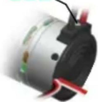
natural_image
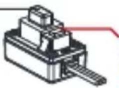
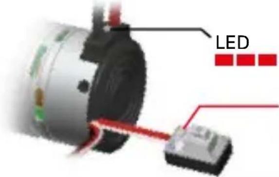
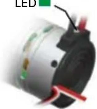
Close-up of a metallic electric motor with visible branding and wiring, no readable text or symbols beyond branding.CONNECTIONS

text_image
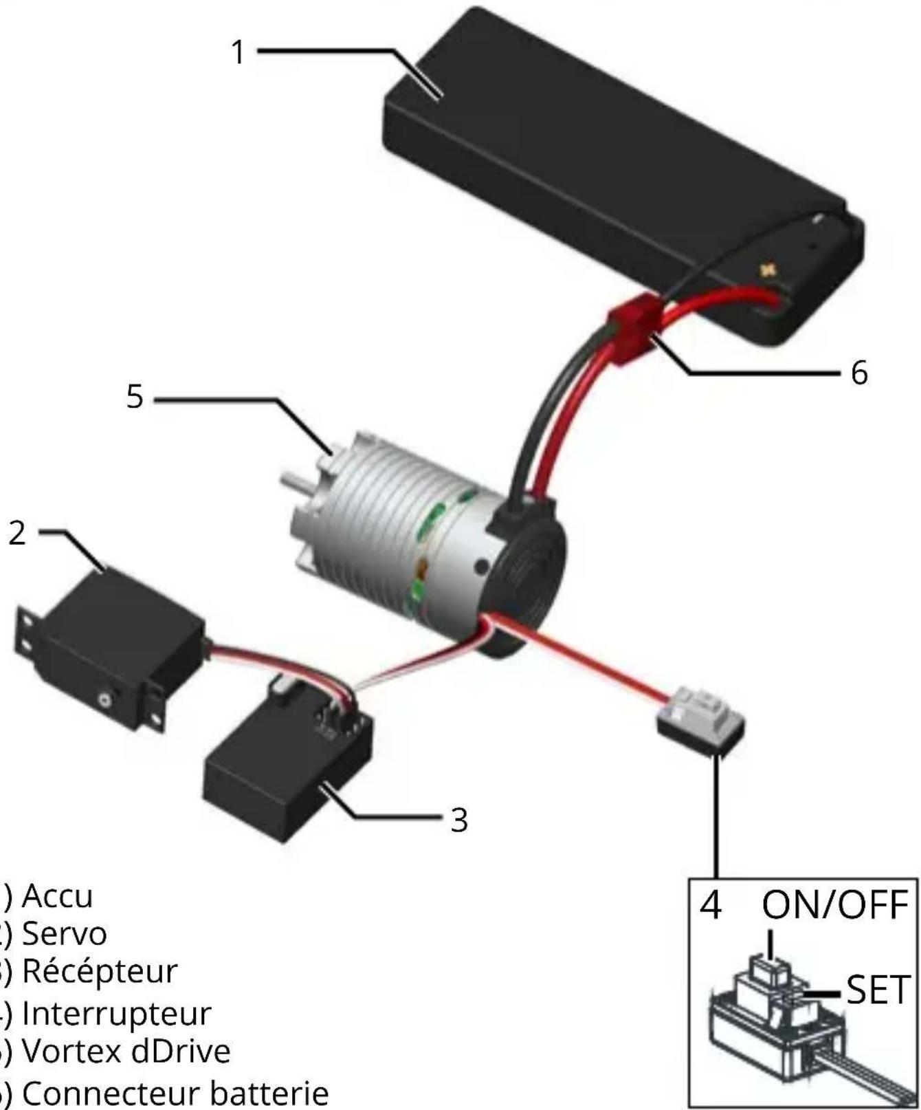
1 2 3 5 6 4 ON/OFF SET Battery Servo Receiver Switch Vortex dDrive Battery Connector1) Battery
2) Servo
3) Receiver
4) Switch
5) Vortex dDrive
6) Battery Connector
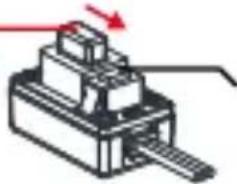
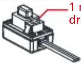
CALIBRATION STEP 1
1
ON/OFF
natural_image
Pure mechanical component diagram without any text, numbers, or symbolsPress and hold the SET button
2
Switch ON
natural_image
Pure mechanical component diagram without any text, numbers, or symbolsKeep pressing the SET button
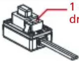
3
text_image
LEDRelease as soon as soon as the red LED starts to blink
CALIBRATION STEP 2
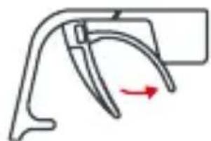
natural_image
Simple line drawing of a tool or bracket with curved blades (no text or symbols)2

natural_image
Diagram of a curved mechanical component with a red arrow indicating direction (no text or symbols)3
natural_image
Pure mechanical component diagram without any text, numbers, or symbols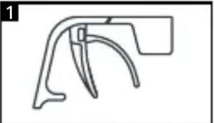
natural_image
Simple line drawing of a mechanical component or bracket (no text or symbols)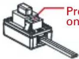
text_image
Pro on2
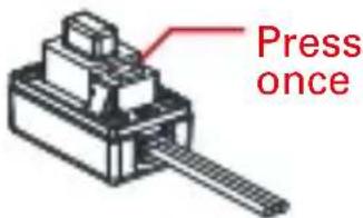
text_image
Press once3
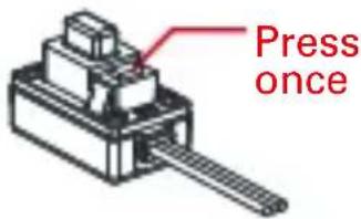
text_image
Press once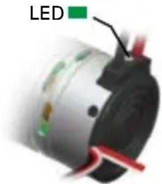
natural_image
Close-up of a mechanical component with LED indicator and red wires (no text or symbols visible)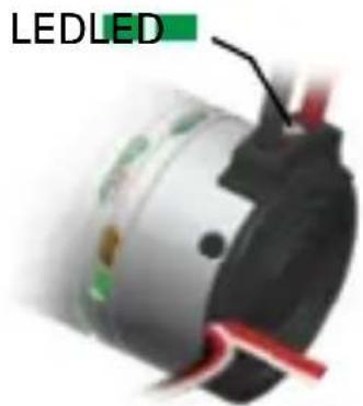
natural_image
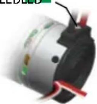
Close-up of a metallic cylindrical device with red wires and a green label reading 'LEDLED' (no other text or symbols visible)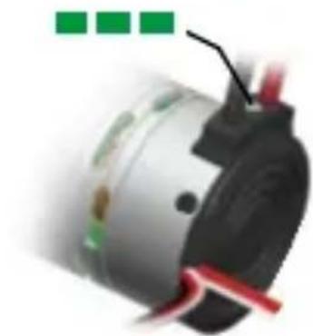
natural_image
Close-up of a mechanical component with green and red markings (no visible text or symbols)PROGRAMMING YOUR ESC
text_image
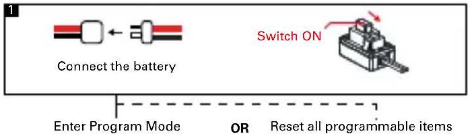
Connect the battery Switch ON Enter Program Mode OR Reset all programmable items
text_image
2 LED blinks Press the SET button for 1s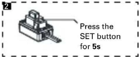
text_image
2 Press the SET button for 5sChoose the parameter you want to change
text_image
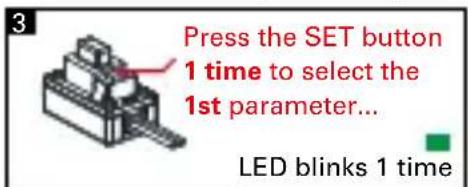
Press the SET button 1 time to select the 1st parameter... LED blinks 1 time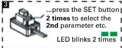
text_image
... press the SET button 2 times to select the 2nd parameter etc. LED blinks 2 times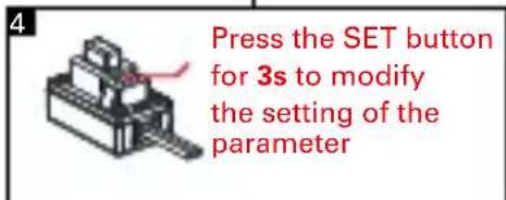
text_image
Press the SET button for 3s to modify the setting of the parameter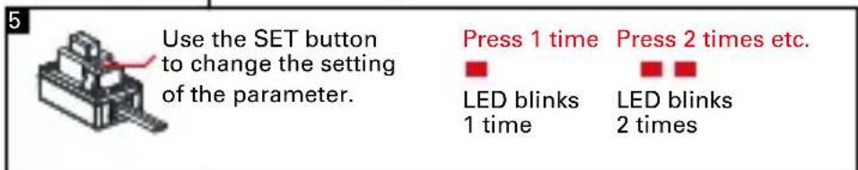
text_image
Use the SET button to change the setting of the parameter. Press 1 time LED blinks 1 time Press 2 times etc. LED blinks 2 times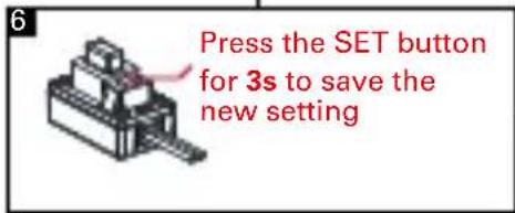
text_image
Press the SET button for 3s to save the new setting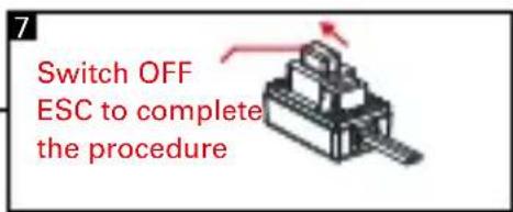
text_image
Switch OFF ESC to complete the procedureAVAILABLE AND DEFAULT SETTINGS
| Parameter | Setting | |||
| 1 2 3 4 | ||||
| 1. Running Mode | Forward with Brake | Forward/Reverse with Brake | ||
| 2. Low Voltage Cut-Off Threshold | No Cut-Off | 3.0V/Cell | 3.4V/Cell | |
| 3. Start Mode(Punch) Level1 | Level3 Level4 | |||
| 4. Max Brake Force 25% | 75% 100% | |||
| 5. Motor Rotation Direction | CCW | |||
BLACK = DEFAULT SETTING
More information on page 11-12-13
INSTRUCTION MANUAL · ENGLISH
Thank you for purchasing a Team Orion dDrive brushless power unit. This unique system combines the brushless motor and ESC inside a single aluminum case. Please read these instructions thoroughly before using your dDrive.
WARNINGS
Read the ENTIRE instruction manual to become familiar with the features of the product before operating. This is a sophisticated hobby product. It must be operated with caution and common sense and requires some basic mechanical ability. This product is not intended for use by children without direct adult supervision. Do not attempt disassembly, use with incompatible components or augment product in any way. This manual contains instructions for safety, operation and maintenance. It is essential to read and follow all the instructions and warnings in the manual, prior to assembly, setup or use, in order to operate correctly and avoid damage or serious injury.
- Use extra caution in case of water exposure
• Always use only compatible batteries.
• Always power off the dDrive when not in use.
• Always disconnect the battery when not in use. - The dDrive will become hot during use, be careful before touching or handling it.
Failure to exercise caution while using this product could result in product malfunction, electrical issues, excessive heat, FIRE, and ultimately injury and property damage.
Not for children under 14 years. This is not a toy.
LIMITED WARRANTY
Team Orion warrants to the original purchaser that the product purchased is free from defects in materials and workmanship at the date of purchase. Team Orion reserves the right to change or modify this warranty without notice and disclaims all other warranties, express or implied. This warranty is limited to the original purchaser and is not transferable. Replacement as provided under this warranty is the exclusive remedy of the purchaser. This warranty covers only the products purchased from an authorized dealer. Third party transactions are not covered by this warranty. Proof of purchase is required for warranty claims. Team Orion makes no warranty or representation, express or implied, about non infringement, merchantability or fitness for a particular purpose of the product. The purchaser acknowledges that they alone have determined that the product will suitably meet the requirements of the purchaser's intended use.
Team Orion's sole obligation hereunder shall be that it will, at its option, repair or replace any product determined by Team Orion to be defective in the event of a defect, this is the purchaser's exclusive remedy. Replacement decisions are at Team Orion's sole discretion. This warranty does not cover cosmetic damage or damage due to acts of God, accident, misuse, abuse, negligence, commercial use, or modification of or to any part of the product. This warranty does not cover damage due to improper installation, operation, maintenance or attempted repair by anyone. Team Orion will not be liable for special, indirect or consequential damages, loss of profits or production or
commercial loss in any way connected with the product, whether claim is based in contract, warranty, negligence, or strict liability. Further, in no event shall the liability of Team Orion exceed the individual price of the product on which liability is asserted. As Team Orion has no control over use, setup, final assembly, modification or misuse, no liability shall be assumed nor accepted for any resulting damage or injury. By the act of use, setup or assembly the user accepts all resulting liability. If you as the purchaser or user are not prepared to accept the liability associated with the use of this product, you are advised to return this product immediately in new and unused condition to the place of purchase.
Instructions for disposal of WEEE by users in the European Union
This product must not be disposed of with other waste. Instead, it is the user's responsibility to dispose of their waste equipment by handing it over to a designated collections point for the recycling of waste electrical and electronic equipment. The separate collection and recycling of your waste equipment at the time of disposal will help to conserve natural resources and ensure that it is recycled in a manner that protects human health and the environment. For more information about where you can drop off your waste equipment for recycling, please contact your local city office, your household waste disposal service or where you purchased the product.
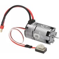
FEATURES
- Designed for on-road and off-road 1/10 scale cars
- Splash proof
- Forward and reverse function
• 4 pole brushless motor
• 45A ESC
• High power built-in BEC system - Easy set-up via the setup button located on the switch
- Adjustable parameters
- Multiple protection systems: battery low voltage cut-off, overheating, radio signal loss, stuck motor
INSTALLATION - CONNECTION
ATTACHMENT: Attach the dDrive to the car's motor mount using 3mm metric screws. If a motor was already fitted to your car, you will likely be able to re-use the same screws. Adjust the motor so that there is about 0.5mm play between the gear and pinion.
WARNING! If the motor screws are too long, you risk shorting and damaging the motor!
GEARING: You can use the original pinion that came with your car. However, you may also need to change the gearing to get optimal performance. If the dDrive overheats use a smaller pinion, if the car is slow and the motor temperature is low, you can use a bigger pinion to increase performance.
CONNECTION: The dDrive is equipped with a battery connector, a receiver plug and a power/setup switch. Connect the ESC receiver plug to the channel 2 of your receiver and secure the switch with double-sided tape to the car chassis.
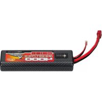
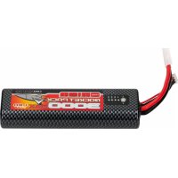
BATTERY: Use a 2S LiPo 7.4V (recommended) or 6-7 cell NiMH 7.2-8.4V battery as a power source. The battery must be equipped with a Deans® type connector compatible with the one installed on the ESC. Using low grade batteries, adapters or modifying the ESC connectors, can cause loss of performance, damage, or void the warranty.
ESC CALIBRATION
In order to ensure proper function, the ESC must be calibrated to your transmitter inputs. It is recommended to center the trims and reset all settings inside the transmitter before proceeding with the calibration. Follow the procedure below to calibrate your ESC
A. Switch off the ESC and switch the transmitter on,
B. Press and hold the SET button (located on the ESC's switch), then switch on the ESC. Release the SET button as soon as the red LED starts to flash.
C. Calibrate the throttle points by pressing the SET button once after each step.
- neutral point (1 green flash)
- full throttle (2 green flashes)
- full brakes/reverse (3 green flashes)
D. The motor will run 3 seconds after the last step is completed.
STATUS LED FUNCTION
• In the neutral position, no LED are lit.
- The red LED lights when the car is moving forward, backwards or when braking.
- At full throttle the green LED is lit.
AUDIO WARNING TONES
- Input voltage problem: ESC checks the input voltage as it is switched on, if a problem is detected, the ESC emits repeatedly two beeps with a 1 second pause and the green LED flashes simultaneously (xx-xx-xx).
- Radio signal problem: ESC checks the radio signal input as it is switched on, if a problem is detected, the ESC emits repeatedly a beep with a 2 second pause and the green LED flashes simultaneously (x-x-x).
ESC ADVANCED SETUP
You can adjust certain parameters by using the SET button located on the ESC's switch. To adjust the parameters, follow the procedure below.
A. Switch on the ESC.
B. Press the SET button and release it when the green LED starts flashing.
C. Use the SET button to cycle between the various adjustable parameters. The number of green flashes indicates the parameter, one flash = running mode, two flashes = low voltage cut-off and so on. The ESC will cycle through all the adjustable parameters in a loop.
D. Once the green LED is flashing the number of times
relative to the parameter you wish to modify, press the SET button until the red LED starts flashing, indicating the current setting for that parameter, one flash = setting one, two flashes = setting two, etc.
E. Press the SET button to change the current setting value, the ESC will cycle through all the available settings.
F. Once the red LED is flashing the number of times relative to the setting you wish to use, press the SET button for 3 seconds. The setting is saved.
G. Switch off the ESC to exit programming mode
ADJUSTABLE PARAMETERS
Running Mode
1) "Forward Only with Brake" this mode is meant for competition use. In this mode the car can go forward and brake, there is no reverse.
2) "Forward/Reverse with Brake" this is the basic all-around mode. In this mode the car can go forward and reverse and can also brake. When you move the throttle to the reverse position while the car is moving forward, brakes are applied until the car is fully stopped, reverse cannot engage while the car is moving. To engage reverse, once the car has stopped, release the brakes and move the throttle to the reverse position again. While braking or in reverse, if the throttle is moved to the forward position, the car will immediately accelerate forward.
Low Voltage Cut-off
This function helps to prevent battery over-discharge. The ESC continuously monitors the battery's voltage. If the voltage becomes lower than the threshold for 2 seconds, the output power is shut off and the red LED flashes twice repeatedly.
Start mode "punch"
This parameter sets the initial throttle punch when the car accelerates. Level1 gives a softer initial acceleration and level 9 gives a stronger initial acceleration.
Max brake force
This parameter adjusts the maximum breaking force. A higher value provides stronger braking but also makes the ESC to run hotter and may cause overheating issues.
Motor rotation direction
This parameter adjusts the motor rotation direction, counter clockwise (CCW, default) or clockwise (CW).
With the throttle in the neutral position, press and hold the SET button for 5 seconds, the red and green LED will flash simultaneously indicating that the parameters have been reset to the factory default values.
TROUBLESHOOTING
In case of malfunction, check the connections, settings and installation. Make sure that the batteries are also charged and functional.
NOTE: Using low power NiMH batteries can cause the dDrive to overheat and have low performance. Use of LiPo batteries is recommended.
Recommended working temperature: For optimal performance, adjust the gearing and ESC settings so that the outer case temperature is comprised between 60-80°C max (140-175°F max).
Overheating and/or stutter: Make sure that the car's transmission runs freely. Check the gearing, use a smaller opinion if necessary.
Low performance: Make sure that the car's transmission runs freely. Check the gearing, if the motor temperature is low, you can use a bigger pinion to increase performance.
Do not use the dDrive if the case, connectors or wires are damaged. Stop using the dDrive immediately if it overheats excessively, melts or emits smoke.
If you are unable to solve the issue, stop using the ESC and seek assistance from your local Team Orion reseller.
CONNEXIONS
| Parameter | Setting | |||
| 1 2 3 4 | ||||
| 1. Running Mode | Forward with Brake | Forward/Reverse with Brake | ||
| 2. Low Voltage Cut-Off Threshold | No Cut-Off | 3.0V/Cell | 3.4V/Cell | |
| 3. Start Mode(Punch) Level1 | Level3 Level4 | |||
| 4. Max Brake Force 25% | 75% 100% | |||
| 5. Motor Rotation Direction | CCW | |||
EN NOIR = VALEURS PAR DEFAULT
Start Mode "Punch" (acceleration)
Max Brake Force (puissance freinage)
natural_image
Pure mechanical component diagram without any text, numbers, or symbolsnatural_image
Pure mechanical assembly diagram without any text, numbers, or symbolsnatural_image
Simple line drawing of a mechanical tool or bracket (no text or symbols)2
natural_image
Diagram of a curved mechanical component with a red arrow indicating direction (no text or symbols)3

natural_image
Pure mechanical component diagram without any text, numbers, or symbolsm = 311
text_image
1 m drm = 311
text_image
1 drThe Ground Truth image displays a single, solid horizontal line. According to Rule 2 (UNDERSCORE & LINE RULES), this is a stylistic or background line, not a placeholder underscore. Therefore, the OCR result must ignore it and output nothing or only meaningful text. The provided OCR content is "____", which consists of four underscores. This is an incorrect interpretation of the line as a placeholder, violating the rule that stylistic lines must be ignored. The OCR has hallucinated underscores where none should exist based on the GT's visual context. Hence, the OCR result is inconsistent with the Ground Truth.
text_image
1 drLED
natural_image
Close-up of a cylindrical electronic device with red and green components, no visible text or symbolsLEDLED
natural_image
Close-up of a metallic cylindrical device with red and green components, possibly an electric motor or sensor (no visible text or symbols)■ ■ ■
natural_image
Close-up of a mechanical component with red and green markings (no visible text or symbols)| Parameter | Setting | |||
| 1 2 3 4 | ||||
| 1. Running Mode | Forward with Brake | Forward/Reverse with Brake | ||
| 2. Low Voltage Cut-Off Threshold | No Cut-Off | 3.0V/Cell | 3.4V/Cell | |
| 3. Start Mode(Punch) Level1 | Level3 Level4 | |||
| 4. Max Brake Force 25% | 75% 100% | |||
| 5. Motor Rotation Direction | CCW | |||
schwarz = Standardwert
Copyright Team Orion © 2015