Sand Rail - Remote control toy XciteRC - Free user manual and instructions
Find the device manual for free Sand Rail XciteRC in PDF.
| Product type | Radio-controlled toy |
| Brand | XciteRC |
| Model | Sand Rail |
| Dimensions (L x W x H) | 535 x 297 x 190 mm |
| Wheelbase | 340 mm |
| Weight | Approximately 2.9 kg |
| Motor | Brushless 2574 KV |
| ESC | 2-3S LiPo (7.4 - 11.1 V DC) |
| Transmitter | XRC 2i 2.4 GHz 2-channel |
| Transmitter range | Approximately 150 m |
| Transmitter power supply | 3 AA batteries or rechargeable batteries |
| Model power supply | LiPo battery included |
| Use | On suitable water surfaces, without obstacles |
| Recommended minimum age | 14 years |
| Package contents | RTR vehicle, transmitter, battery, charger, instruction manual |
| Safety instructions | Numerous, must be read carefully |
| Maintenance | Cleaning after each use, checking screws and cables |
| Spare parts | Available, references listed in the manual |
| Repairability | Yes, with original parts |
| Environmental protection | Follow recycling guidelines |
Frequently Asked Questions - Sand Rail XciteRC
User questions about Sand Rail XciteRC
0 question about this device. Answer the ones you know or ask your own.
Ask a new question about this device
Download the instructions for your Remote control toy in PDF format for free! Find your manual Sand Rail - XciteRC and take your electronic device back in hand. On this page are published all the documents necessary for the use of your device. Sand Rail by XciteRC.
USER MANUAL Sand Rail XciteRC
natural_image
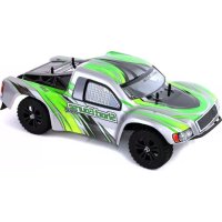
Exterior view of a blue XciteRC Sand Rail off-road vehicle (no signage or text beyond branding)30201000 Sand Rail Buggy 4WD Brushless blue

natural_image
Green and white XciteRC Sand Rail off-road vehicle with visible tires and suspension (no text or symbols on body)30202000 Sand Rail Buggy 4WD Brushless green
DE
Inhaltsverzeichnis
natural_image
Two black electronic devices with battery modules and charging leads, shown from top and bottom views (no text or symbols visible)text_image
Four-panel diagram showing a vehicle chassis with labeled components and control switches, including XRC21 2.4GHz display.natural_image
Close-up of a hand holding a small electronic device with a screen and control buttons (no visible text or symbols)
natural_image
Close-up of a hand holding a black electronic device with an arrow pointing to it, no visible text or symbols.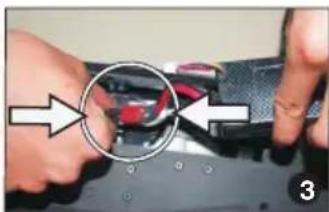
natural_image
Close-up of hands assembling a mechanical component with a magnified circular detail (no text or symbols visible)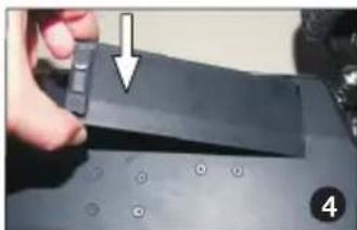
natural_image
Close-up of a hand holding a black electronic device with a white arrow pointing to it, no visible text or symbols.Inbetriebnahme
natural_image
Close-up of a vehicle chassis with a sensor and ON button indicator (no readable text or symbols)natural_image
Green and black off-road vehicle with visible tracks and suspension, labeled 'A' (no text or symbols on the vehicle itself)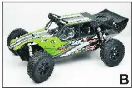
natural_image
Green and black off-road vehicle with visible tracks and suspension components (no text or symbols)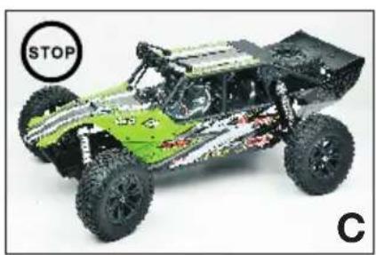
natural_image
Green and white toy car with visible suspension, labeled STOP and C (no text or symbols on the vehicle itself)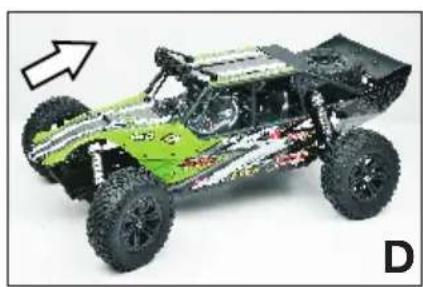
natural_image
Green and black off-road vehicle with visible tracks and suspension components, no text or symbols present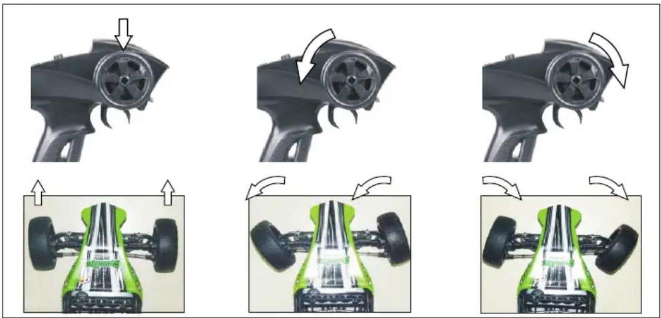
natural_image
Sequence of four images showing a car's internal components before and after motion, with arrows indicating changes (no text or symbols)natural_image
Two technical diagrams showing a stator knob and a green toy car with wheels, both without any text or symbols.
text_image
ST.D/R - +Nach der Fahrt
natural_image
Front view of a vehicle chassis with a circular sensor labeled 'OFF' (no other text or symbols visible)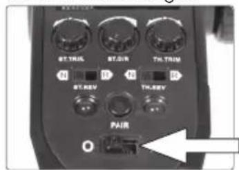
text_image
ST-TRUS ST-FLR TH-TRIM N N N ST-REV TH-REV PAIRnatural_image
Close-up of a red mechanical component with green connectors and orange wires, no visible text or symbols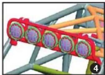
natural_image
Close-up of a red and green mechanical component with purple circular features, mounted on a gray frame (no visible text or symbols)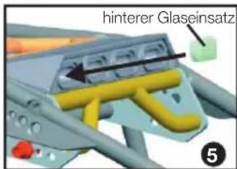
natural_image
3D model of a steel truss structure with yellow and purple components, no visible text or symbolsnatural_image
Pink plastic bag with three circular components and green star-like symbols below (no text or labels)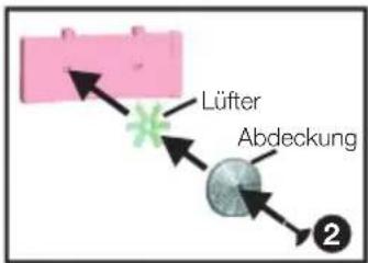
text_image
Lüfter Abdeckung 2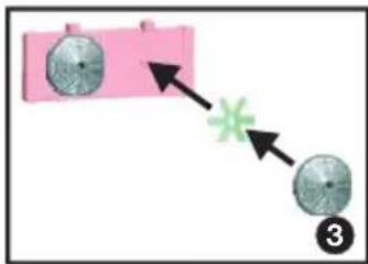
flowchart
graph TD
    A["Circle 1"] --> B["Green Star"]
    C["Circle 2"] --> B
    style A fill:#f9f,stroke:#333
    style B fill:#ccf,stroke:#333
natural_image
Pink plastic fan with two fans, no text or symbols visible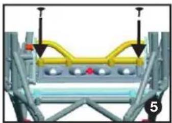
natural_image
Mechanical assembly diagram showing a yellow and gray component with mounting holes and a numbered label (5), no readable text or symbols present.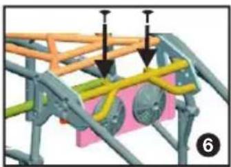
natural_image
3D mechanical assembly diagram showing structural components with arrows indicating assembly or force direction (no text or symbols)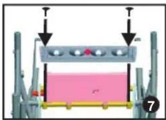
natural_image
Mechanical assembly diagram showing a piston-like component with arrows indicating force or movement (no text or symbols present)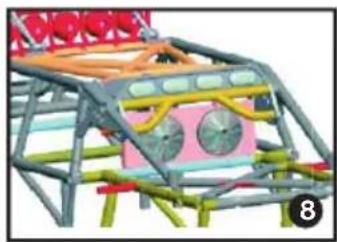
natural_image
3D model of a mechanical structure with colored components and no visible text or symbolsnatural_image
3D rendered model of a floating platform with mountain-like structures (no text or symbols)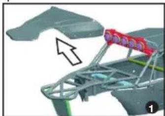
natural_image
3D model of a mechanical assembly with red components and an arrow indicating direction (no text or symbols)
natural_image
3D mechanical assembly diagram showing a bracketed component with an arrow pointing to a specific part (no text or symbols visible)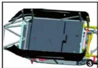
natural_image
3D rendering of a mechanical component with internal structure and mounting brackets (no visible text or symbols)DE
DE
natural_image
3D rendering of a vehicle chassis frame with metal framing and vertical supports (no visible text or symbols)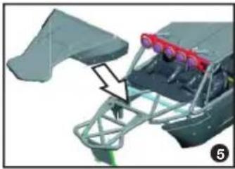
natural_image
3D mechanical assembly diagram showing a frame with red eyeglasses and a bracket (no text or symbols)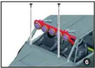
natural_image
Close-up of a red and gray aircraft fuselage with visible structural elements and mounting points (no text or symbols)Fehlersuche
chemical
Chemical structures of CdHgPb and Li-Po catalysts with labeled components- Cd = Cadmium
- Pb = Blei
• Hg = Quecksilber - Li = Lithium
DE
EN
Summary
Intended Usage 17
Scope of delivery....17
Required accessories 17
Explanation of Symbols 17
WARNINGS AND SAFETY NOTES 17
Handling precautions for batteries or rechargeable batteries....19
The remote control system 19
Transmitter 20
BINDING: 20
Charging the Battery: 21
Insert the battery 21
Getting started 21
After the ride: 23
Chassis Tuning Guide....23
Maintenance....24
Optional Parts Installation 24
Troubleshooting....25
Repairs, Spare parts 26
Specifications 27
Environmental Protection Notes 27
Notes on battery law 27
Declaration of conformity....51
Legal information
This manual is a publication of
All rights including translation, reproductions of any kind, such as photocopying, microfilming or storage in electronic data processing equipment, without the written permission of the publisher, reproduction in whole or part, is prohibited.
This manual corresponds to the technical status of the product at time of printing, changes in technology and equipment reserved. From the text and illustrations of this manual no claims can be derived.
NO LIABILITY FOR PRINTING ERROR! SUBJECT TO CHANGE!
The latest version of this manual can be found on the Internet at www.XciteRC.de
© Copyright 2013 by XciteRC-Modellbau GmbH & Co. KG
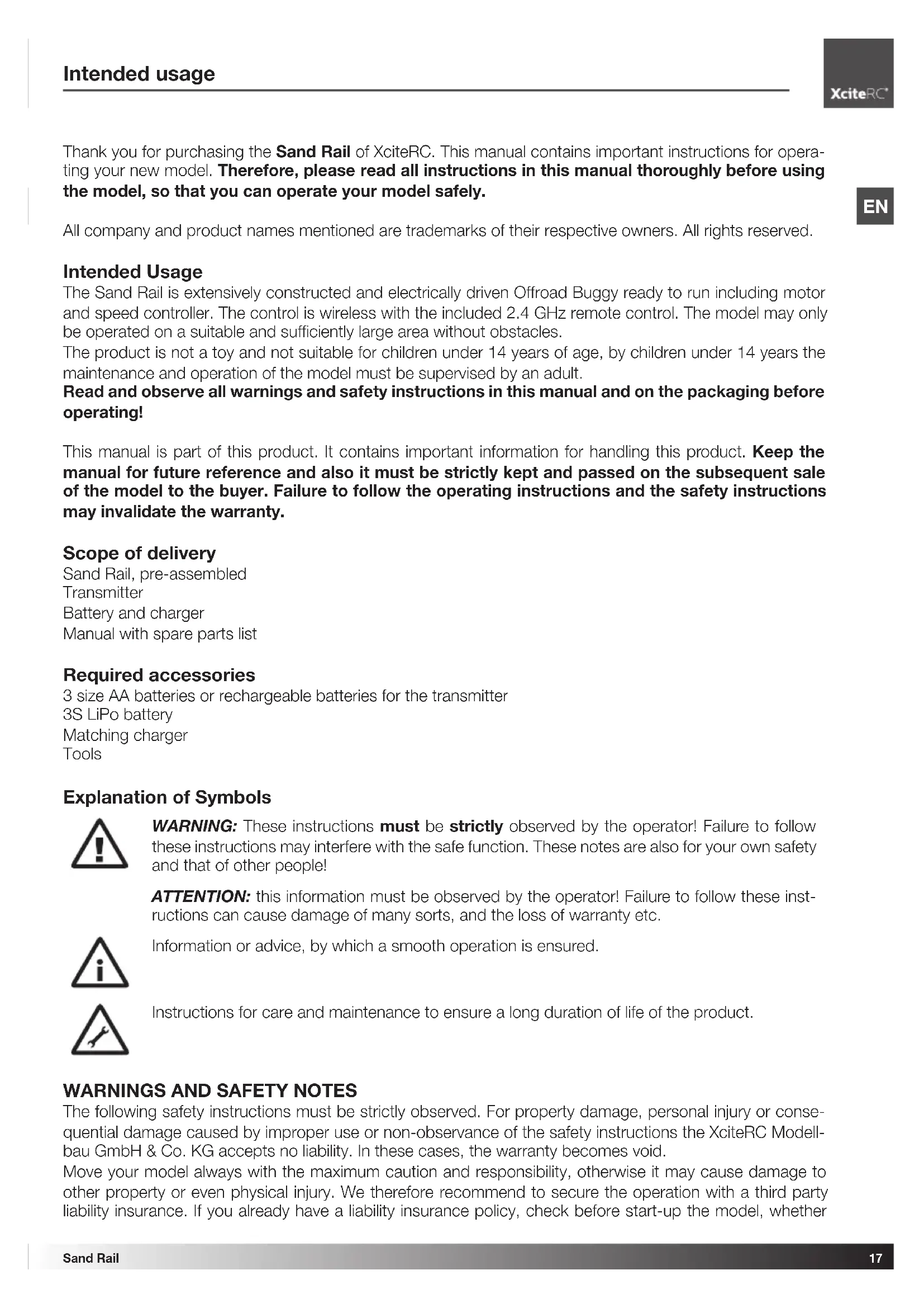
Thank you for purchasing the Sand Rail of XciteRC. This manual contains important instructions for operating your new model. Therefore, please read all instructions in this manual thoroughly before using the model, so that you can operate your model safely.
All company and product names mentioned are trademarks of their respective owners. All rights reserved.
Intended Usage
The Sand Rail is extensively constructed and electrically driven Offroad Buggy ready to run including motor and speed controller. The control is wireless with the included 2.4 GHz remote control. The model may only be operated on a suitable and sufficiently large area without obstacles.
The product is not a toy and not suitable for children under 14 years of age, by children under 14 years the maintenance and operation of the model must be supervised by an adult.
Read and observe all warnings and safety instructions in this manual and on the packaging before operating!
This manual is part of this product. It contains important information for handling this product. Keep the manual for future reference and also it must be strictly kept and passed on the subsequent sale of the model to the buyer. Failure to follow the operating instructions and the safety instructions may invalidate the warranty.
Scope of delivery
Sand Rail, pre-assembled
Transmitter
Battery and charger
Manual with spare parts list
Required accessories
3 size AA batteries or rechargeable batteries for the transmitter
3S LiPo battery
Matching charger
Tools
Explanation of Symbols

WARNING: These instructions must be strictly observed by the operator! Failure to follow these instructions may interfere with the safe function. These notes are also for your own safety and that of other people!
ATTENTION: this information must be observed by the operator! Failure to follow these instructions can cause damage of many sorts, and the loss of warranty etc.
Information or advice, by which a smooth operation is ensured.
Instructions for care and maintenance to ensure a long duration of life of the product.
WARNINGS AND SAFETY NOTES
The following safety instructions must be strictly observed. For property damage, personal injury or consequential damage caused by improper use or non-observance of the safety instructions the XciteRC Modellbau GmbH & Co. KG accepts no liability. In these cases, the warranty becomes void.
Move your model always with the maximum caution and responsibility, otherwise it may cause damage to other property or even physical injury. We therefore recommend to secure the operation with a third party liability insurance. If you already have a liability insurance policy, check before start-up the model, whether
radio-controlled models are covered by a corresponding amount.
EN

- The product contains small parts that can cause injury if swallowed, and must therefore be kept away from children under 3 years.
- The product is not a toy and not suitable for children under 14 years.
- The operation of radio-controlled models requires practice. In the beginning operate your new model therefore with extra caution and familiarize yourself with the response to your commands.
- ⚠️ WARNING: The safe operation requires concentration and quick reaction. Do not operate your model if you are tired or under the influence of drugs or alcohol – risk of accident and injury!
- ⚠️ WARNING: The control of this model is done via radio signals, which can be influenced by the environment. This may cause a suddenly loss of control of your model. Operate your model therefore only with sufficient light within line of sight and in an open area, away from cars, traffic and people – risk of accident and injury!
- Do not operate your model during a thunder storm or near radio towers or power lines.
- Radio remote controlled models may not be operated at any public space by implication (streets, roads, squares or lakes). Before operation please ask where the operation is allowed. This also applies to private property, here the consent of the owner is required.
- ⚠️ WARNING: Keep your fingers or loose clothing or hair away from the rotating parts or wheels - risk of injury!
- Always switch on the transmitter first, then the model. Ⓔ NOTE: during the operation of the transmitter must remain switched on!
- Never operate your model with low transmitter batteries, because this reduces the range of your model dramatically.
- If the drive battery is empty, the model first slow down until it no longer reacts properly to your commands. Stop the operation and change the drive battery or charge it again.
- Pay attention to the instructions and warnings for this and any other equipment used by you (chargers, rechargeable battery packs, etc.).
- ⚠️ WARNING: Keep packaging material, small parts, chemicals and electrical components away from children – risk of accident and injury!
- ⚠️ ATTENTION: Do not drive against obstacles that the model cannot overcome, and stay on full throttle. This can destroy the motor, speed controller or the transmission!
- The model and the transmitter may be neither get humid nor wet, especially the electronic components (receiver, speed controller, servo) and, if used, lithium batteries, are not waterproof! The model may not be used in the rain (or heavy fog), do not drive in wet grass or through puddles or snow.
- WARNING: Fire or explosion due to moisture in lithium batteries!
- Plastic parts (eg. suspension and body) is less flexible and can break more easily at cold temperatures (below 10^ C).
- The modification of the model is not permitted for safety and CE approval regulations, which applies in particular to the transmitter, receiver and speed controller. Maintenance or repairs using original replacement parts are excluded.
• After use, first turn off the model and then the transmitter.
- WARNING: remove the drive battery from the model and transmitter after use. Store the model never with built-in battery. Fire hazard!
- Store batteries separately on a non-combustible surface.
- The drive components (motor and speed controller) or the car battery may become hot during operation.
WARNING: Risk of burns! Let these components cool down completely after the operation (and also before each battery change)!
Operation of the model is performed solely at the risk of the operator. Only a careful and deliberate operation protects against physical injury and damage to property.
Handling precautions for batteries or rechargeable batteries
- Keep batteries away from children! Never let batteries unattended, as they can be swallowed by children or pets!
- Use only the recommended or equivalent type of batteries / rechargeable batteries.
- ⚠️ WARNING: do not expose batteries / rechargeable batteries to heat or throw into fire - fire or explosion hazard!
- WARNING: insert batteries / rechargeable batteries with the correct polarity, no short-circuiting - fire or explosion hazard!
- If possible, always replace all batteries at the same time, never use new and used batteries and batteries with different charge levels simultaneously.
- Do not use defective or damaged batteries or rechargeable batteries – fire hazard! Risk of chemical burns on contact with skin, use protective gloves!
- ⚠️ WARNING: Do not attempt to recharge non-rechargeable batteries in a charger - fire or explosion hazard!
- Remove the rechargeable batteries from the device before charging.
- Charging may take place only with a suitable charger for the type of battery on a fireproof surface and under constant adult supervision – fire hazard!
- Immediately remove used batteries from the devices.
NOTE: NiMH batteries must be checked at least every 3 months and, if necessary, recharged, otherwise because of the typic self-discharge they may get deep discharged and damaged! Therefore, better use so-called RTU batteries with a very low self-discharge.
- NOTE: note the specified storage voltage for lithium batteries. Is a completely full or empty lithium battery time stored for a longer time, it can be damaged.
The XciteRC Modellbau GmbH & Co. KG cannot monitor the proper use of the battery or batteries you use, therefore, the warranty is excluded due to incorrect charging or discharging.
The remote control system
Here you get an overview of the remote control system of your Sand Rail and its various features and settings. Before the first flight, you should have read and understood all these functions and settings.
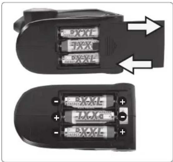
- Make sure that the transmitter is turned off - ON / OFF switch in position O.
- Now open the battery compartment cover on the bottom of the transmitter and insert three AA batteries (or rechargeable batteries) into the battery compartment of the transmitter. Pay attention to the correct polarity!
- Close the battery compartment cover and turn on transmitter – push ON / OFF switch in position I.
- Both LED's must lit (red and green). Ⓔ NOTE: If the green LED is flashing, the model may not be started – crash hazard! Change transmitter batteries immediately (or charge batteries).
- Pay attention to the LED's also during operation. If only the green LED flashes, stop driving as soon as possible. If both LED's flashing, stop immediately and replace transmitter batteries (or recharge the batteries).
natural_image
Two black electronic devices with battery modules and indicator lights, shown from top and bottom views (no text or symbols visible)EN
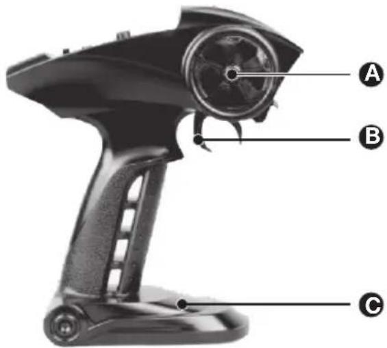
Transmitter
text_image
A B C
text_image
XciteRC XRC21 2.4GHz ST/REV ST/O/S TH/REV ST/REV TH/REV PLC 0 I ① ② ③ ④ ⑤ ⑥ ⑦ ⑧ ⑨A: Steering wheel: direction right or left
B: Throttle trigger: controls the speed and direction of the model
C: Battery compartment
-
Control trim: adjusts the straight ahead driving
-
Servoreverse steering
-
POWER LED: indicates the battery voltage
-
On / Off Switch: Turns the power of the transmitter ON / OFF
-
Steering Dual Rate: sets the maximum curve radius
-
Throttle trim: adjust the neutral position of the controller (always in the middle position!)
-
Servoreverse throttle
-
BIND-LED: indicates a "bound" receiver
-
BIND (pair)-button

NOTE: the adjuster for the throttle trim TH.TRIM and the servo reverse switches for steering ST.REV and throttle TH.REV must not be adjusted. So check the correct position before every ride: throttle trim to the center position (mark on the adjuster points up), steering reverse: switch in position N, servo reverse throttle: switch in position R.
BINDING:
The 2.4 GHz receiver of Sand Rail must be once „connected“ with a suitable transmitter, the so-called „binding“ procedure. This ensures that the receiver establishes a connection only with this transmitter and the model can be operated without interference. This process can be repeated any time.
The transmitter and receiver of the Sand Rail are already bound so that you can start flying immediately. Should a rebind gets necessary (eg. after a transmitter change), proceed as follows:
text_image
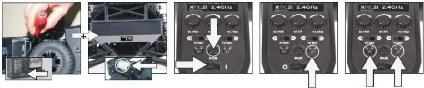
Diagram showing four different XRC21 2.4GHz remote control panel setups with labeled buttons and components.- Make sure that no other 2.4 GHz network (eg. WLAN or other transmitter) sends nearby.
- The distance between transmitter - Sand Rail should be maximum one meter.
- Press and hold the BIND button on the receiver (i.e. with a screwdriver) and turn ON the vehicle. Then
release the BIND button. Within 5 seconds press and hold the PAIR button on the transmitter and turn it on. The green LED starts flashing to indicate the binding process. After about 5 seconds, both LEDs light up continuously, the transmitter is now bound to the Sand Rail.
- To save a specific failsafe position, move the steering wheel or throttle trigger to the desired position (eg. brakes) and press the BIND button again after a successful binding procedure.
- If the model cannot be controlled, repeat the process.
Charging the Battery:
Before the first use of your new model the drive battery needs to be charged.
ATTENTION: Make sure to read all safety instructions regarding the use of rechargeable batteries. Also, if necessary, further safety instructions in the manual for your used charger.
WARNING: Charge may occur only with the supplied charger on a fireproof surface and under constant adult supervision - fire or explosion hazard!
For charging remove the battery from the vehicle.
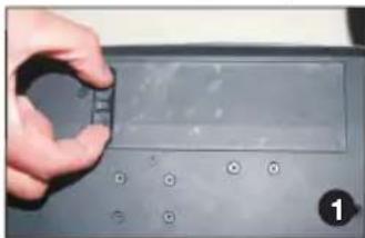
Insert the battery
natural_image
Close-up of a hand holding a small electronic device with a screen and control buttons (no visible text or symbols)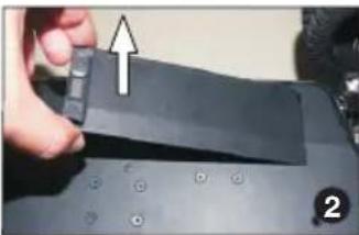
natural_image
Close-up of a hand holding a black electronic device with a white arrow pointing to it, no visible text or symbols.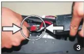
natural_image
Close-up of hands holding a device with a red component and circular annotation (no visible text or symbols)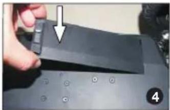
natural_image
Close-up of a hand holding a black electronic component with a white arrow pointing to it, no visible text or symbols.Getting started
Insert the battery into the vehicle and connect the plug to the ESC. Before you start, check all functions of the remote control. Does the vehicle follow exactly and directly your commands? Or does it react delayed or choppy? If yes, do not start anyway, but check transmitter and drive batteries and recharge or replace if necessary.
The run time of your Sand Rail depends on the surface. The maximum run time is reached on a straight and levelled surface. In hilly terrain or grass, the run time is much shorter, also the motor, speed controller and battery gets much warmer. If the battery is weak, the vehicle first gets slower until it finally stops completely. To increase the life time of the drive battery, you should cease operation when the vehicle begins to slow down.
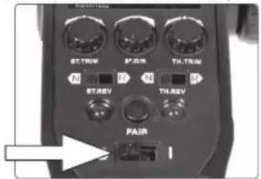
- Switch on the transmitter, ON/OFF-switch in position I.
text_image
STTRIM ST点位 THTRIM B1 R N B2 STREV THREV PAIR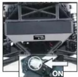
natural_image
Front view of a heavy-duty vehicle chassis with visible tracks and wheels, showing no text or symbols.-
Switch the vehicle ON. △ Note: wait about 5 sec. before you move the throttle trigger. This is needed to connect the transmitter with the reciever properly.
-
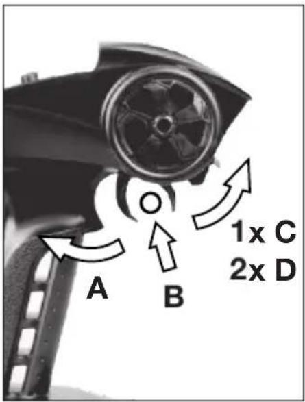
Drive:
EN
text_image
A B 1x C 2x D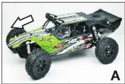
natural_image
Green and black off-road vehicle with visible suspension and tire tracks, labeled 'A' (no text or symbols on the vehicle itself)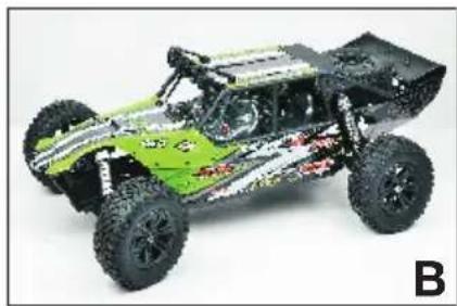
natural_image
Green and black off-road vehicle with visible tracks and suspension (no text or symbols)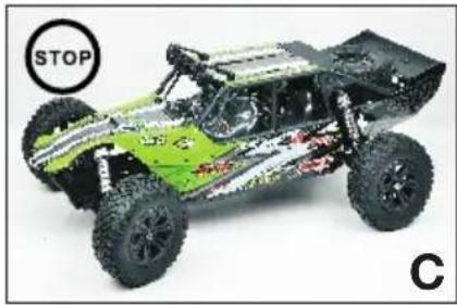
natural_image
Green and black off-road vehicle with visible tires and tracks, labeled 'STOP' and 'C' (no text on vehicle itself)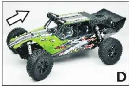
natural_image
Green and black off-road vehicle with visible tracks and suspension, shown in side profile (no text or symbols)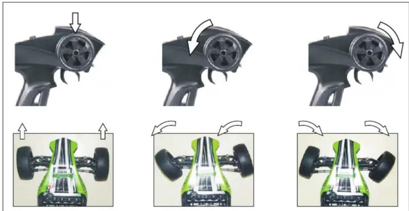
natural_image
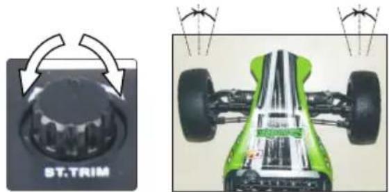
Sequence of five images showing a car's internal components and motion changes, including wheel rim, fan blade, and tire assembly (no text or symbols)- Steering trim: Drive slowly forward on level ground. Now check the straight ahead driving and adjust with the ST.TRIM knob if necessary.
natural_image
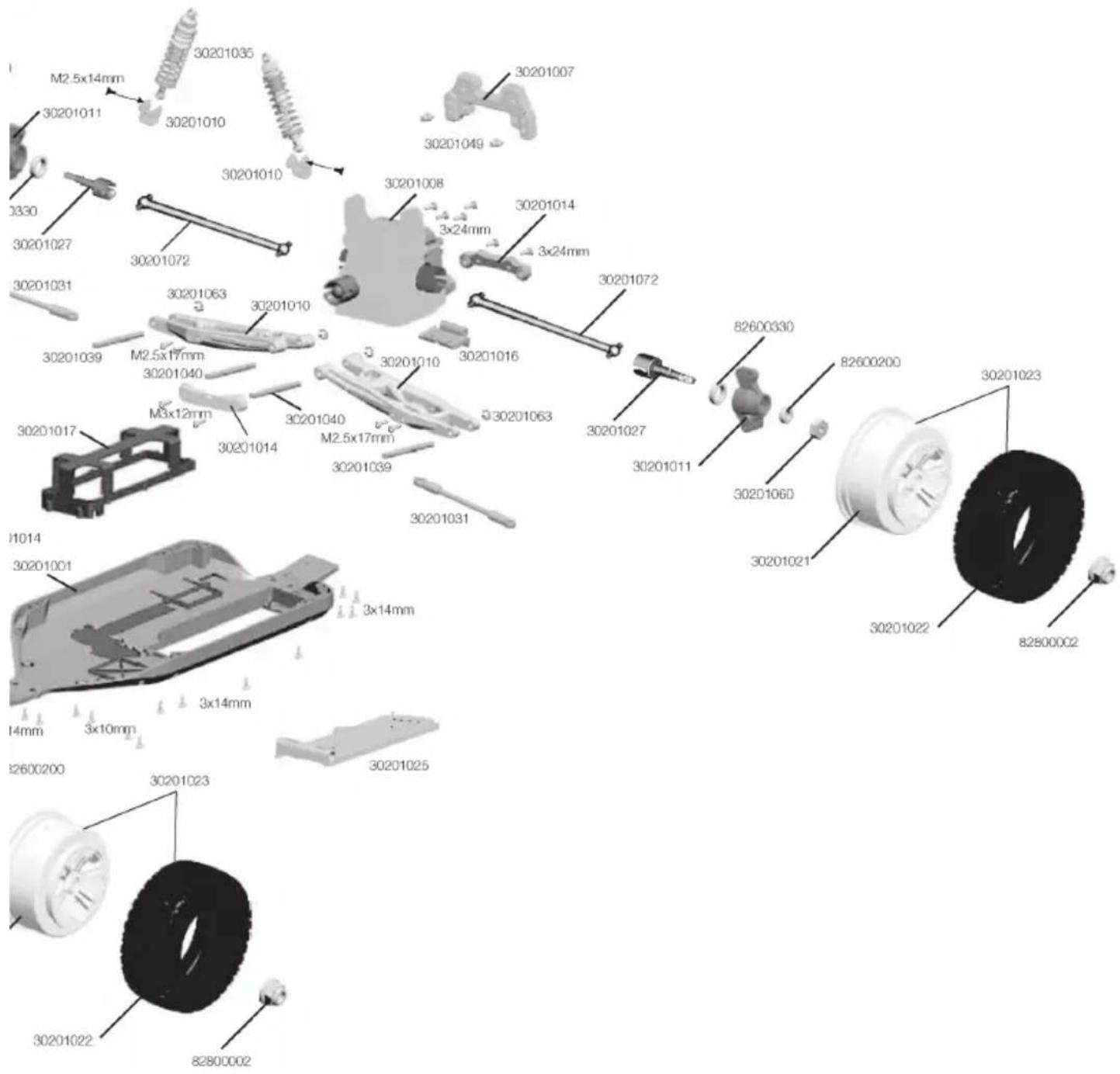
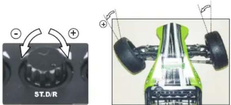
Two technical diagrams showing a car's front view and rear assembly, with no visible text or symbols.- Optimize steering: the maximum steering angle is adjusted with the ST.D/R knob. More maximum steering results in a tighter wall-to-wall turning circle, the vehicle turns in easier, but maybe a little nervous to drive. First turn the knob to the left - minimum steering angle. Now turn the steering wheel fully to the right (or left) and turn the adjusting knob ST.D/R slowly to the right until the desired steering angle is reached. You may do this setting also while running your vehicle. ⚠️ WARNING: do not turn too far, otherwise the
steering arm (30201011) press against the front uprights (30201012) which may damage the steering servo!
text_image
ST.D/R - +
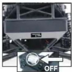
After the ride:
- Switch OFF the vehicle first, then the transmitter (ON/OFF-switch in position O).
natural_image
Front view of a vehicle chassis with visible tracks and wheels, marked with an 'OFF' button (no text or symbols on the vehicle itself)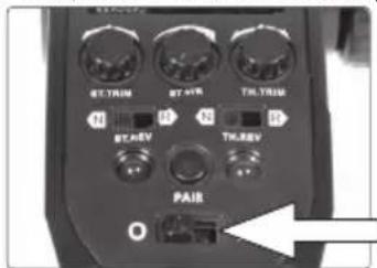
text_image
FTTRIM BT HR TH TRIM N B N R BT REV TH REV PAIB- ⚠️ WARNING: disconnect the drive battery and remove it from the model – fire hazard!
WARNING: the motor of the Sand Rail may get very hot during operation. Allow to cool down minimum 20 minutes before the next start to avoid damage. Fire hazard!
Chassis Tuning Guide
On your Sand Rail chassis two parameters can be adjusted: the toe of the front axle and the camber of both axles.

text_image
toe-out zero toe toe-in toe-in zero toe toe-out Front Turning Linkage Set Front Turning Linkage SetToe-in:
the setting is done via the steering linkage. More toe-in gives a better directional stability, but also poorer turn in at corner entry, and generally a less direct steering.
More toe-out effects a direct response to steering commands and more aggressivity at corner entry, but is also more difficult to control.
A neutral setting reduces tire wear and gives a neutral handling.
EN
text_image
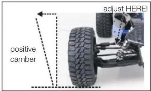
positive camber adjust HERE!Camber:
The tires should always have road contact with all the running tread. This is achieved with neutral or negative camber (about 2-3°) on both axes - more negative camber decreases the grip level again. Ideally, the camber is adjusted so that the tires wear is evenly.
Positive camber drastically reduces the grip and should, if at all, only be used on the front axle, to make the cornering less aggressive.
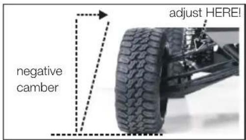
text_image
negative camber adjust HERE!Maintenance
To have fun with your model over a long period, occasional service work is required to get your model in good condition and to minimize wear.
- Remove dirt or dust depending with compressed air or a soft brush after each use. For stubborn dirt, a harder brush or a toothbrush can be used.
- To clean the body/fuselage no chemical cleaners such as thinners may used, as this damage the plastic of the body/fuselage. Normally a piece of soft cloth is ok, stubborn dirt can be removed with washing-up liquid.
- Check the tightness of all screws and tighten if necessary.
- Also check all connections, cables and power battery / rechargeable battery for damage.
- WARNING: Damaged batteries or rechargeable batteries must not be used again and must be disposed of immediately – fire hazard! Please note the disposal notes at the end of this manual.
- Check the model for worn, broken or jammed parts and gears and repair if necessary.
- ⚠️ WARNING: remove the batteries / rechargeable batteries of the transmitter and model when not in use – fire hazard!
Optional Parts Installation
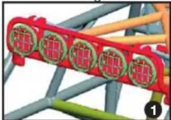
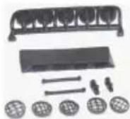
Offroad headlights Order No. 30201057
natural_image
Red industrial conveyor belt with green circular components, mounted on a metal frame (no visible text or symbols)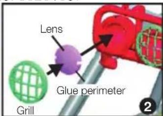
text_image
Lens Glue perimeter Grill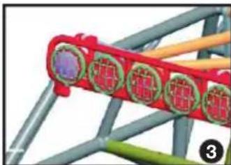
natural_image
Close-up of a red mechanical component with green and purple parts, mounted on a gray frame (no visible text or symbols)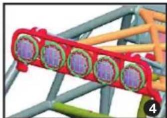
natural_image
3D rendered mechanical component with purple and green components, no visible text or symbols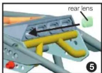
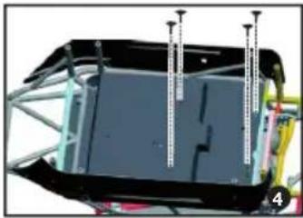
text_image
rear lens 5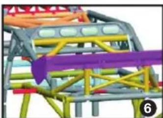
natural_image
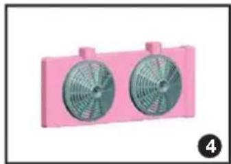
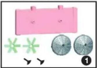
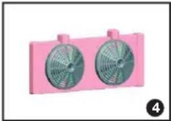
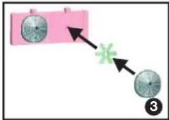
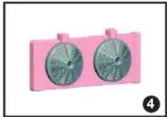
3D structural model of a truss structure with colored beams and a purple arrow indicating direction (no text or symbols)Radiator Order No. 30201019
natural_image
Pink plastic bag with three green star-shaped graphics and three meshed circular objects, no text or symbols present.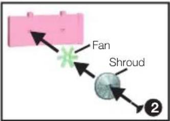
text_image
Fan Shroud ②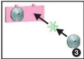
flowchart
graph TD
    A["Circle 1"] --> B["Star"]
    C["Circle 2"] --> B
    B --> D["Circle 3"]
natural_image
Two pink industrial fans with green blades, no text or symbols visible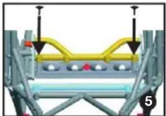
natural_image
Mechanical assembly diagram showing a frame with yellow and gray components and mounting brackets (no text or symbols)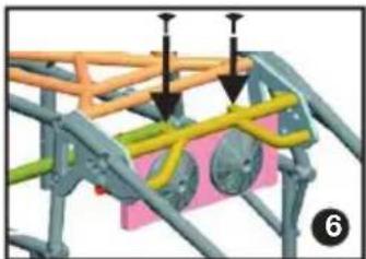
natural_image
3D mechanical assembly diagram showing structural components with arrows indicating force or movement (no text or symbols)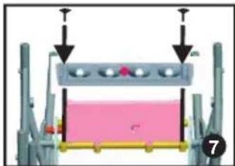
natural_image
Mechanical assembly diagram showing a clamping device with mounting holes and a pink component (no text or symbols)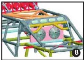
natural_image
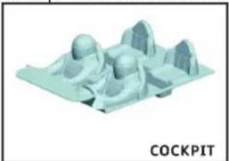
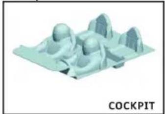
3D rendering of a mechanical structure with colored components and no visible text or symbolsCockpit Order No. 30201071
natural_image
3D rendered model of a floating platform with mountain-like structures (no text or symbols)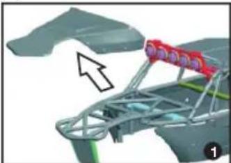
natural_image
3D rendering of a mechanical assembly with a red component and an arrow indicating direction (no text or symbols)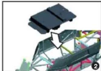
natural_image
3D mechanical component with highlighted section and arrow, no visible text or symbols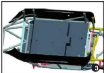
natural_image
Exterior view of a mechanical assembly with metal frame and mounting bracket (no visible text or symbols)
natural_image
3D mechanical assembly diagram showing a component with mounting brackets and structural elements (no visible text or symbols)
natural_image
3D mechanical assembly diagram showing a frame with a red visor and a wire cage, no visible text or symbols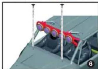
natural_image
Close-up of a military aircraft cockpit with red targeting systems mounted on the roof (no visible text or symbols)Troubleshooting
| Problem Possible | Cause Solution | |
| Motor does not run | Motor cable unplugged or brokenDrive battery emptyThrottle trim TH.TRIM on the transmitter set incorrectlyMotor broken | Insert the motor cable or solderChange or charge the batteryCheck transmitter, set trim correctlyReplace the motor |
| Vehicle runs backwards | Throttle servo reverse switch TH.REV in R position | Set servo reverse switch in position N |
| Weak motor / no power | Battery is almost emptyThrottle trim TH.TRIM on the transmitter set incorrectlyDrive train does not run smoothlyVehicle is very loudMotor gets very hot | Change or charge the batteryCheck transmitter, set trim correctlyCheck drive train and clean if necessaryCheck pinion clearance, adjust if necessaryAllow motor to cool; check drive train for binding parts and precise gear mesh |
EN
| Problem Possible | Cause Solution | |
| Vehicle is hard to control | Transmitter LEDs flashing - transmitter batteries almost emptySteering trim ST.TRIM on the transmitter set incorrectlyInterferenceThrottle trim TH.TRIM on the transmitter set incorrectly | Change or charge the batteryCheck transmitter, set trim correctlyTurn off the vehicle and transmitter, make a quick break and then re-trySet throttle trim to the center position |
| Vehicle has no function | LEDs on the transmitter does not light upTransmitter - receiver not boundInterferenceThrottle trim TH.TRIM on the transmitter set incorrectlyCar aerial torn offTransmitter LEDs flashing - transmitter batteries almost emptyDrive battery empty | Check that vehicle and transmitter are turned onRebind transmitter - receiver (see chapter BINDING)Set throttle trim to the center positionRepair antenna (vehicle)Change or charge the batteryChange or charge the battery |
| Vehicle runs very loud | Gear mash between the pinion and main gear set incorrectlyWorn gearsBearings runs tight or worn out | Check gear mesh adjust if necessaryCheck and replace if necessaryCheck and lubricate or replace if necessary |
Repairs, Spare parts
Normal wear and defective parts that result from an accident, are excluded from the warranty. These include in particular:
for car models: bald tires, worn parts and drive gears, or bent / broken suspension, chassis or bodywork ship models: damaged or broken propellers, torn superstructure
airplanes: damage due to improper transport or crash
If you find a part that is defective in material or workmanship right after opening the package, return - before you used it – to your dealer or directly to us and we will send you a replacement.
For the Sand Rail all parts are available as spares. If a part is defective or worn, you can identify it with the help of the exploded view, and the installation guide on pages 48 to 50 shows the correct installation.
In case of problems or questions, please contact your dealer or:
XciteRC Modellbau GmbH & Co. KG - Service, Autenbachstrasse 12, D-73035 Göppingen, Phone +49 7161 40 799 50
Email: service@xciterc.de
Spare parts for the Sand Rail you may order in your local hobby shop or online at http://www.XciteRC.de
Specifications
| Length 535 mm | |
| Width 297 mm | |
| Height 190 mm | |
| Wheel Base 340 mm | |
| Weight approx. 2.9 kg | |
| Motor Brushless 2574 KV | |
| ESC 2-3 S LiPo (7.4 - 11.1 V DC) | |
| Transmitter XRC 2i 2.4 GHz 2-channel | |
| Transmitter range approx. 150 m |
EN
Environmental Protection Notes
The symbol of the crossed out dust bin on the product or packaging indicates that this product must be disposed of separately from normal household waste. In order to avoid harmful effects on the environment and human health in the disposal of electrical and electronic equipment and the re-use or recycling are possible. You have the opportunity to submit electrical and electronic
equipment free of charge at an appropriate collecting point in your area. Please check with your city or town across the available depot. You also have the option to return old electrical and electronic equipment which has been purchased from us. We will then perform a proper recycling or reuse.
Possibly contained batteries must be removed from the product and disposed of at the appropriate collecting point.
Notes on battery law
According to the German Battery Act (BattG) the one who sells batteries (and accumulators etc.) or devices containing batteries, we are obliged to draw your attention to the following:
Batteries and rechargeable batteries should not be disposed of with household waste but you are legally obliged to return used batteries. Batteries can contain contaminants that could harm the environment or your health if improperly stored or disposed of. Batteries also contain important raw materials such as iron, zinc, manganese or nickel and can be recycled.
You can send us back the batteries after use either sufficient postage:
returned free of charge or in close proximity (eg in trade or municipal collection). The levy is limited to points of sale to end-users for the disposal of such waste batteries and customary amounts, which the distributor as new batteries in his range or has done.
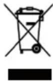
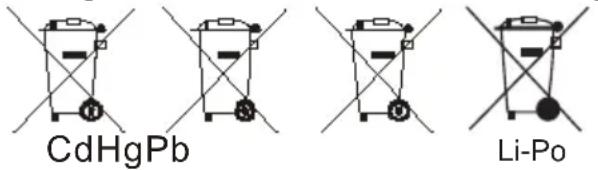
Batteries containing pollutants are marked with a sign, a crossed-out rubbish bin, and the chemical symbol of the pollutant-heavy metal.
This crossed-out bin means that you must not dispose of batteries with household waste.
Among these characters, see also the following symbols have the following meanings:
chemical
Chemical structures of CdHgPb and Li-Po catalysts with labeled components- Cd = cadmium
- Pb = plumbium
- Hg = mercury
- Li = lithium
FR
Sommaire
natural_image
Two black electronic devices with battery modules and indicator lights, showing internal structure and arrows indicating direction (no text or symbols on main body)text_image
Diagram showing four different XRC21 2.4GHz audio recording devices with labeled buttons and components, including a hand operating the tire.natural_image
Hand holding a digital device with control buttons and a screen (no visible text or symbols)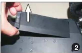
natural_image
Close-up of a hand pressing down on a black electronic device component (no visible text or symbols)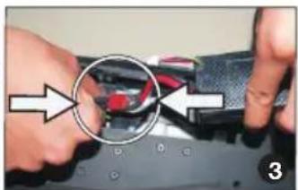
natural_image
Close-up of hands holding a small electronic device with a magnified circular detail (no visible text or symbols)
natural_image
Close-up of a hand holding a black electronic device with a white arrow pointing to it, on a keyboard (no visible text or symbols)FR
Mise en service
natural_image
Green and black off-road vehicle with visible tracks and suspension, labeled 'A' (no text or symbols on the vehicle itself)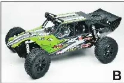
natural_image
Green and silver off-road vehicle with visible tires and suspension (no text or symbols)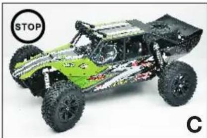
natural_image
Green and silver off-road vehicle with visible tires and tracks, labeled STOP and C (no text or symbols on the vehicle itself)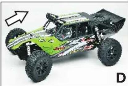
natural_image
Green and black off-road vehicle with visible tracks and suspension, shown in side profile (no text or symbols)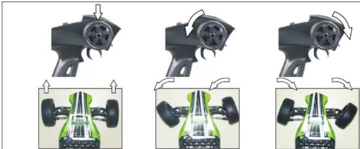
natural_image
Three sequential images showing a car's engine components with arrows indicating motion, including front and side views (no text or symbols)natural_image
Two technical diagrams showing a car body with a 'ST.TRIM' logo and its side profile view (no text or symbols on the diagram itself)
text_image
ST.D/R - +Apres l'utilisation
natural_image
Close-up of a vehicle's front suspension frame with a circular inset showing a sensor or sensor device (no visible text or symbols)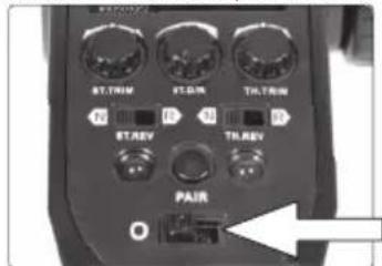
text_image
STTRIM STOR THTRIM N STREV TRREV PAIRnatural_image
Red industrial conveyor belt with green circular components, mounted on a metal frame (no visible text or symbols)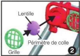
natural_image
Close-up of a red mechanical component with circular features, mounted on a gray metal frame (no visible text or symbols)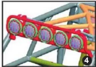
natural_image
3D diagram of a mechanical assembly with colored components and no visible text or symbols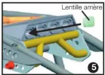
text_image
Lentille arrière ⑤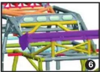
natural_image
3D model of a mechanical structure with colored components and a purple arrow indicating motion (no text or symbols)natural_image
Pink plastic bag with three green star-like symbols and three metallic circular components, no text or labels present.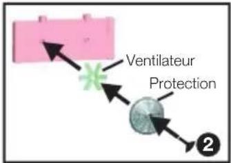
flowchart
graph TD
    A["Ventilateur Protection"] --> B["Process Unit"]
    B --> C["Final Product"]
flowchart
graph TD
    A["Pink Box with two circles"] --> B["Green Star Symbol"]
    B --> C["Black Circle"]
natural_image
Two pink plastic fans with green blades, no text or symbols visible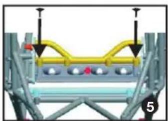
natural_image
Mechanical assembly diagram showing a frame with yellow and gray components and mounting points (no text or symbols)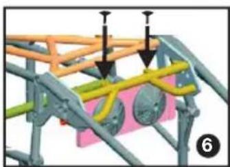
natural_image
3D structural diagram of a mechanical framework with colored components and arrows indicating assembly or movement (no text or symbols)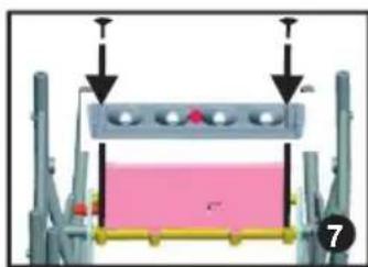
natural_image
Mechanical assembly diagram showing a piston-like component with two arrows pointing to its top and bottom (no text or symbols present)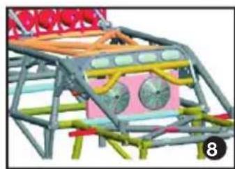
natural_image
3D rendered model of a mechanical structure with colored components and no visible text or symbolsCockpit Réf. 30201071
natural_image
3D rendered model of a floating platform with mountain-like structures (no text or symbols)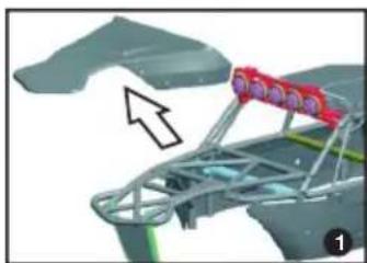
natural_image
3D mechanical assembly diagram showing a bracket with red components and an arrow indicating direction (no text or symbols)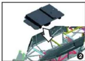
natural_image
Close-up of a mechanical assembly with a black component and a white arrow pointing to a component (no visible text or symbols)
natural_image
3D rendering of a rectangular mechanical component with internal structure and mounting brackets (no visible text or symbols)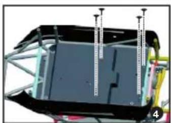
natural_image
3D mechanical assembly diagram showing a frame with metal framework and vertical fasteners (no text or symbols)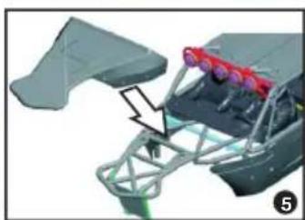
natural_image
3D mechanical assembly diagram showing a frame with red spray sensors and a black arrow indicating motion (no text or symbols)
natural_image
3D rendering of a mechanical assembly with red components and purple connectors (no visible text or symbols)natural_image
Exterior view of a black plastic mechanical component (no text or symbols visible)natural_image
Abstract geometric line drawing with intersecting lines and shapes (no text or symbols)natural_image
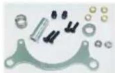
3D rendering of a mechanical component with two small parts, no visible text or symbolsAkkuhalter + Reglermontageplatte Battery Guard + ESC Bottom Mount Support accu + variateur
30201018
natural_image
Metal automotive bracket components including wheel, handle, and bracket (no text or symbols visible)Motorhalterung komplett Motor Mount complete Fixation moteur complète
30201029
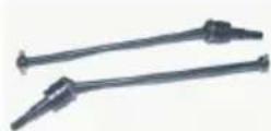
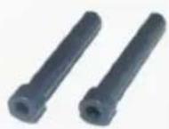
CVD-Antriebswellen vorne (2) Front CVD Drive Shafts (2) Arbre de transmission CVD avant (2)
30201030
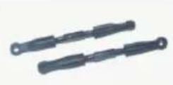
Vordere obere Querlenker (2) Front Upper Suspension Arms (2) Bras avant supérieur (2)
30201031
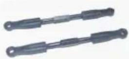
Hintere obere Querlenker (2) Rear Upper Suspension Arms (2) Bras arrière supérieur (2)
30201032
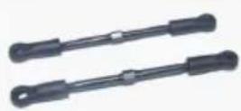
Spurstangen (2) Steering Linkage Set (2) Bielles de direction (2)
30201033
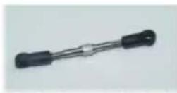
Servostange Servo Linkage Triangle servo - renvoi
30201034
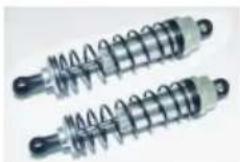
Alum. Öldruckstoßdämpfer vorne (2) Front Alum. Oil-filled Shocks (2) Amortisseurs alum. avant (2)
30201035
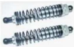
natural_image
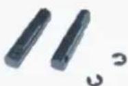
Two coiled industrial springs with metallic end caps (no text or symbols visible)Alum. Öldruckstoßdämpfer hinten (2) Rear Alum. Oil-filled Shocks (2) Amortisseurs alum. arrière (2)
30201036

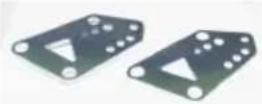
Unterfahrschutz vorne Aluminium Alum. Front Skid Plate Dispositif de protection anti- encastrement alum. avant
30201037
Hintere obere Dämpferhalterung (2) Rear Shock Upper Retainer (2) Fixation d'amortisseurs arrière en haut
30201038
Welle für Kegelrad vo./hi. + E-Clip Diff. Shafts FR/RR + E-Clip Arbre pour pignon conique avant/ arrière + E-Clip
30201039
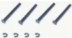
Untere Querlenkerstifte aussen (4) Lower Outer Hinge Pins (4) Goupille bras extérieur (4)
30201040
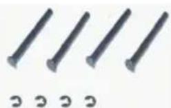
Untere Querlenkerstifte innen (4) Lower Inner Hinge Pins (4) Goupille bras intérieur (4)
30201041
Servo Saver Metallteile + Ackermanplatte Servo Saver Metal Parts + Ackerman Plate Servo Saver pièces de metal + plaque Ackerman
30201042
Lenkungsbolzen (2) Steering Posts (2) Support direction (2)
30201043
Differenzialausgänge vo./hi. (2) Diff. Outdrives FR/RR (2) Sortie de diff. avant/arrière (2)
30201044
Mitnehmer Mittelantriebswellen (2) Center Outdrives (2) Coupler arbre de transm. centre (2)
30201045
Steering Knuckle Bushings (8)
Steering Bushings 4x6x2.5mm (8)
text_image
2'10mm 2.5"22mm 8'6.8"1.3mm 5'17'9.3mm 2.5"10'0.3mmDiff. complete FR/RR w/o bevel gears
Diff. complete FR/RR
Pinion 13T (5mm shaft)
Pignon 13D (arbre 5mm)
82000320
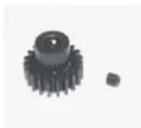
Ritzel 20 Z. (5mm Welle)
Pinion 20T (5mm shaft)
Pignon 20D (arbre 5mm)
61300001

Brushless Motor (2600KV) Brushless Motor (2600KV) Moteur brushless (2600KV)
55000010
natural_image
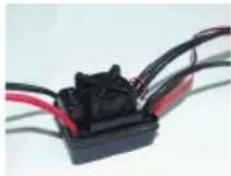
Close-up of a black electrical connector with red and black wires, no visible text or symbolsElektr. Fahrtenregler brushless 60A Brushless ESC 60A Variateur Brushless 60A
30201057
natural_image
Collection of simple circular and rectangular shapes on a plain background (no text or symbols)natural_image
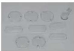
Abstract graphic with blue and black brushstroke patterns forming a stylized shape (no text or symbols)Karosserieteile blau + Decals Body assembly blue + Decals Carrosserie bleu + autocollantes
30201059
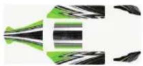
Karosserieteile grün + Decals Body assembly green + Decals Carrosserie vert + autocollantes
30201060
natural_image
3D rendered abstract geometric shapes with no text or symbolsMicro-LiPo-Charger 2-3S Micro-LiPo-Charger 2-3S Micro-LiPo-Charger 2-3S
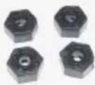
Karosserie abnehmen
Remove body
Enlever carrosserie
Torx

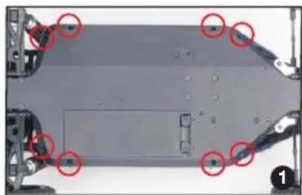
natural_image
Top-down view of a mechanical component with red circles highlighting specific areas (no text or symbols visible)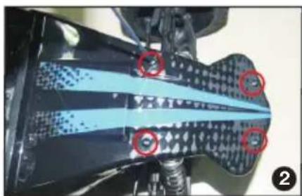
natural_image
Close-up of a mechanical component with blue and black patterned sections, marked by red circles (no visible text or symbols)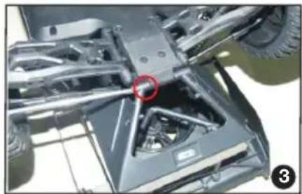
natural_image
Close-up of a vehicle chassis frame with visible structural components and a red circle highlighting a specific part (no text or symbols)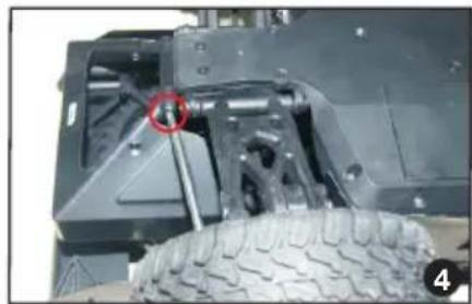
natural_image
Close-up of a vehicle's wheel assembly with a red circle highlighting a specific component (no visible text or symbols)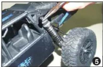
natural_image
Close-up of a hand using a tool to adjust the tire and nut assembly on a black vehicle (no visible text or symbols)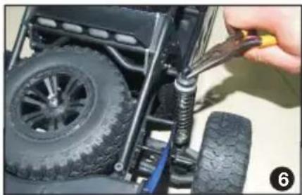
natural_image
Close-up of a hand adjusting a tire assembly with a tool, no visible text or symbols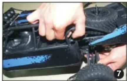
natural_image
Close-up of hands assembling a black and blue electric vehicle chassis (no visible text or symbols)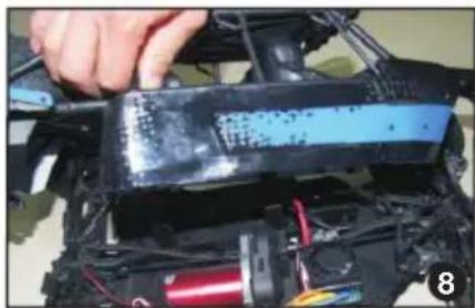
natural_image
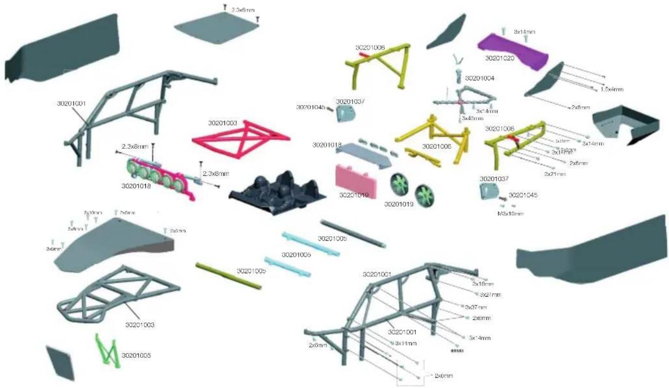
Close-up of a hand installing or adjusting a blue plastic component on a black vehicle chassis (no visible text or symbols)Montage Überrollkäfig · Roll Cage Assembly · Montage cage de protection
text_image
30201001 2.5x8mm 30201003 2.3x8mm 30201018 2.3x8mm 30201045 30201037 30201018 30201019 30201019 30201005 30201006 30201004 3x-4mm 3x45mm 30201006 3x14mm 3x14mm 3x14mm 3x14mm 3x14mm 3x21mm 3x21mm 3x21mm 3x21mm N3x10mm 3x18mm 3x27mm 2x6mm 3x-4mm 3x-4mm 3x-4mm 3x-4mm 3x-4mm 3x-4mm 3x-4mm 3x-4mm 3x-4mm 3x-4mm 3x-4mm 3x-4mm 3x-4mm 3x-4mm 3x-4mm 3x-4mm 3x-4mm 3X-6mm 3X-6mm 3X-6mm 3X-6mm 3X-6mm 3X-6mm 3X-6mm 3X-6mm 3X-6mm 3X-6mm 3X-6mm 3X-6mm 3X-6mm 3X-6mm 3X-6mm 3X-6mm 3X-6mm 3C-6mm 3C-6mm 3C-6mm 3C-6mm 3C-6mm 3C-6mm 3C-6mm 3C-6mm 3C-6mm 3C-6mm 3C-6mm 3C-6mm 3C-6mm 3C-6mm 3C-6mm 3C-6mm 3C-6mm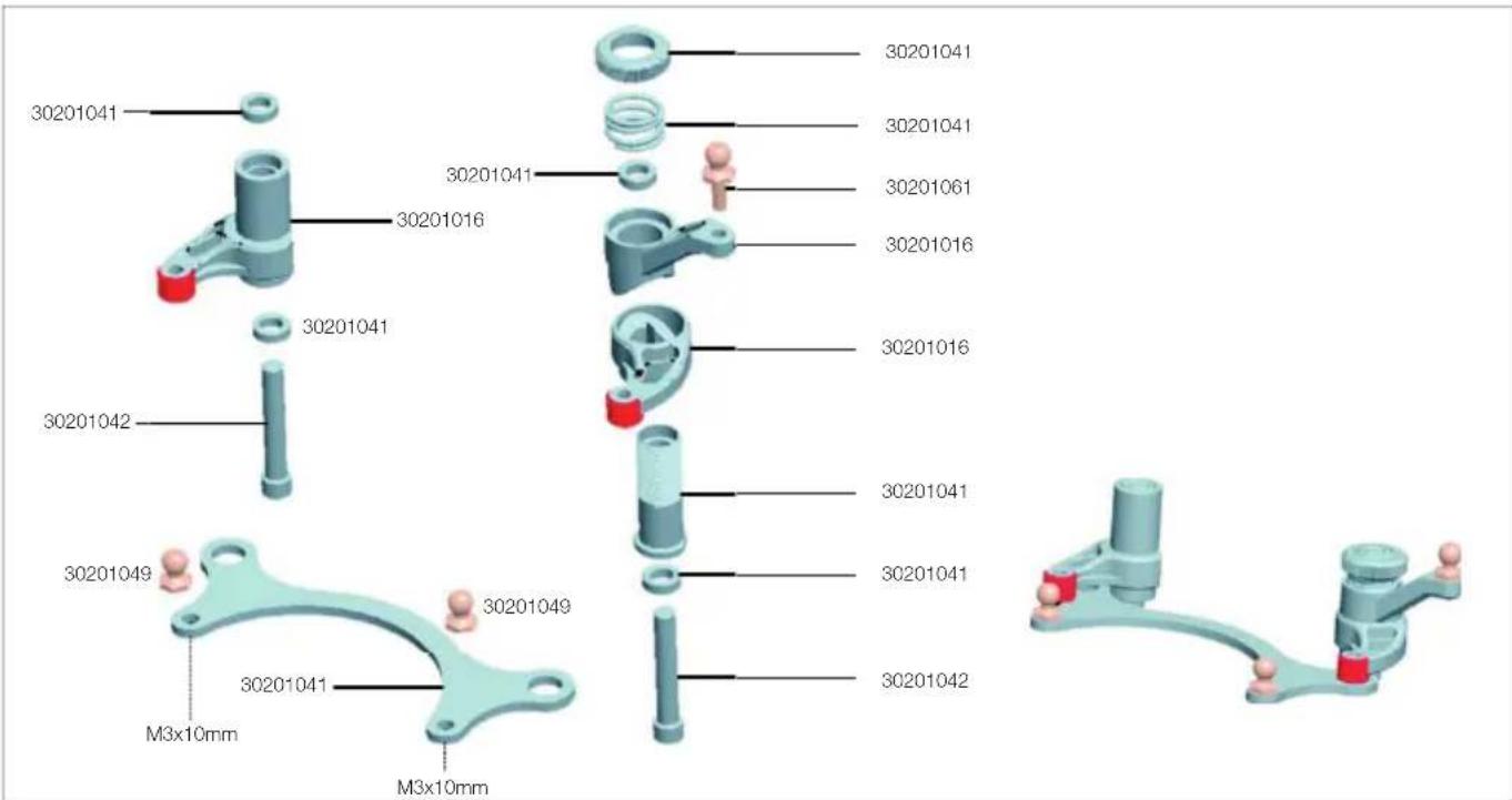
text_image
30201041 30201041 30201041 30201061 30201016 30201041 30201042 30201049 30201049 30201041 M3x10mm M3x10mm 30201041 30201041 30201041 30201042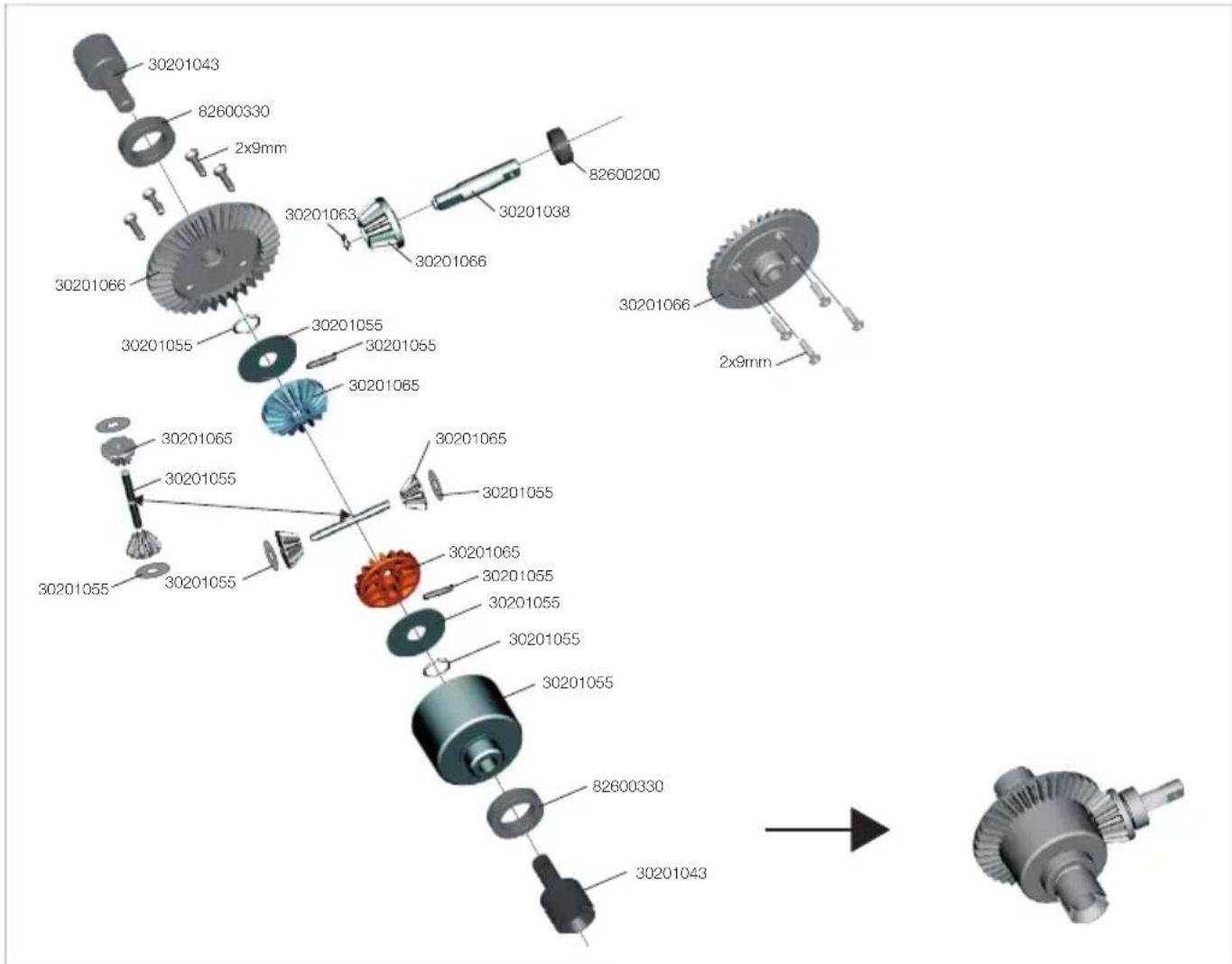
text_image
30201043 82600330 2x9mm 30201066 30201055 30201055 30201055 30201065 30201063 30201066 30201038 82600200 30201066 30201065 30201055 30201055 30201065 30201065 30201055 30201065 30201055 30201055 30201055 30201055 30201055 82600330 30201043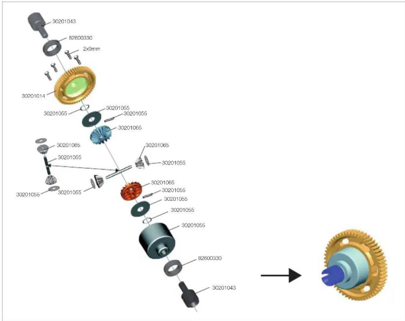
text_image
30201043 82600330 2x9mm 30201014 30201055 30201055 30201055 30201065 30201065 30201055 30201065 30201055 30201065 30201055 30201065 30201055 30201055 30201055 30201055 82600330 30201043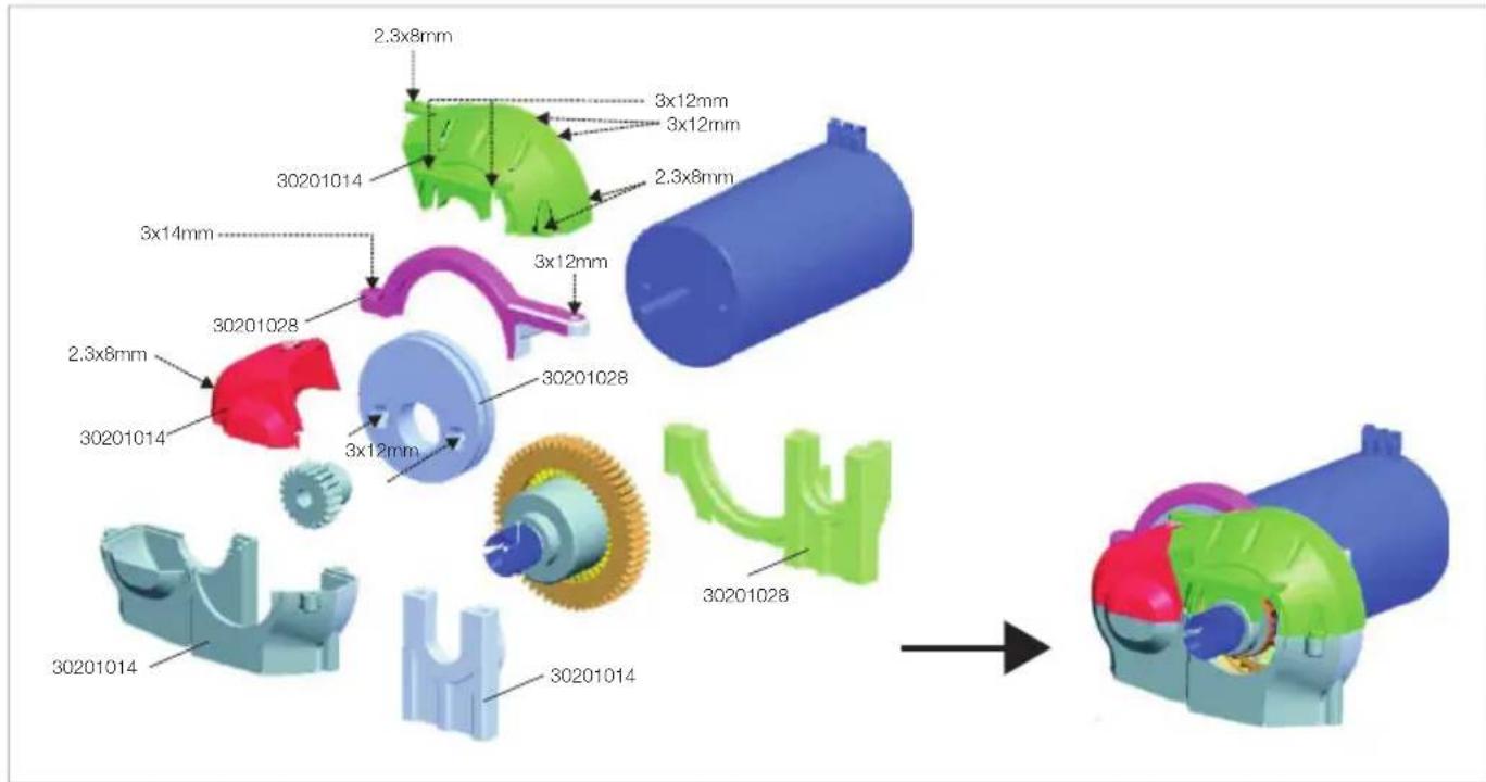
text_image
2.3x8mm 3x12mm 3x12mm 2.3x8mm 3x14mm 3x12mm 30201014 30201028 30201028 30201014 2.3x8mm 3x12mm 30201014 30201014 30201014 30201028 30201014 30201014CE
EN The XciteRC Modellbau GmbH & Co. KG declare that this product complies with the essential requirements and other relevant regulations of the directives R&TTE 1999/5/EC and RoHS 2011/65/EC.
The detailed Declaration of Conformity can be found at www.XciteRC.com at the respective product link Declaration of Conformity or via E-mail: info@xciterc.de.
text_image
Exploded view diagram of a mechanical assembly with labeled parts and dimensions in millimeters