
Quicky Classic 160 XL - Electric scooter Quickie - Free user manual and instructions
Find the device manual for free Quicky Classic 160 XL Quickie in PDF.

| Product type | Manual folding wheelchair |
| Brand | Quickie |
| Model | Quicky Classic 160 XL |
| Total weight (comfort version) | 28.4 kg |
| Maximum load capacity | 125 kg (160 kg with reinforced frame) |
| Total width (with standard wheels) | Seat width + 19.5 cm |
| Adjustable seat height | Yes (from 42 to 52 cm depending on configuration) |
| Adjustable backrest angle | 5 positions: 3° forward, 0°, 5°, 10°, 15° backward |
| Armrests | Folding, removable and height-adjustable |
| Footrests | Folding, length-adjustable (minimum ground clearance 2.5 cm) |
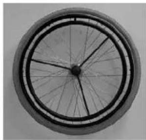
| Rear wheels | 24 inches, quick-release axles |
| Front wheels | 6, 7 or 8 inches depending on adjustment |
| Brakes | Wheel-lock brakes (optional drum brake) |
| Safety | Anti-tip casters, safety belt, reflectors |
| Maintenance | Clean with soapy water; lubricate axles every 8 weeks; check every 6 months at dealer |
| Spare parts | Tires, inner tubes, axles, cushions, footrests |
| Repairability | By Sunrise Medical authorized dealer |
| Warranty | 5 years |
| Standards | CE compliance, ISO 9001 certification |
Frequently Asked Questions - Quicky Classic 160 XL Quickie
User questions about Quicky Classic 160 XL Quickie
0 question about this device. Answer the ones you know or ask your own.
Ask a new question about this device
Download the instructions for your Electric scooter in PDF format for free! Find your manual Quicky Classic 160 XL - Quickie and take your electronic device back in hand. On this page are published all the documents necessary for the use of your device. Quicky Classic 160 XL by Quickie.
USER MANUAL Quicky Classic 160 XL Quickie
We are very happy that you have decided in favour of a high-quality product from SUNRISE MEDICAL.
This user's manual will provide numerous tips and ideas so that your new wheelchair can become a trustworthy and reliable partner in your life.
Maintaining close links with our customers is of great importance to us at Sunrise Medical. We would therefore like to keep you up-to-date with our new and current developments. Keeping close to our customers also means fast service when you need replacement parts or accessories, or just have a question about your wheelchair — and with as little red tape as possible. We want you to be satisfied with our products and service. Sunrise Medical therefore constantly works at continuous development of its products. For this reason, changes can occur in our range of products with regard to shape, technology, and fittings. Consequently, no claims can be construed from the data or pictures contained in this user's manual.
SUNRISE MEDICAL has been awarded the ISO 9001 Certificate, which affirms the quality of our products at every stage, from R & D to production.
Please contact your local, authorised SUNRISE MEDICAL dealer if you have any questions concerning the use, maintenance, or safety of your wheelchair.
In the case that there is no authorised dealer in your area or you have any questions, you can contact Sunrise Medical either in writing or by telephone (contacts are mentioned on the last page).
Sunrise Medical Ltd.
Sunrise Business Park
High Street, Wollaston West Midlands DY8 4P
England
Telephone: +44/1384-446688
Fax: +44/1384-446699
www.sunrisemedical.co.uk
Table of contentsForeword
Foreword for Wheelchairs
Transportation
Wheelchair Components 5
Handling
Folding Up and Unfolding 6
Options
Step Tubes 6
Brakes 6-7
Footplates 7
Castors
Castor Plates 8
Amputee Axle Plate 8
Backrests 8-9
Armrest 9
Push Handles 10
Lap belt instructions 10
Anti-Tip Tubes 10
Seat 11
Seat Depth 11
- Crutch Holder 11
Tray 17
Stabilizing Bar 17
- Head Rest 11
Travel Wheels 12
One Arm Drive 12
Tyres and Mounting 12
Trouble Shooting 12
Maintenance and Care 12
Technical Data 13
Nameplates/Guarantee 14
Torque 14
This manual gives information on all features sold across different countries, without stating whether they are actually available in your country or are optional or standard features. For this information please refer to the orderform/prescription form or your prescriber/supplier.
Transportation
A wheelchair secured in a vehicle will not provide the equivalent level of safety and security of a vehicle seating system. It is always recommended that the user transfers to the vehicle seating. It is recognised that this is not always practical for the user to be transferred and in these circumstances where the user must be transported whilst in the wheelchair the following advice should be followed.
- Confirm that the vehicle is suitably equipped to transport a passenger in a wheelchair, and ensure the method of access/egress is suitable for your wheelchair type. The vehicle should have the floor strength to take the combined weight of the user, the wheelchair and accessories.
- Sufficient space should be available around the wheelchair to enable clear access to attach, tighten and release the wheelchair and occupant tie down restraints and safety belts.
- The occupied wheelchair must be located in a forward facing position and secured by the wheelchair tie down and occupant restraint straps (WTORS tie downs) meeting the requirements of ISO 10542 or SAE J2249, in accordance with the WTORS manufacturers' instructions.
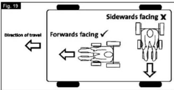
- The wheelchair's use in other positions within a vehicle has not been tested e.g. transportation in a side facing position must not be carried out under any circumstances. (Fig19)
Warning There is a risk of serious injury or death if this if this advice is ignored.
- The wheelchair should be secured by a Tie Down Restraint system, conforming to ISO 10542 or SAE J2249 with non-adjustable front straps and adjustable rear straps, which typically use Karabiner clips/S hooks and tongue and buckle fittings. These restraints generally comprise of 4 individual straps that are attached to each corner of the wheelchair.
- The tie-down restraints should be fitted to the main frame of the wheelchair as indicated in the diagram on the following page, and not to any attachments or accessories, e.g. not around the spokes of wheels, brakes or footrests.
- The tie-down restraints should be attached as close as possible at an angle of 45 degrees and tightened securely in accordance with the manufacturer's instructions.
- Alterations or substitutions must not be made to the wheelchair securement points or to structural and frame or components without consulting the manufacturer. Failure to do so will invalidate the ability of a Sunrise Medical wheelchair to be transported within a vehicle.
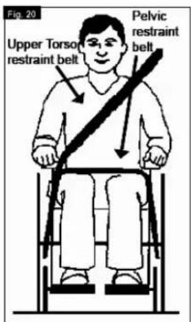
- Both pelvic and upper torso restraint belts must be used to restrain the occupant to reduce the possibility of head and chest impacts with the vehicle components and serious risk of injury to the user and other vehicle occupants. (Fig 20) The upper torso restraint belt should be mounted to the vehicle "B" pillar - failure to do so will increase the risk of serious abdominal injuries to the user.
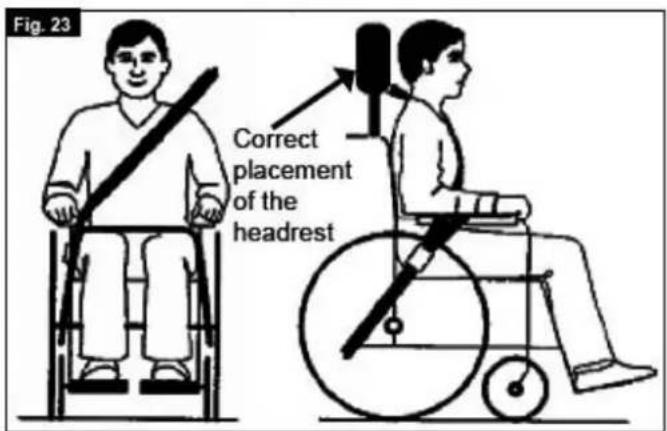
- A head restraint suitable for transportation (see label on headrest) must be fitted and suitably positioned at all times during transportation.
- Postural supports (lap straps, lap belts) should not be used or relied on for occupant restraint in a moving vehicle unless they are labelled as meeting the requirements specified in ISO 7176-19:2001 or SAE J2249.
- The safety of the user during transportation depends upon the diligence of the person securing the tie-down restraints and they should have received appropriate instructions and/or training in their use.
- Wherever possible remove and stow safely away from the wheelchair all auxiliary equipment, for example: Crutches
Loose cushions
Tray Tables
- Articulating/elevating leg rest should not be used in the elevated position when the wheelchair and user are being transported and the wheelchair is restrained using Wheelchair Transport and Occupant Restraints.
- Reclining backrests should be returned to an upright position.
- The manual brakes must be firmly applied.
Occupant Retraints Instruction
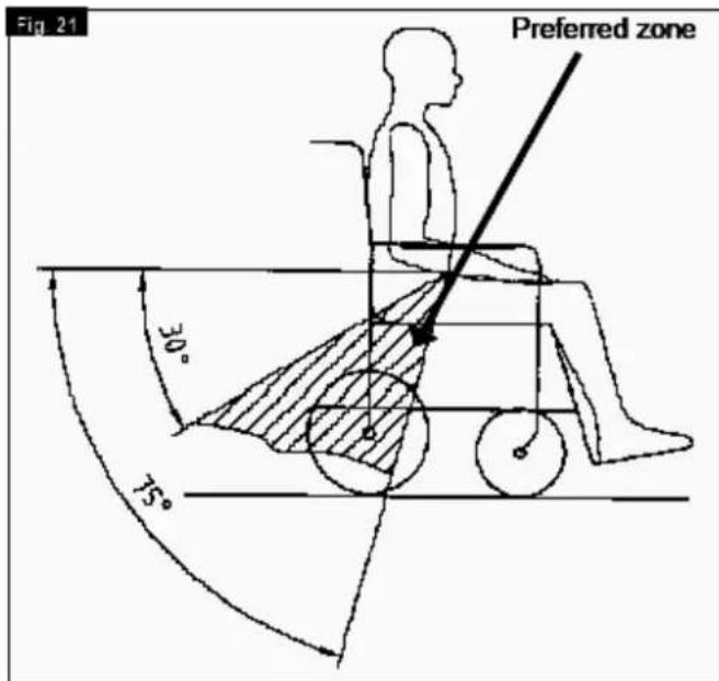
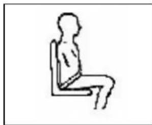
- The pelvic restraint belt must be worn low across the front of the pelvis so that the angle of the pelvic belt is within the preferred zone of 30 to 75 degrees to the horizontal.
A steeper (greater) angle within the preferred zone is desirable i.e. closer to, but never exceeding 75degrees. (Fig 21)
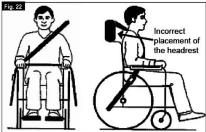
- The upper torso restraint belt must fit over the shoulder and across the chest as illustrated Fig 22 and Fig 23. Restraint belts must be adjusted as tightly as possible consistent with user comfort.
Restraint belt webbing must not be twisted when in use.
The upper torso restraint belt must fit over the shoulder and across the shoulder as illustrated in Fig 22 and Fig 23.
Restraints should be mounted to the vehicle "B" pillar and should not be held away from the body by wheelchair components such as armrest or wheels.
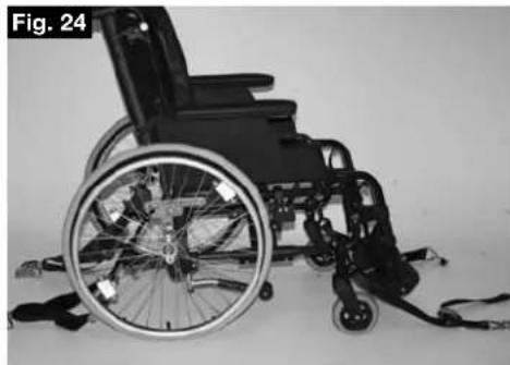
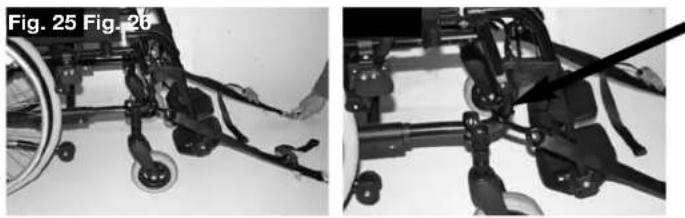
- The attachment points to the chair are the inner front side frame just above the castor and the rear side frame. The straps are fitted around the side frames at the intersection of the horizontal and vertical frame tubes. (See Figs 24-28)
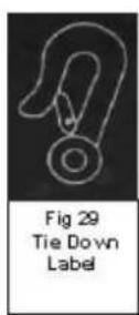
- The tie down symbol (Fig 29) on the wheelchair frame indicates the position of the wheelchair restraint straps. The straps are then tensioned after the front straps have been fitted to secure the wheelchair.
Transportability - positioning of wheelchair tie down restraints on wheelchair
The wheelchair secured with front and rear wheelchair tie down restraints. Positioning of the restraint straps is shown in more detail below.
Position of the front wheelchair tie down restraint and the tie down position.
Position of the rear wheelchair tie down restraint and the tie down position on the wheelchair.
Overview
We at SUNRISE MEDICAL have been awarded the ISO-9001 certificate, which affirms the quality of our products at every stage, from R & D to production. This products meet the requirements in accordance with EC guidelines. Options or accessories shown are available at extra cost.
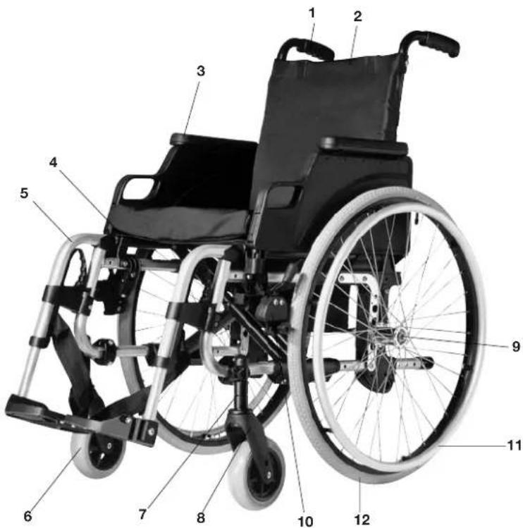
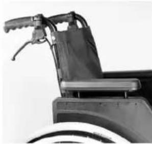
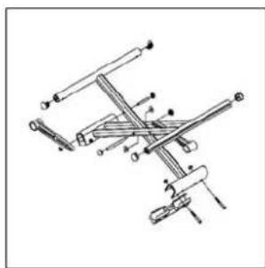
Wheelchair:
- Push handles 7. Castor adapter
- Backrest 8. Castor fork
- Sideguard 9. Quick-release axle
- Seat sling 10. Brakes
- Footrests 11. Handrim
- Castor 12. Rear wheel
Handling Options - Brakes
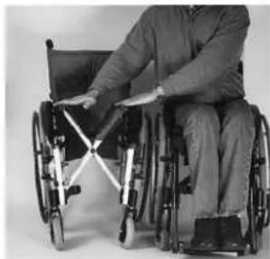
Folding up
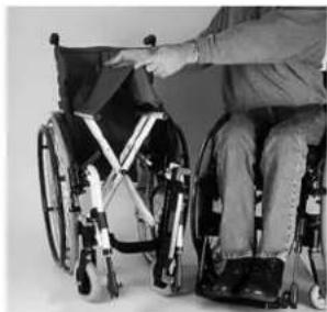
First remove the seat cushion and back shell (comfort version only) from the wheelchair and flip up the (platform) footplate or the individual footplates. Take hold of the sling from underneath in the middle and pull upwards. The wheelchair will then fold up. To fold your wheelchair until it is as small as possible, e.g., to put into a car, you can remove the footrests (depending on the model). For this purpose, open the latch from the outside and swing the footrest to the side. Then the footrest only has to be drawn out of the frame tubing.
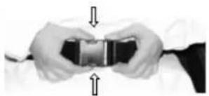
Unfolding
Press down on the seat tubing (see picture). Your wheelchair is then unfolded. Now snap the seat tubing into position in the seat saddle. This can be facilitated by slightly tipping your wheelchair. In this way, the weight can be taken
off of one rear wheel so that the wheelchair can be more easily unfolded. Be careful not to get your fingers caught in the cross-tube assembly. Finally put seat cushion and backshell on again.
Note: Make sure that the back shell snaps in correctly.
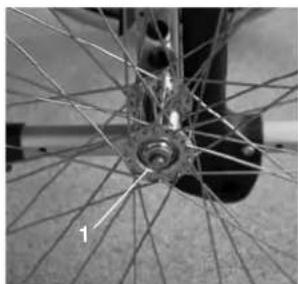
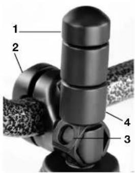
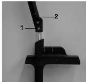
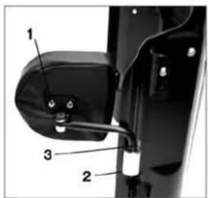
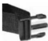
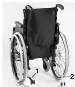
Quick-Release Axles for Rear Wheels
The rear wheels are equipped with quick-release axles. The wheels can thus be installed or removed without using tools. To remove a wheel, simply depress the quick-release button on the axle (1) and pull it out.
CAUTION:
Hold the quick-release button on the axle depressed when inserting the axle into the frame to mount the rear wheels. Release the button to lock the wheel in place. The quick-release button should snap back to its original position.
Options - Step Tubes
Step Tubes
Step tubes are used by attendants to tip a wheelchair over an obstacle. Simply step on the tube to push a wheelchair, for example, over a curb or step.
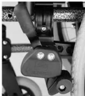
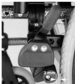
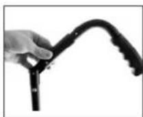
Wheel Locks
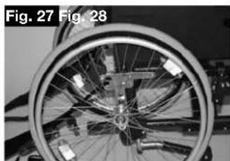
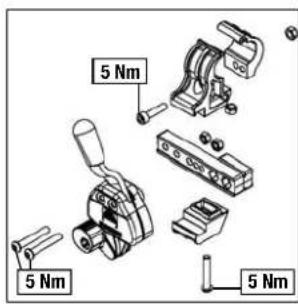
Your wheelchair is equipped with two wheel locks. They are applied directly against the tyres. To engage, press both wheel-lock levers forward against the stops (Fig. 282 and 283). To release the wheel, pull the levers back to their original positions.
Braking power will decrease with: Worn tyre tread
Tyre pressure that is too low
Wet tyres
- Improperly adjusted wheel locks.
The wheel locks have not been designed to be used as brakes for a moving wheelchair. The wheel locks should therefore never be used to brake a moving wheelchair. Always use the handrims for braking. Make sure that the interval between the tyres and wheel locks complies with given specifications (Fig. 282 and 283). To readjust, loosen screw (1) and set the appropriate interval. Tighten screw (see the page on torque)
CAUTION:
After each adjustment of the rear wheels, check the interval to the wheel locks and readjust if necessary.
Extension for the wheel lock Lever
The extension for the wheel lock lever can be removed or folded down. The longer lever helps to minimize the effort needed to set the wheel locks.
Caution:
Mounting the wheel lock too close toward the wheel will result in a higher effort to operate. This might cause the wheel lock extension lever to break!
Leaning onto the wheel lock extension lever while transferring will cause the lever to break! Splashing water from tyres might cause the wheel lock to malfunction.
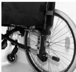
Drum Brakes
Drum brakes permit safe and convenient braking for an attendant. They can also be set with the aid of a locking lever (1) to prevent rolling. This lever must snap audibly into place. Drum brakes are not dependent on the aid of air pressure inside the tyres. Your wheelchair cannot be moved when the drum brakes are set.
CAUTION:
Drum brakes should only be adjusted by authorized dealers.
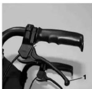
One Hand Wheel Locks
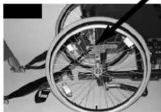
Your wheelchair is equipped with two sets of wheel locks, that operate from the left or the right side. They are applied directly against the tyres. To engage, press the wheel-lock lever forward against the stop (fig. 1). To release the wheel, pull the lever back to the original position.
Holding power will decrease with:
Worn tyre tread
Tyre pressure that is too low
Wet tyres
- Improperly adjusted wheel locks.
The wheel locks have not been designed to be used as brakes for a moving wheelchair. The wheel locks should therefore never be used to brake a moving
wheelchair. Always use the handrims for braking. Make sure that the interval between the tyres and wheel locks complies with given specifications. To readjust, loosen screw and set the appropriate interval. Tighten screw (see the page on torque).
CAUTION:
After each adjustment of the rear wheels, check the interval to the wheel locks and readjust if necessary.
Mounting the wheel lock too close toward the wheel, will result in a higher effort to operate. This might cause the brake lever extension to break! Leaning on to the brake lever extension while transferring will cause the lever to break! Splashing water from tyres might cause the wheel lock to malfunction.
Options - Footplates
Footplates
The footplates can be flipped up to facilitate getting in and getting out of your wheelchair.
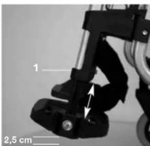
Lower Leg Length
By removing the screws (1), the legrest can be adjusted to fit any lower leg length. Loosen the screws, set the tubing with legrest in the desired position, and then tighten the screws. (See the page on torque).
A minimum interval of 2.5 centimetres from the ground should always be maintained.
Legrests and Latch
The legrest can be swung in, underneath the seat sling, or outwards.
Fit your legrest by inserting it with the footplate(s) pointing toward the in/outside. Then rotate it toward the inside until it locks into place. To remove the legrest, pull the lever (1), swing the footrest towards the in or outside and lift to remove it. Make sure that the legrest is properly locked into place.
CAUTION:
The legrests should not be used to lift or to carry the wheelchair.
Flip-up footrest (standard or with length adjustment):
To elevate:
Pull the footrest upwards and adjust it to the desired height. You will hear the footrest click into place.
To lower:
Lift the lower leg and press the release lever to unlock the footrest. You may now lower the footrest. As soon as you let go of the lever, the footrest will lock into place.
CAUTION:
Keep hands clear of the adjustment mechanism between the frame and the movable parts of the footrest while elevating or lowering the footrest.
CAUTION:
Footrests are not to be used for lifting or carrying the wheelchair.
Stump pad
The stump pad can be adjusted in all directions to fit the users need.
Options - Castor
Castors, Castor Plates, Forks
From time to time the wheelchair may veer slightly to the right or left, or the castors may flutter. This may be caused by the following:
- Forward and/or reverse wheel motion has not been set properly.
The castor angle has not been adjusted properly. - Castor and/or rear wheel air pressure is incorrect; wheels do not turn smoothly.
The wheelchair will not move in a straight line if the castors have not been properly adjusted. Castors should always be adjusted by an authorized dealer. The castor plates must be readjusted, and the wheel locks must be checked any time the rear wheel position has been altered.
Options - Castor Plates
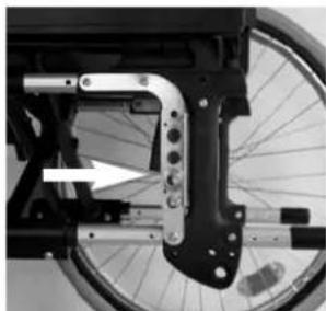
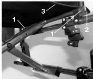
Seat height and seat angle adjustment
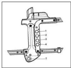
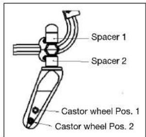
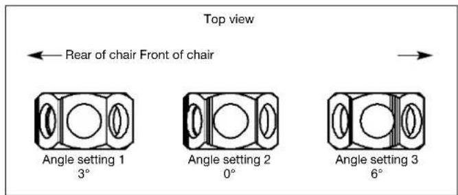
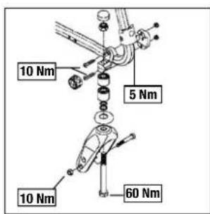
Remove the nut (1) and the axle from the castor adapter (2). To adjust the seat height to configure the spacers (4) according the seat height matrix. Finally position the collar (3) to the desired chair tilt, taking NOTE of the notches located on the top side (Fig. 2).
Angle setting 1 = 3^ (rear of chair) Angle setting 2 = 0^ Angle setting 3 = 6^ (front of chair)
Adjust the collar in such a way that the axle is as close to perpendicular to the ground as possible. When finished, make sure that all scrwes have been correctly tightened (see the page on torque).
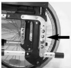
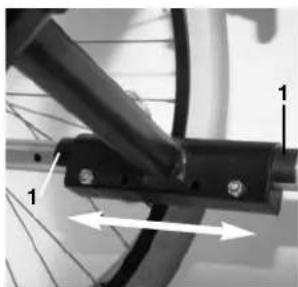
Horizontal Axle Position
The axle plate can be positioned forward for maximum maneuverability or rearward for increased stability.
CAUTION: Wheel locks must be adjusted to suit the new position.
The longer the wheel base, the greater the stability of the wheelchair. Turn the axle bracket to the rear (1) in order to extend the wheel base.
CAUTION: Wheel locks must be adjusted to suit the new position.
Options - Amputee Axle Plate
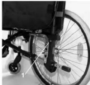
Amputee Axle Bracket
With the amputee support (accessory) the wheel base can be extended by 10,5cm . When you have completed the adjustment, make sure that all screws have been properly tightened (see the page on torque).
CAUTION:
Wheel locks must be adjusted to suit the new position.
Options-Backrest
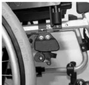
Height adjustable backrest
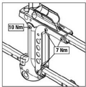
The backrest height can be adjusted to 5 different positions (38-40 cm). Open and remove the bolt (1) and move the back tube into the desired position. Then fix the bolt again.
Angle-Adjustable backrests
The backrest can be adjusted to 5 different positions (3° forward, 0°, 5°, 10° and 15° backwards). A nut (1) is located on the backtube, allowing you to set the angle. Angle adjustment of the back post will require adjustment of the armrest „hook“ support.
CAUTION:
The screws (1) connect the
backrest directly to the frame;
always ensure they are tightened correctly.
Screws that are too loose can be easily lost. In
either case, injuries could result when using the push handles to ascend stairs.
For your own safety, we recommend that adjustments only be made by authorized dealers.
The back rest height as well as the height of the pivot point can be adjusted.
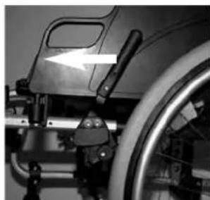
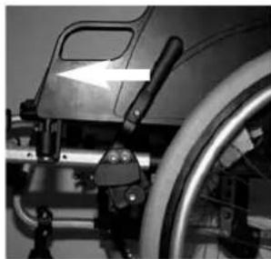
Half folding backrest
For folding the back down slight up the lock.
CAUTION:
Make sure that the backrest locks in correctly when it is set upright again.
Reclining back (8^ - 40^ / 50^)
By pulling the 2 levers (1) at the same time the backrest is released and can be set to the desired position.
Releasing the 2 levers (1) will lock the backrest automatically in the new position. To bring the backrest back in the upright position, just move it (no release necessary) to the required position.
CAUTION:
The reclining back is only allowed to be used in combination with rear wheel extension.
CAUTION:
The reclining back is recommended to be used in combination with active anti-tips (max ground clearance 3-5 cm)
CAUTION:
The reclining back is recommended to be used in combination with a stabilizer bar.
CAUTION:
In order to avoid any reduction in the cable function, you must make sure that the cables are not completely taut.
CAUTION:
When adjusting the back angle, be careful not to get your fingers caught.
CAUTION:
Never adjust the back angle if you are on a slope.
Adjustable Backrest Upholstery
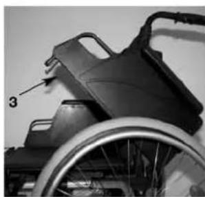
The sling can be adapted to any degree of tension by adjusting the Velcro fasteners. The padding in the backrest can be removed through an interior opening, allowing you to cushion the backrest according to your individual needs.

Comfort back
The comfort back permits comfortable long seating with lateral support. The complete can be removed by lifting up and pushing forward. The cushion is fixed by velcro and can be removed as well. The cover is washable (see label).
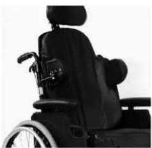
Trunk support
The trunk support can be adjusted in angle, depth and height. It can be swing away by lifting it upwards.
- Depth adjustment: Remove the 2 screws(1) and fit the trunk support in the new position. Finally tighten screws again.
Angle adjustment: Open screw (2), set the trunk support into the wished Angle and tighten the screw (2) again. - Height adjustment: Remove the fixing screws of the bracket (3) and move the bracket into the wished position. Finally tighten the screws again.
Options - Armrest
Standard armrest, Flip-Up, Detachable with desk or full Armrests
The front of the armrest is shaped to allow you to pull up close to a desk or table top. To flip the guard up, push the tab to unlock the armrest. The height of the armrest can be adjusted by installing the spacers in one of several positions. To do so, you must first loosen the screws, re configure the spacers and then retighten the
screws (see the page on torque). The inner pad is fixed with Velcro and can be removed to increase seat width.
CAUTION:
Neither the armrest nor the armpads are to be used for lifting or carrying the wheelchair.
Standard armrest, Flip-Up, Detachable with desk or full Armrests
Adjust the height of the armrest as follows: Press the tab (1) upward and move to the desired position. Release the tab and push the armpad (2) down until you can hear it locks into place. Always make sure that the armrest have locked into place properly.
To flip the armrest up, press the lever (3) to unlock the sideguard.
CAUTION:
Neither the armrest nor the armpads are to be used for lifting or carrying the wheelchair.
CAUTION:
24^a rear wheels require the armpad to be re-adjusted by one setting (upwards), to avoid finger entrapment!
Options - Push Handles
Height-Adjustable Push Handles
These handles are secured with pins to prevent them from sliding out unintentionally. Opening the quick-release lever (1) makes it possible to adjust the push handles to meet your individual needs. As you move the lever, you will hear a locking mechanism; you may now easily position the push handle as desired. The nut (2) on the tension lever determines how
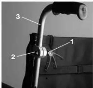
tightly the push handles are clamped into place. If the nut is loose after adjusting the tension lever, the push handle will also be too loose. Turn the push handle from side to side before use to make sure that it is clamped securely enough into place. After adjusting handle height, always clamp the tension lever (1) securely into place. If the lever is not secure, injuries could result when ascending stairs.
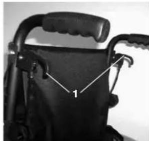
Options-Lap belt instructions
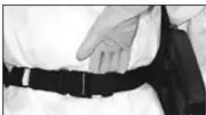
Before using your wheelchair ensure the seat belt is worn and correctly adjusted before use.
The lap belt is fitted to the wheelchair as shown in the illustrations. The lap belt is fitted between the armrest support and the backrest tube. The belt should then be run across the outside of the back upholstery.
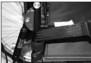
It is important that the belt is routed around the back of the wheelchair. The buckle end can be fed between the armrest and backrest.
Adjust the belt position so that the buckles are in the centre of the seat.
Adjust the lap belt to suit the user's needs as follows:
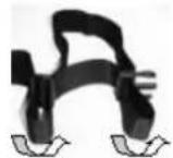
Feed the belt through slide adjust-sters and male buckle to provide more belt length.
Feed the belt back through male buckle and slide adjusters.
Ensure the belt is not looped at the male buckle
When fastened check space between the lap belt and the user, when correctly adjusted it should be possible to insert the flat of the hand between the lap belt and the user.
Generally the Lap Belt should be fixed so that the straps sit at an angle of approximately 45^ , and when correctly adjusted should not allow user to slip down in the seat.
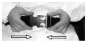
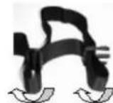
To fasten buckle: -
Firmly push the male buckle into female buckle.
To release belt: -
Press the exposed sides of the male buckle and push towards the centre whilst gently pulling apart.
Do not rely on the lap belt only when the wheelchair and occupant are transported in a vehicle, use the separate occupant lap and diagonal restraints provided in the vehicle.
Advice to Client
The lap belt must be checked on a daily basis to ensure it is adjusted correctly and it is free from any obstruction or adverse wear.
Failure to make sure that the lap belt is secure and adjusted prior to use could cause serious injury to the user. E.g. too loose a strap may allow the user to slip down in the chair and risk suffocation.
Maintenance
Check lap belt, and securing components; at regular intervals for any sign of fraying or damage. Replace if necessary.
Clean the lap belt with warm soapy water and allow to dry.
Note
The lap belt should be adjusted to suit the end user as detailed above
Sunrise Medical also recommend that the length and fit of the belt is checked on a regular basis to reduce the risk of the end user inadvertently re-adjusting the belt to an excessive length
If in doubt about the use and operation of the seat belt then ask your healthcare professional, wheelchair dealer, carer or attendant for assistance.
Options - Anti-Tip Tubes
Anti-tip tubes
Anti-tip tubes (1/2) provide additional safety for inexperienced users when they are still learning how to operate their wheelchairs. Anti-tip tubes (1/2) prevent a wheelchair from tipping over backwards.
Swing away anti-tips:
Pushing the anti-tip tubes (1) will move them downwards; they can also be swung forward. An interval of 3cm to 5 cm should be maintained between them and the ground.
You must swing the anti-tip tubes forward when going up and down large obstacles (such as a kerb) to prevent them from touching the ground.
End tube style anti-tips:
Pressing the release button allows the anti-tip tubes (2) to be moved upwards or removed. An interval of 3cm to 5cm should be maintained between them and the ground.
You must rotate the anti-tip tubes upwards when going up and down large obstacles (such as a kerb to prevent them from touching the ground.
Rotate anti-tip tubes down into functional position after overcoming obstacle.
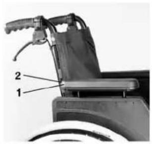
Options - Seat
Standard Sling
The sling is equipped with a Velcro fastener on one side; this permits stepless adjustment of the sling. To readjust the sling, first fold up the wheelchair slightly. Then remove the screws (1) and pull the front plugs (2) forward out of the frame. The sling (3) can then be slid off of the frame. By unfastening the
Velcro, the sling can be readjusted.
Reverse this procedure to reinstall
the sling. When finished, make sure that all screws have been properly tightened (see the page on torque).
CAUTION:
For safe use, at least 50% of the Velcro surfaces must make contact with each other at all times.
Comfort seat
The comfort seat permits comfortable long seating due to the wooden base and the anatomically shaped cushion.
Options - Seat Depth
Seat Depth
By removing the clips (1), the cross-tube assembly (2) can be moved along the frame, thereby allowing the seat depth to be changed (depending on the position of the back tubes).
Make sure that the clips (1) always snap into the holes provided in the frame.
To keep the frame as compact as possible the seat depth also can be adjusted via the back tubes
(41-46 cm in 2,5 cm increments). Therefore remove the axle plate screws (1,2,3). Remove the wheels
and the armrests and check if the cross brace is in the desired position (slide cross brace if necessary as described above). Move the back tubes into the required position and fix all 3 screws again. Finally move the receiver of the armrest into the required position.
CAUTION:
Wheel locks must be adjusted for the new position.

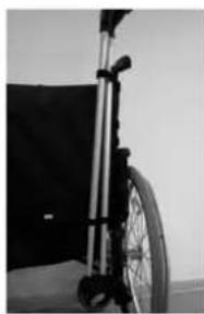
Options - Crutch Holder
Crutch Holder
This device permits crutches to be transported directly on a wheelchair. It has a Velcro loop (1) to fasten crutches or other aids.
CAUTION:
Never try to use or even remove the crutches or other aids while moving.
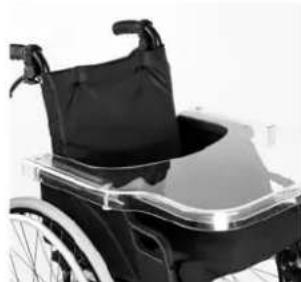
Options - Tray
Tray
The tray provides a flat surface for most activities. Before using a tray, it first has to be adjusted to the width of the seat by an authorized dealer. The user must be sitting in the wheelchair whilst this adjustment is made.
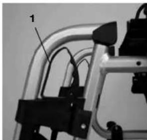
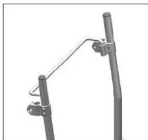
Options - Stabilizing Bar
Stabilizing Bar
This bar is used to stabilize the backrest. To be able to fold up your wheelchair, remove the stabilizing bar. Now you can easily fold up the wheelchair. To reinstall the stabilizing bar, locate it back into place.
Options - Head Rest
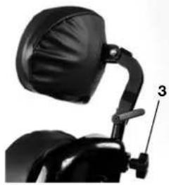
Headrest
The headrest can be raised and moved both forwards and backwards. To do this, simply loosen the screw (1 or 2), adjust to the desired position, and tighten the screw (see the page on torque).
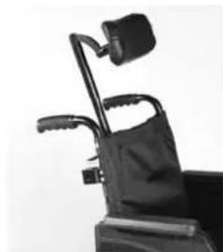
Comfort Head rest
For adjusting the height open knob (3) and position the headrest in the desired height. Finally tighten the knob again.
Options - Travel Wheels
Travel Wheels
Travel wheels should be used wherever your wheelchair would be too wide if the rear wheels were used (e.g., in airplanes, buses, etc.). After the rear wheels have been removed with the aid of the quick-release axles, the transit wheels can immediately be used to continue riding. The transit wheels are mounted so that they are approx. 3 centimeters above the ground when not in use. They are thus out of the way when riding, transporting, or when tipping to pass over obstacles (e.g., kerbs, steps, etc.).
CAUTION:
Your wheelchair does not have any wheel locks when the transit wheels are being used.
Options - One Arm Drive
One arm drive
To propel the chair straight forward both handrims must be used. To fold the wheelchair disconnect the telescopic bar by pushing it inwards.
CAUTION:
Make always sure that the connections are set properly to avoid injuries.
Tyres and Mounting
Tyres and Mounting
Always make sure you that you maintain the correct tyre pressure, as this can have an effect on wheelchair performance. If the tyre pressure is too low, rolling resistance will increase, requiring more effort to move the chair forward. Low tyre pressure also has a negative impact on maneuverability. If the tyre pressure is too high, the tyre could burst.
The correct pressure for a given tyre is printed on the surface of the tyre itself.
Tyres can be mounted the same way as an ordinary bicycle tyre. Before installing a new inner tube, you should always make sure that the base of the rim and the interior of the tyre are free of foreign objects. Check the pressure after mounting or repairing a tyre. It is critical to your safety and to the wheelchair's performance that regulation air pressure be maintained and that tyres be in good condition.
Trouble Shooting
Wheelchair pulls to one side
Check tyre pressure
- Check to make sure wheel turns easily (bearings, axle)
- Check angles of castors
- Check to make sure both castors are making correct contact with the ground
Castors begin to wobble
- Check angle of castors
- Check to make sure all bolts are secure; tighten if necessary (See the page on torque)
- Check to make sure both castors are making proper contact with the ground
Wheelchair / Cross-tube assembly does not snap into position in the seat saddle
Chair is still new, i.e., the seat or backrest upholstery is still very stiff. This will improve with continued use.
Wheelchair is difficult to fold up
- Adjustable backrest upholstery is too stiff; loosen it accordingly.
Wheelchair squeaks and rattles
- Check to make sure bolts are secure; tighten if necessary (see the page on torque)
- Apply small amount of lubrication to spots where movable parts come in contact with one another
Wheelchair begins to wobble
- Check angle at which castors are set
- Check tyre pressure
- Check to see if rear wheels are adjusted differently
Maintenance and Care
Maintenance
- Check the tyre pressure every 4 weeks. Check all of the tyres for wear or damage.
- Check the brakes approximately every 4 weeks to make sure that they are working properly and easy to use.
- Change tyres as you would an ordinary bicycle tyre.
- All of the joints that are critical to using your wheelchair safely are self-locking nuts. Check every three months to make sure that all bolts are secure (See the page on torque). Self locking nuts should only be used once and should be replaced after single use.
- Use only mild household cleansers when your wheelchair is dirty. Use only soap and water when cleaning the seat upholstery.
- If your wheelchair should ever get wet, please dry it after use.
- A small amount of sewing-machine oil should be applied to quick-release axles approximately every 8 weeks. Depending on the frequency and type of use, we recommend taking your wheelchair to your authorized dealer every 6 months to have it inspected by trained personnel.
CAUTION:
Sand and sea water (or salt in the winter) can damage the bearings of the front and rear wheels. Clean the wheelchair thoroughly after exposure to these conditions.
Technical Data
Total width:
- With standard wheels, incl. Hand rims, close-mounted:
Classic 100: SW +19,5 cm
Classic 160: SW +19.5 cm
- Wheels with drum brakes, hand rims, close-mounted;
Classic 100: SW +21 cm
Classic 160: SW +21 cm
Dimensions, folded:
With rear wheels: Classic 100:37 cm Classic 160:33 cm
Without rear wheels: Classic 100:26 cm Classic 160:23 cm
Weight in kilograms:
Wheelchair without footrests (24") 13,9 kg
Footrests 1,6 kg
Standard sideguards 2 kg
Rear wheels 24" (solid) 4.2 kg
Rear wheels, MAG 5 kg
Maximum weight limit:
Approved for user weights up to 125 kg / 265 lbs
Heavy duty version 160 kg/352 lbs
Weight: total comfort chair
(including ELR, reclining back) 28,4 kg
- Comfort seat (including wooden base) 2,6 kg
- Comfort back cushion 1,1 kg
- Comfort back shell including cushion 3,3 kg
Head rest 0,6 kg
ELR(pair) - Comfort armrest (pair) 2,8 kg
Possible seat-height adjustments
Seat height matrix showing possible seat height adjustments including castor/wheel options and mounting positions.
CAUTION: Measured without seat cushion.
| front seat angle rear rear castor castor no ofseat angle setting wheel/ wheel wheel wheel spacers | ||||||
| height | tyre | pos. | pos. | below | ||
| Classic 100 | ||||||
| 42 | 3° | 1 | 22" | 1 | 6" / 140 mm | 1 |
| 44 | 3° | 1 | 24" | 1 | 6" / 140 mm | 2 |
| 47 | 3° | 1 | 24" | 2 | 6" / 140 mm | 1 |
| 50 | 3° | 1 | 24" | 3 | 6" / 140 mm | 2 |
| 47 | 3° | 1 | 24" | 2 | 8" / 200 mm | 2 |
| 50 | 3° | 1 | 24" | 3 | 8" / 200 mm | 2 |
| 52 | 6° | 3 | 24" | 3 | 8" / 200 mm | 2 |
| 47 | 3° | 1 | 24" | 2 | 7" / 200 mm | 2 |
| 50 | 3° | 1 | 24" | 3 | 7" / 180 mm | 2 |
| 52 | 3° | 1 | 24" | 4 | 7" / 180 mm | 2 |
| 45 | 3° | 3 | 12" | T | 6" / 180 mm | 2 |
| 47 | 6° | 3 | 12" | T | 8" / 120 mm | 2 |
| 42 | 3° | 2 | 16" | T | 6" / 140 mm | 1 |
| 50 | 3° | 2 | 16" | T | 6" / 140 mm | 2 |
| 50 | 3° | 2 | 16" | T | 8" / 200 mm | 2 |
| Classic 160 | |||||||
| 42 | 3° | 1 | 22" | 1 | 6" / 140 mm | 1 | 0 |
| 42 | 0° | 2 | 22" | 2 | 6" / 140 mm | 1 | 0 |
| 42 | 0° | 2 | 24" | 1 | 6" / 140 mm | 1 | 0 |
| 44 | 3° | 1 | 24" | 1 | 6" / 140 mm | 2 | 0 |
| 44 | 0° | 2 | 24" | 2 | 6" / 140 mm | 2 | 0 |
| 47 | 6° | 3 | 24" | 1 | 6" / 140 mm | 1 | 2 |
| 47 | 3° | 1 | 24" | 2 | 6" / 140 mm | 1 | 2 |
| 47 | 0° | 2 | 24" | 3 | 6" / 140 mm | 1 | 2 |
| 50 | 6° | 3 | 24" | 2 | 6" / 140 mm | 2 | 2 |
| 50 | 3° | 1 | 24" | 3 | 6" / 140 mm | 2 | 2 |
| 50 | 0° | 2 | 24" | 4 | 6" / 140 mm | 2 | 2 |
| 47 | 6° | 3 | 24" | 1 | 8" / 200 mm | 2 | 0 |
| 47 | 3° | 1 | 24" | 2 | 8" / 200 mm | 2 | 0 |
| 47 | 0° | 2 | 24" | 3 | 8" / 200 mm | 2 | 0 |
| 50 | 6° | 3 | 24" | 2 | 8" / 200 mm | 2 | 1 |
| 50 | 3° | 1 | 24" | 3 | 8" / 200 mm | 2 | 1 |
| 50 | 0° | 2 | 24" | 4 | 8" / 200 mm | 2 | 1 |
| 52 | 6° | 3 | 24" | 3 | 8" / 200 mm | 2 | 2 |
| 52 | 3° | 1 | 24" | 4 | 8" / 200 mm | 2 | 2 |
| 47 | 6° | 3 | 24" | 1 | 7" / 180 mm | 2 | 0 |
| 47 | 3° | 1 | 24" | 2 | 7" / 180 mm | 2 | 0 |
| 47 | 0° | 2 | 24" | 3 | 7" / 180 mm | 2 | 0 |
| 50 | 6° | 3 | 24" | 2 | 7" / 180 mm | 2 | 1 |
| 50 | 3° | 1 | 24" | 3 | 7" / 180 mm | 2 | 1 |
| 50 | 0° | 2 | 24" | 4 | 7" / 180 mm | 2 | 1 |
| 52 | 6° | 3 | 24" | 3 | 7" / 180 mm | 2 | 2 |
| 52 | 3° | 1 | 24" | 4 | 7" / 180 mm | 2 | 2 |
| 42 | 0° | 2 | 12" | T | 6" / 140 mm | 1 | 0 |
| 45 | 3° | 1 | 12" | T | 6" / 140 mm | 1 | 1 |
| 47 | 6° | 3 | 12" | T | 6" / 140 mm | 1 | 2 |
| 47 | 6° | 3 | 12" | T | 8" / 200 mm | 2 | 0 |
| 42 | 3° | 1 | 16" | 4 | 6" / 140 mm | 1 | 0 |
| 47 | 0° | 2 | 16" | T | 6" / 140 mm | 1 | 2 |
| 50 | 3° | 1 | 16" | T | 6" / 140 mm | 2 | 2 |
| 47 | 0° | 2 | 16" | T | 8" / 200 mm | 2 | 0 |
| 50 | 3° | 1 | 16" | T | 8" / 200 mm | 2 | 1 |
Nameplates/Guarantee
Nameplates
The nameplate is located on either the cross-tube assembly or the transverse frame tube, as well as on the back page of the user's manual. The nameplate indicates the exact model designation and other technical specifications. Please provide the following information whenever you have to order replacement parts or to file a claim:
-
Serial number
-
Order number
Month/Year
Guarantee
You have purchased a high-quality SUNRISE MEDICAL product. As a sign of our gratitude, we are providing you with 5-year guarantee on all frame components and the cross-tube assembly. We are not responsible for any damage resulting from inappropriate or unprofessional installation and/or repairs, through neglect and wear, or from changes in any wheelchair components caused either by the user or by third parties. In such cases, this guarantee shall be considered null and void.
Custom wheelchairs cannot be exchanged.
Torque

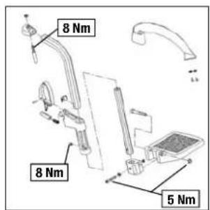
Torque The torque for the M6 screw is 7 Nm, unless otherwise specified.
Chere cliente, Cher client,
Manipulation Options - Freins
Plier
Options - Repose-pied
Repose-pied
Toile arrriere comfort
Roulettes anti-bascule
Roulettes anti-bascule escamotables:
$$ \text {D a t i} \tag {36} $$
$$ \text {T a r g h e t t a d i d e n i s t i f i c a z i o n e / G a r a n z i a} \dots 3 7 $$
$$ \text {T o r q u e c o p p i e d i s e r r a g g i o} \dots . 3 7 $$
Classic 100: SW +19.5 cm
Classic 160: SW +19,5 cm
Sunrise Medical B.V.
Groningenhaven 18-20
3433 PE NIEUWEGEIN
Nederland
Telefoon: +31(0)30 6082100
Fax: +31(0)30 6055880
E-mail: info@sunrisemedical.nl
Voorwoord
Veiligheidstips
Inklappen (Zie figure 1)


- Sunrise Medical Ltd.
- Table of contentsForeword
- Transportation
- Occupant Retraints Instruction
- Overview
- Wheelchair:
- Handling Options - Brakes
- Folding up
- Unfolding
- Quick-Release Axles for Rear Wheels
- CAUTION:
- Options - Step Tubes
- Step Tubes
- Wheel Locks
- Extension for the wheel lock Lever
- Drum Brakes
- One Hand Wheel Locks
- Options - Footplates
- Footplates
- Lower Leg Length
- Legrests and Latch
- Flip-up footrest (standard or with length adjustment):
- To elevate:
- To lower:
- Stump pad
- Options - Castor
- Castors, Castor Plates, Forks
- Options - Castor Plates
- Seat height and seat angle adjustment
- Horizontal Axle Position
- Options - Amputee Axle Plate
- Amputee Axle Bracket
- Options-Backrest
- Height adjustable backrest
- Angle-Adjustable backrests
- Half folding backrest
- Reclining back (8° - 40° / 50°)
- Adjustable Backrest Upholstery
- Comfort back
- Trunk support
- Options - Armrest
- Standard armrest, Flip-Up, Detachable with desk or full Armrests
- Options - Push Handles
- Height-Adjustable Push Handles
- Options-Lap belt instructions
- Before using your wheelchair ensure the seat belt is worn and correctly adjusted before use.
- It is important that the belt is routed around the back of the wheelchair. The buckle end can be fed between the armrest and backrest.
- Adjust the lap belt to suit the user's needs as follows:
- To fasten buckle: -
- To release belt: -
- Do not rely on the lap belt only when the wheelchair and occupant are transported in a vehicle, use the separate occupant lap and diagonal restraints provided in the vehicle.
- Advice to Client
- Maintenance
- Note
- Options - Anti-Tip Tubes
- Anti-tip tubes
- Swing away anti-tips:
- End tube style anti-tips:
- Options - Seat
- Standard Sling
- Comfort seat
- Options - Seat Depth
- Seat Depth
- Options - Crutch Holder
- Crutch Holder
- Options - Tray
- Tray
- Options - Stabilizing Bar
- Stabilizing Bar
- Options - Head Rest
- Headrest
- Comfort Head rest
- Options - Travel Wheels
- Travel Wheels
- Options - One Arm Drive
- One arm drive
- Tyres and Mounting
- Trouble Shooting
- Wheelchair pulls to one side
- Castors begin to wobble
- Wheelchair / Cross-tube assembly does not snap into position in the seat saddle
- Wheelchair is difficult to fold up
- Wheelchair squeaks and rattles
- Wheelchair begins to wobble
- Maintenance and Care
- Technical Data
- Total width:
- Dimensions, folded:
- Weight in kilograms:
- Maximum weight limit:
- Weight: total comfort chair
- Possible seat-height adjustments
- CAUTION: Measured without seat cushion.
- Nameplates/Guarantee
- Nameplates
- Guarantee
- Torque
- Manipulation Options - Freins
- Plier
- Options - Repose-pied
- Repose-pied
- Toile arrriere comfort
- Roulettes anti-bascule
- Roulettes anti-bascule escamotables:
- Sunrise Medical B.V.
- Nederland
- Voorwoord
- Veiligheidstips
- Inklappen (Zie figure 1)
Brand : Quickie
Model : Quicky Classic 160 XL
Category : Electric scooter