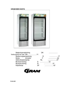
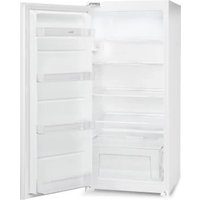
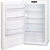
USER MANUAL MIDI KG GRAM
| Betjeningsvejledning | DK | ...... |
| Instructions for use GB ......11 | | |
| Bedienungsanweisung | D | ......17 |
| Mode d'emploi | F | ......22 |
| Gebruiksaanwijzing | NL | ......27 |
| Bruksanvisning | S | ......32 |
| Bruksanvisning | N | ......37 |
| Käyttöohje | SF | ......42 |
GRAM
Electrical connection 12
Starting up 13
Temperature setting 13
Error codes on the display 14
Defrosting 14
Defrost water 15
Door closing mechanism 15
Fluorescent tube replacement 15
Power failure 15
Cleaning 15
Service 16
Disposal 16
D Inhalt
Aufstellen 17
Important! 17
Power connection 18
Switching on 18
Temperature control 18
Fault indicators 19
Defrosting 19
Watts Heating element
Refrigerant gr
Permissible operation over-pressure: Suction side: Discharge side:
ENGLISH
Location
The cabinet should be located in a dry and adequately ventilated room. To ensure efficient operation, it must not be placed in direct sunlight or against heat-emitting surfaces. Level the cabinet by adjusting the castors up or down in the wheel bracket under the cabinet.
Cabinets with external compressor
Castors on cabinets with external compressor must be braked. The cabinets must not be pulled out, as the refrigeration pipes may be damaged.
Important!
WARNING!
Do not block vent holes in the front panel.
Do not damage the refrigeration system.
Do not use electrical devices inside the cabinet.
To ensure correct and efficient air flow in the cabinet, the shaded areas must be kept free of products.

Electrician connection
The cabinet is intended for connection to alternating current. The connection values for voltage (V) and frequency (Hz) are given on the nameplate inside the cabinet. Power must be connected via a wall socket. The wall socket should be easily accessible.
All earthing requirements stipulated by the local electricity authorities must be observed. The cabinet plug and wall socket should then give correct earthing. If in doubt, contact your local supplier or authorized electrician.
Warning!
This cabinet must be earth.
The flexible cord fitted to this appliance has three cores for use with a 3-pin 13-Amp or 3-pin 15-Amp plug. If a B.S. 1363 (13-Amp) fused plug is used, it should be fitted with a 13-Amp fuse.
Important
The wires in this mains lead are coloured in accordance with the following code: GREEN-AND-YELLOW: EARTH BLUE: NEUTRAL
BROWN: LIVE
The colours of the wires in the mains lead of this appliance might not correspond with the colour marking identifying the terminals in your plug.
Proceed as follows:
Connect the GREEN-AND-YELLOW wire to the plug terminal marked by "E" or an earth symbol, or coloured GREEN-AND-YELLOW.
Connect the BLUE wire to the plug terminal marked "N" or coloured BLACK. Connect the BROWN wire to the plug terminal marked "L" or coloured RED.
Starting up
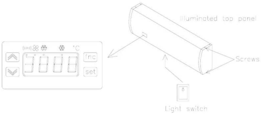
Connect the appliance to a suitable power supply.
The numbers now shown in the display indicate the actual temperature in the cabinet and also that power is on. The diode under ⚙️ indicates that the compressor is running.
A switch is located under the illuminated top panel. When the switch is pressed, all lights in the cabinet and the panel go out.
NOTE when servicing: If service work is performed on electrical parts, isolate the appliance by unplugging it from the power supply.
Temperature setting
If desired, the temperature can be changed by the controller concealed behind the light screen. (The controller is concealed to prevent the settings being tampered with). To gain access to the controller, first remove the right hand end piece on the illuminated panel by loosening the top and bottom screws (see drawing under "Starting up"). The plastic light screen can now be drawn about 10 cm to the right to give access to the controller.
Temperature check:
Press the set key lightly, "set" is displayed.
Pressing the set key lightly again will display the set temperature. If more than 15 seconds passes without any operation of the keys, the controller returns to normal operation. Pressing the key will also cause a return to normal operation.
Temperature regulation:
Press the set key lightly, "set" is displayed.
Pressing the set key lightly again will display the set temperature. The temperature can now be changed, either by pressing the key (for higher temperature) or the key (for lower temperature).
When the display shows the desired temperature, the setting has been made.
Note:
The temperature indicated by the display is always measured at the warmest point in the cabinet. The display can therefore show a temperature which is about 2° to 3° C higher than the coldest temperature in the cabinet. If, for example, the setting is 2° C, the lowest temperature in the cabinet could be 0° C. This might be important if products unable to withstand frost are being stored.
Error codes on the display
E1: If fault code E1 is displayed, the temperature sensor is defective and service assistance should be requested.
In the meantime the cabinet itself will try to maintain the set temperature.
E2: If the display shows fault code E2, the evaporator sensor is defective. This has no effect on the operation of the cabinet, but the sensor should be replaced as soon as possible. Request service assistance.
Defrosting
Defrosting is automatically performed - twice (KG) / 6 times (FG) - every 24 hours. If the cabinet is operating under severe load (frequent door opening and frequent replenishment), manual defrosting can become necessary. The cabinet can be
manually defrosted by pressing the key for approx. 5 seconds. It will then start to defrost, and the diode under will light up until defrosting is finished. The next defrosting will automatically begin 12 (KG) / 4 (FG) hours later.
Warning !!
Do not use mechanical devices or other means to accelerate the defrosting process.
Defrost water
Defrost water is led through a tube in the insulation, down to a tray under the cabinet. A heating element in the tray re-evaporates the water. It may be necessary to clean the re-evaporation tray, minimum once a year.
The tray can be removed from the rear of the cabinet, without using tools.
Door closing mechanism
The door is equipped with a self-closing system.
Fluorescent tube replacement
Note! Remember to disconnect the appliance at the socket before replacing the fluorescent tube.
In the 425 l cabinet the fluorescent tube is located inside the cabinet on the left. In the 625 l cabinet there is a fluorescent tube on both sides. The tubes are placed behind a protective screen and behind the screen on the illuminated top panel.
Access to the cabinet fluorescent tube can be gained by loosening the two screws in the protective screen. Then press lightly on both sides at the top of the screen and draw it out. The defective fluorescent tube can now be replaced and the screen refitted.
Access to the fluorescent tube behind the screen on the illuminated top panel can be gained by removing the right-hand end piece after loosening the top and bottom screws in the end piece (see drawing under "starting up"). The plastic sheet in front of the control and the fluorescent tube can now be removed. The defective tube can then be replaced and the screen and end piece refitted.
Power failure
On power failure, the control remembers the temperature setting and restarts the cabinet when current is restored. If the power failure persists for some time, the control might revert to the factory setting.
Cleaning
The cabinet should be cleaned internally with a mild soap solution at suitable intervals and checked thoroughly before it is put into operation again.
Cleansing agents containing chlorine or compounds of chlorine as well as other corrosive means, are not to be used, as they might cause corrosion to the stainless panels inside the cabinet and the evaporator system.
The compressor compartment and in particular the condenser must be kept free from dust and dirt. This is best done with a vacuum cleaner and a brush.
The air filters on the condenser and the front panel can be removed and cleaned in a dishwasher at max. 50°C.
Do not flush compressor compartment and evaporator with water as this may cause short-circuits in the electrical system.
NB!: Always disconnect the cabinet before cleaning.
Service
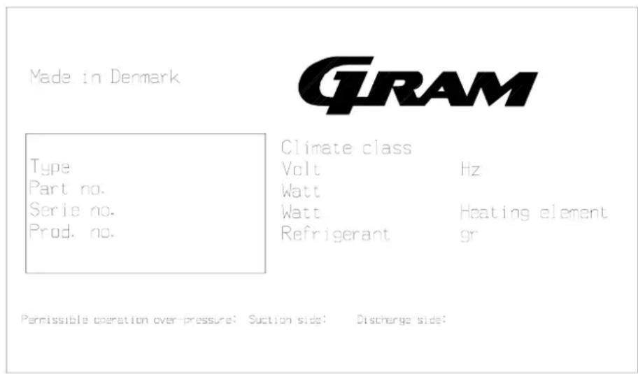
The refrigerating system and the hermetically sealed compressor require no maintenance - they merely have to be kept clean. The front grill under the door can be removed by pushing it upwards. If refrigeration fails, first look to see whether the cabinet has been unintentionally switched off, or whether a fuse has blown. If the cause of failure cannot be found, contact your supplier quoting TYPE, PART NO and SER.NO of the cabinet. This information can be found on the nameplate which is situated on the inside top right hand corner.
Disposal
If the cabinet is to be disposed of, please do so in an environmentally correct way. There are special requirements/conditions to be observed.
Nameplate
DEUTSCH
Aufstellen
EN FRANÇAIS
Mise en place
NEDERLANDS
SVENSKA
Uppställning
NORSK
Placement
SUOMI
Placement
Gram Commercial NUF
Gram Commercial
Spireaveien 6 Regementsgatan 52 c
0580 Oslo S-217 48 Malmö
Tel.: 22 88 17 50 Tel.: 40987848
Gram Deutschland GmbH. Gram Nederland B.V. Gram (UK) Ltd.
Holztorstrasse 60
Bornerbroeksestraat 147
2 The Technology Centre
31157 Sarstedt
7601 AP Almelo
London Road, Swanley
Tel.: 05066 - 60 46 - 0
Tel.: 546-454252
Kent BR 8 7AG
Tel.: 1322-616900

Gram Commercial A/S
6500 Vojens - Denmark
Tlf.: +45 73 20 12 00