
M250 - Loudspeaker BOSTON ACOUSTICS - Free user manual and instructions
Find the device manual for free M250 BOSTON ACOUSTICS in PDF.
| Product type | Column speaker |
| Brand | Boston Acoustics |
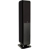
| Model | M250 |
| Frequency response | 62 Hz - 30 kHz (±3 dB) |
| Recommended amplifier power | 50 - 200 watts |
| Impedance | 8 ohms |
| Sensitivity | 86 dB (1 watt, 2.83 V at 1 m) |
| Crossover frequency | 3000 Hz |
| Tweeter | 1-inch (2.5 cm) EWB dome |
| Woofer | 5¼-inch (13.3 cm) polypropylene cone |
| Dimensions (H x W x D) | 97.6 x 24.5 x 25 cm |
| Weight | 16.0 kg |
| Enclosure type | Boston Lo-Q™ (minimizes interference) |
| Feet | Rubber feet and spikes included |
| Connection terminals | Gold-plated 5-way binding posts |
| Grille | Removable cloth grille |
| Power | Passive (powered by external amplifier) |
| Cleaning | Dry cloth only |
| Operating temperature | Dry indoor use |
| Included accessories | Rubber feet, spikes, bases |
Frequently Asked Questions - M250 BOSTON ACOUSTICS
User questions about M250 BOSTON ACOUSTICS
0 question about this device. Answer the ones you know or ask your own.
Ask a new question about this device
Download the instructions for your Loudspeaker in PDF format for free! Find your manual M250 - BOSTON ACOUSTICS and take your electronic device back in hand. On this page are published all the documents necessary for the use of your device. M250 by BOSTON ACOUSTICS.
USER MANUAL M250 BOSTON ACOUSTICS
IMPORTANT SAFETY INSTRUCTIONS

This symbol found on the apparatus indicates hazards arising from dangerous voltages.

This symbol found on the apparatus indicates the user should read all safety statements found in the user manual.

This symbol found on the apparatus indicates double insulation.

WARNING! To reduce the risk of fire or electrical shock, do not expose this apparatus to rain or moisture.
This symbol found on the apparatus indicates that the apparatus must be placed in a separate collection facility for electronic waste and not disposed with household waste.
-
Read these instructions.
-
Keep these instructions.
-
Heed all warnings.
-
Follow all instructions.
-
Do not use this apparatus near water.
-
Clean only with dry cloth.
-
Do not block any ventilation openings. Install in accordance with the manufacturer's instructions.
-
Do not install near any heat sources such as radiators, heat registers, stoves, or other apparatus (including amplifiers) that produce heat.
-
Do not defeat the safety purpose of the polarized or grounding type plug. A polarized plug has two blades with one wider than the other. A grounding-type plug has two blades and a third grounding prong. The wide blade or the third prong is provided for your safety. If the provided plug does not fit into your outlet, consult an electrician for replacement of the obsolete outlet.
-
Protect the power cord from being walked on or pinched particularly at plugs, convenience receptacles, and the point where they exit from the apparatus.
-
Only use attachments/accessories specified by the manufacturer.
-
Unplug this apparatus during lightning storms or when unused for long periods of time.
-
Refer all servicing to qualified service personnel. Servicing is required when the apparatus has been damaged in any way, such as power-supply cord or plug is damaged, liquid has been spilled or objects have fallen into the apparatus, the apparatus has been exposed to rain or moisture, does not operate normally, or has been dropped.
-
Maintain a minimum distance of 2^ (50mm) around the front, rear, and sides of the apparatus for sufficient ventilation. The ventilation should not be impeded by covering the ventilation openings or placing on or around the apparatus items such as newspapers, table-cloths, curtains, etc.
-
No open flame sources, such as lighted candles, should be placed on the apparatus.
-
The apparatus shall not be exposed to dripping or splashing. No objects filled with liquids, such as vases, shall be placed on the apparatus.
-
Either the power inlet connector on the rear of the apparatus or the power plug at the wall must remain accessible, to be able to disconnect power from the apparatus.
- To completely disconnect this apparatus from the AC Mains, disconnect the power supply cord plug from the AC receptacle.
- The mains plug of the power supply cord shall remain readily operable.

American Users:
Note: This equipment has been tested and found to comply with the limits for a Class B digital device, pursuant to part 15 of the FCC Rules. These limits are designed to provide reasonable protection against harmful interference in a residential installation. This equipment generates, uses, and can radiate radio frequency energy and, if not installed and used in accordance with the instructions, may cause harmful interference to radio communications. However, there is no guarantee that interference will not occur in a particular installation. If this equipment does cause harmful interference to radio or television reception, which can be determined by turning the equipment off and on, the user is encouraged to try to correct the interference by one or more of the following measures:
Reorient or relocate the receiving antenna.
- Increase the separation between the equipment and receiver.
- Connect the equipment into an outlet on a circuit different from that to which the receiver is connected.
- Consult the dealer or an experienced radio/TV technician for help.

Canadian Users
Use only with the cart, stand, tripod, bracket, or table specified by the manufacturer, or sold with the apparatus. When a cart is used, use caution when moving the cart/apparatus combination to avoid injury from tip-over.
Introduction
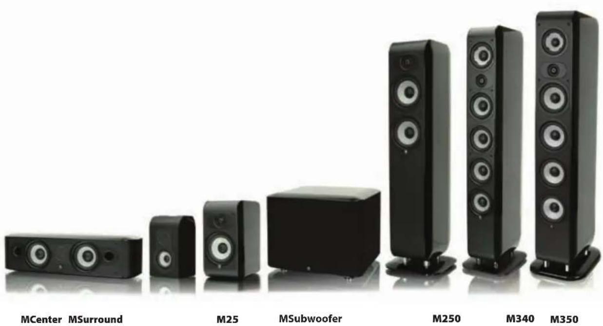
Thank you for selecting Boston Acoustics. The M Series family of loudspeakers is designed to deliver exceptionally accurate and natural sound reproduction from an aesthetically pleasing design. Each M Series model is specifically engineered to provide superior acoustic results for the intended application.
The M350, M340, M250 and M25 utilize the Extended Wide Bandwidth (EWB) tweeteter and Boston Lo-Q™ Cabinet construction for pure sound reproduction and minimal interference from the cabinet. The MCenter and MSurround utilize an innovative new Balanced Mode Radiator (BMR) high-frequency driver to provide even sound output over a remarkably wide area for clear dialog reproduction and an immersive surround-sound field for all listeners. The look of the M Series includes traditional and modern design cues that provide exceptional sonic results and allow them to easily integrate in a wide variety of home décor. All of the M Series models are designed to blend seamlessly with each other and to mix and match with other Boston Acoustics speakers providing great results regardless of the system configuration and speaker types. We hope that you enjoy your Boston Acoustics purchase for many years to come.
Features
- Second generation Extended Wide Bandwidth (EWB) Tweeter (M350, M340, M250 & M25) to minimize phase shift and distortion while improving pistonic motion
- Balanced Mode Radiator (BMR) high frequency diver (MCenter & MSurround) to maximize dispersion resulting in improved dialog intelligibly and surround-sound field immersion for all listeners
- Polypropylene midrange with mass loading (M350 & M340) provides smooth overall response with minimal coloration in the critical midrange frequencies
- Polypropylene woofers are lightweight and rigid with large motor structures for maximum low frequency output and heat dissipation
Boston Lo-QTM Cabinet Design (All except MSurround &MSubwoofer) to minimize cabinet response and interference - Leatherette covered baffle (All except MSubwoofer & MSurround in White)
- Rounded cabinet design with premium quality finish
Solid aluminum stand-offs (M350, M340 & M250) - 5-way gold-plated precision binding posts
High quality crossover network filter circuit boards and components
M340
M250
M25
Specifications M350
| Frequency Range (±3dB): | 45Hz - 30kHz 45Hz - 30kHz 60Hz - 30kHz 62Hz - 30kHz | |||
| High-Frequency Driver: | 1" (2.5cm) 1" (2.5cm) EWB Dome EWB Dome EWB Dome EWB Dome | |||
| Mid-Frequency Driver: | 4½" (11.4cm) 4½" (11.4cm) mass loaded polypropylene cone | 5¼" (13.3cm) mass loaded polypropylene cone | polypropylene cone mid/low driver | |
| Low-Frequency Driver(s): | 4 x 5¼" (13.3cm) polypropylene cones | 4 x 4½" (11.4cm) polypropylene cones | 5¼" (13.3cm) polypropylene cone | 5¼" (13.3cm) polypropylene cone |
| Crossover Frequency: | 400/3,000Hz | 390/3,100Hz | 450/2,900Hz | 3,000Hz |
| Impedance: | Compatible with 8 ohm outputs | Compatible with 8 ohm outputs | Compatible with 8 ohm outputs | Compatible with 8 ohm outputs |
| Sensitivity: [1 watt (2.83V) at 1m] | 90dB | 88dB | 88dB | 86dB |
| Recommended Amplifier Power | 50-500 watts | 50-350 watts | 50-250 watts | 50-200 watts |
| Dimensions (H x W x D): | 42³/8 x 9/8 x 12³/8" (107.6 x 24.5 x 31cm) | 40³/8 x 8¹³/16 x 11²/16" (102.6 x 22.4 x 29cm) | 38/16 x 9/8 x 9³/16" (97.6 x 24.5 x 25cm) | 12³/8 x 6⁵/16 x 10³/16" (31.4 x 17.6 x 25.8cm) |
| Weight: | 55.9 lbs (25.4kg) | 46.3 lbs (21.0kg) | 35.3 lbs (16.0kg) | 14.7 lbs (6.7kg) |
| Specifications MCenter | MSurround | MSubwoofer | ||
| Frequency Range (±3dB): | 68Hz - 22kHz 95Hz - 22kHz 23Hz - 150Hz | |||
| High-Frequency Driver: | 2½" (6.4cm) BMR flat panel | 2½" (6.4cm) BMR flat panel | — | |
| Low-Frequency Driver(s): | 2 x 4½" (11.4cm) polypropylene cones | 3½" (8.9cm) polypropylene cone | 10" (25.4cm) polypropylene cone 2 x 8" (20.3cm) polypropylene cone passive radiators | |
| Crossover Frequency: | 700Hz | 700Hz | 40Hz - 180Hz (variable) | |
| Impedance: | Compatible with 8 ohm outputs | Compatible with 8 ohm outputs | — | |
| Sensitivity: [1 watt (2.83V) at 1m] | 87dB | 86dB | — | |
| Amplifier Power: | — | — | 500 watts RMS (1000 watts Peak) | |
| Recommended Amplifier Power | 50-200 watts 50-150 watts | |||
| Dimensions (H x W x D): | 6/8 x 21/8 x 7/16" (15.5 x 55 x 18cm) | 9½ x 6/16" x 47/16" (24.2 x 16.6 x 11.3cm) | 13/16 x 16/4 x 15/16" (33.1 x 42.5 x 39.2cm) | |
| Weight: | 15.9 lbs (7.2kg) 5.5 lbs (2.5kg) | 51.8 lbs (23.5kg) | ||
Specifications subject to change without notice.
Unpacking the System
Carefully unpack the speakers. If there is any sign of damage from transit, report it immediately to your dealer or delivery service. Retain the shipping carton and packing materials for future use.
Grilles
The cloth grilles should remain on the speaker during normal use. However, to remove a grille, use your fingers to carefully pry the top edge of the grille away from the cabinet so you can insert your fingers between the grille and the cabinet. Then slide your fingers down the inside of the grille frame from top to bottom which will cause the grille to pop free. The grille is NOT designed to be removed by only pulling on one side. The pins that hold the grille can be damaged. Also, do not use any objects other than your fingers to remove the grille as the finish or grille may be damaged. Be careful to keep rings, watches and other sharp objects from scratching the finish or tearing the grille cloth.
To replace the grille, carefully align the two pins at the top of the grille with their corresponding grommets and gently push them in until the grille is supported by the grommets. Then work your way down the grille gently pushing the grille pins into the grommets evenly until the grille is fully seated. Be careful to align the pins with the grommets so the cabinet, grille pins and grommets are not damaged. Also, take care to support the speaker so it does not tip over or fall off its mounting location while the grille is being removed or replaced. MCenter Note: The same grille removal and replacement procedures apply to the MCenter except you will begin at the left or right side and work towards the opposite side. MSubwoofer Note: The MSubwoofer grille is not removable.
Feet & Spikes
The M350, M340 and M250 come with rubber feet installed at the factory which are ideal for hardwood floors. Spikes are also included for placement on a carpeted surface. To install the spikes, carefully lay the speaker on its back on a soft, debris-free surface and remove the rubber feet by hand turning them counter-clockwise. Thread the spikes by hand to make sure they are inserted properly. Save the rubber feet for future use.
The M25, MCenter, and MSurround come with rubber stand-offs that are designed to be attached to the bottom of the loudspeaker when stand, shelf or cabinet mounting. This will minimize the vibration transferred from the loudspeaker to the stand, shelf or cabinet. It will also help to protect the finish of the loudspeaker and the mounting location. The MSubwoofer comes with rubber feet installed at the factory.
MSurround Note: It is recommended to mount the rubber stand-offs on the back of the side panels of the MSurround if it is going to be wall mounted. This will minimize the amount of vibration that is transferred directly to the wall. You may need to adjust the depth of the mounting screws to help ensure that the speaker is not mounted too loosely or too tightly.
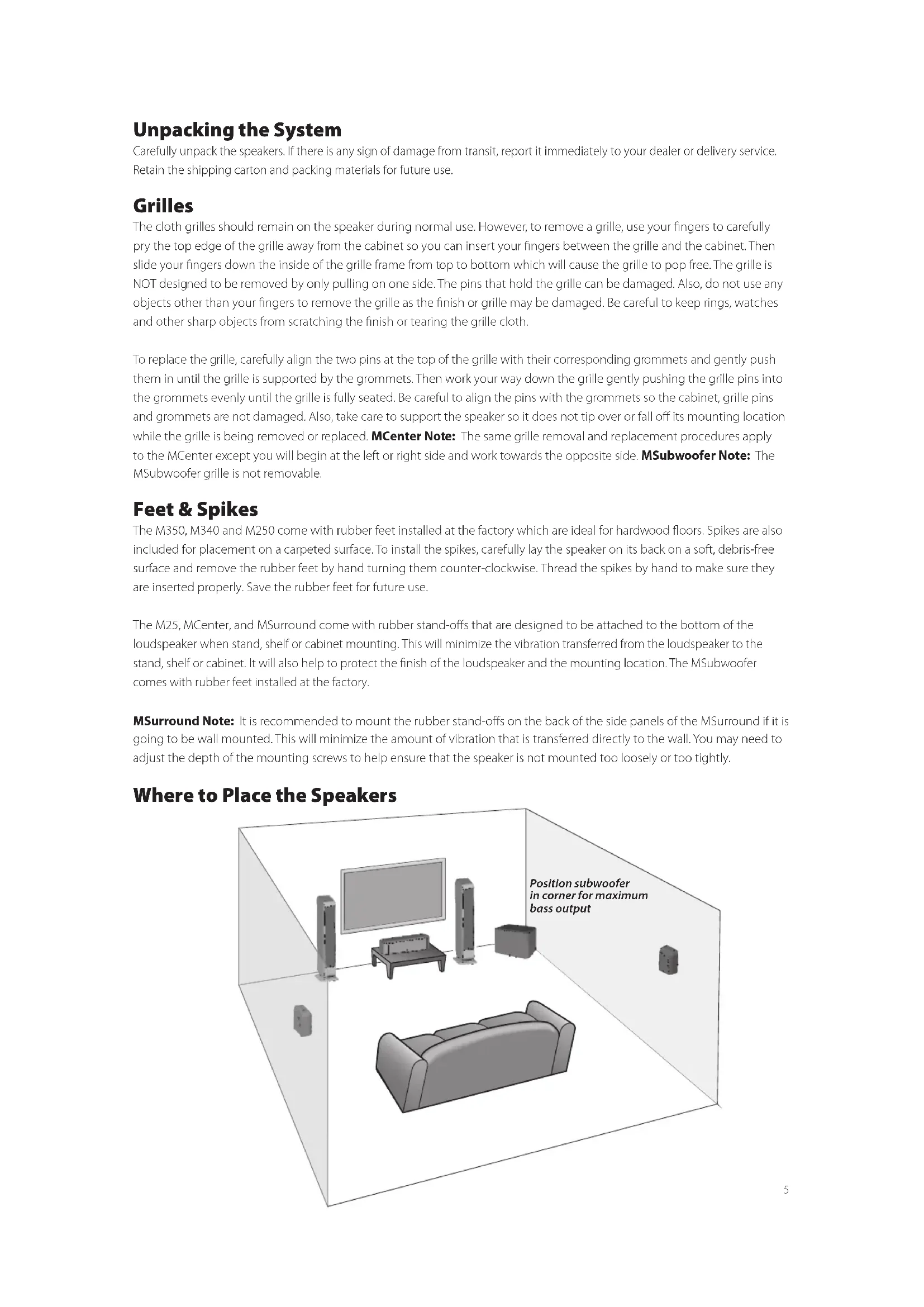
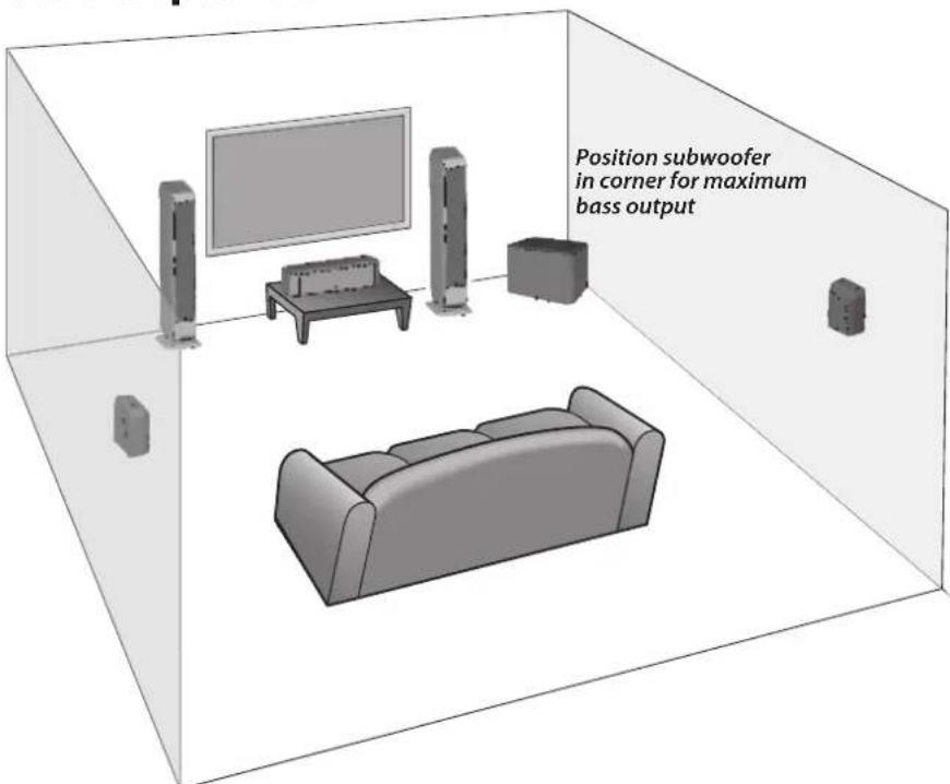
Where to Place the Speakers
Front Left and Right Speakers
For optimal results, it is advisable to start with the front left and right speakers positioned 6-12 feet (2-4m) apart from each other, at least 3 inches (76mm) away from the wall or curtains behind them, and at least 2 feet (0.6m) away from the corners of the room. Putting the front left and right speakers too close to a wall or corner can produce an unnatural bass reinforcement and side wall reflections that can detract from the speakers balanced, uncolored sound. If your listening position happens to be less than the distance the speakers are apart, then you may prefer to aim the front of the speakers' inward toward the primary listening position ("toe-in"). Experimentation is key to finding the best front left and right speaker positions. Playing a piece of stereo music that you are very familiar with and has a large range of frequencies is often the simplest way to find the best speaker locations for your room and listening preferences.
Center Speaker
For optimal results, it is advisable to place the center speaker directly below, behind (perforated screens only) or above the center of the screen. The BMR driver has extremely wide dispersion characteristics so it is not necessary to "aim" the center speaker baffle towards the listening position. If placed on a shelf or cabinet, position the speaker so the front of it is flush with the edge of the shelf or cabinet. This will avoid sound reflections that detract from the balanced, uncolored sound.
Surround Speakers
For optimal results, it is advisable to position the surround speakers directly to the side of the listening position, above ear level and at least 2 feet (0.6m) away from the corners of the room. If the speakers are mounted more than 3 inches (76mm) from the ceiling, it is advisable to position the speaker so the two ports are aimed towards the ceiling. If the speaker is mounted within 3 inches (76mm) of the ceiling, it is advisable to position the speaker so that the two ports are aimed towards the floor.
There are two 4-way hangers built into the back of the MSurround for wall mounting the loudspeaker vertically or horizontally with the ports pointing in either direction. It is recommended to mount the rubber stand-offs on the back of the side panels of the MSurround if it is going to be wall mounted. This will minimize the amount of vibration that is transferred directly to the wall. Consult a person knowledgeable about your wall type to recommend suitable hardware for hanging the speaker. Usually it is best to leave soundbar off the wall until connections are made.
Connections
After your speakers are properly placed, you are ready to wire your system.
Loudspeaker Connections
Before you connect the speakers turn off all the system components. The M Series loudspeakers feature gold-plated 5-way binding posts. They can accept bare wires, pin lugs, spade lugs, banana plugs or dual banana plugs.
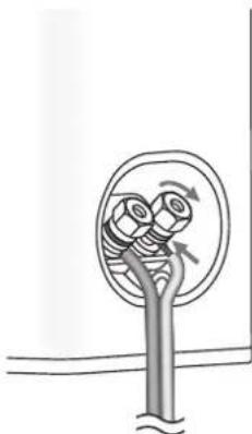
The illustration shows the bare wire speaker connection method. Remove about 38 (10mm) of the wire insulation. Twist the strands of the wire into a neat bundle. Loosen the top cap by turning it counter-clockwise until the hole in the center of the terminal post is fully accessible. Insert the wire through the hole and turn the top cap clockwise by hand to clamp it in place. Do not use tools to tighten it. Be sure that no strands of wire are able to make contact with the opposite terminal post. Repeat for the other loudspeaker connections.
If you are using pin lugs, attach them to the wires as specified by the manufacturer. Loosen the top cap by turning it counterclockwise until the hole in the center of the terminal post is fully accessible. Insert the pin lug through the hole and turn the top cap clockwise by hand to clamp it in place. Do not use tools to tighten it. Repeat for the other loudspeaker connections.
If you are using spade lugs, attach them to the wires as specified by the manufacturer. Loosen the top cap by turning it counter-clockwise until there is enough clearance for the spade lug to be positioned around the terminal post. Place the spade lug around the post and turn the top cap clockwise by hand to clamp it in place. Do not use tools to tighten it. Repeat for the other loudspeaker connections.
If you are using single or dual banana plugs, attach them to the wire as specified by the manufacturer. Turn the top cap of the terminal clockwise to ensure that it is fully seated. Do not use tools to tighten it. Insert the banana plug into the hole provided in the center of the top cap. Repeat for the other loudspeaker connections.
For information on connecting the speaker wires to your receiver or amplifier, refer to its owner's manual.
Important!
To ensure the best performance, observe polarities when making loudspeaker connections. The terminal cups have + and - symbols included on them and the top caps have a red ring for + and black ring for -. Connect each + terminal on the back of the amplifier or receiver to the respective + (red) terminal on each loudspeaker. Connect the - (black) terminals in the same way. If the connections are not made correctly, it can cause poor bass response and imaging. Also, to avoid short circuits that may damage your equipment, be careful not to let the ends of the wires to make contact with the ends of any other wires.
Subwoofer
For optimal results, place the subwoofer on the same wall (or in a corner) as your front speakers. In principal, the lower the crossover point, the greater the distance the subwoofer can be from the front speakers, however, the sound is typically best when the subwoofer is within 12 feet (3.5m) of the front speakers. The perceived level of bass output from the subwoofer will vary significantly at different positions in the room. When placed near walls, the output level is emphasized with corner placement providing the highest perceived output level. Placement away from walls may produce too little perceived bass. Regardless of the perceived bass level within the room, you always have the ability to adjust the level of the subwoofer from the built in volume control or from the level control of your preamplifier or receiver. If at any time you move the subwoofer, be sure to re-check your outputs levels and EQ settings if any. Since the human ear is less able to localize low frequencies, the bass will still appear to come from the front speakers. Experimentation is key but most positions in the room should work well.
IMPORTANT: Do not place the subwoofer where there is a chance of contact between the rear panel and drapes or furniture. The amplifier panel also serves to dissipate heat and should have at least 3 inches (76mm) clearance so it does not overheat.
NOTE: Power is always supplied to the MSubwoofer electronics unless it is unplugged or switched to the OFF position using the power switch located on the rear panel. The auto-on circuitry only activates or deactivates the power amplifier. Make sure your MSubwoofer and preamp/receiver are unplugged when making connections.
Power: When plugging in your MSubwoofer be sure to use a wall outlet, or dedicated electrical outlet. Some receivers will provide a switched outlet. Do not use this. These on board electrical outlets do not offer the amount of current or proper isolation required by a power amplifier, such as the one in your MSubwoofer.
Line level or LFE: On most systems use the Line Level input or the LFE input. These inputs accept the line-level signal from your preamp/receiver's subwoofer output. Your receiver's manual should indicate which input is most appropriate.
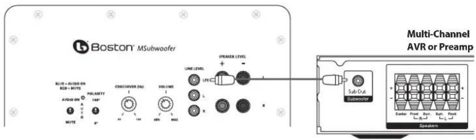
Connecting the Subwoofer to Digital Home Theater Systems Using LFE
Multi-channel home theater electronics dedicate one channel (the ".1") to reproduce the low-frequency effects (LFE) (such as explosions and thunder) contained in digitally-encoded soundtracks.
Hooked up this way, the receiver's amplifier is relieved of having to reproduce the difficult low bass signals that can drive the receiver into audible distortion. In some cases it can also depend on several other settings within a receiver. We recommend consulting your receiver manual for further assistance in this area.
Use an audio RCA cable (not included), as shown, to connect your digital receiver's LFE/subwoofer output to the subwoofer. Connect the other end to the Line Level/LFE input.
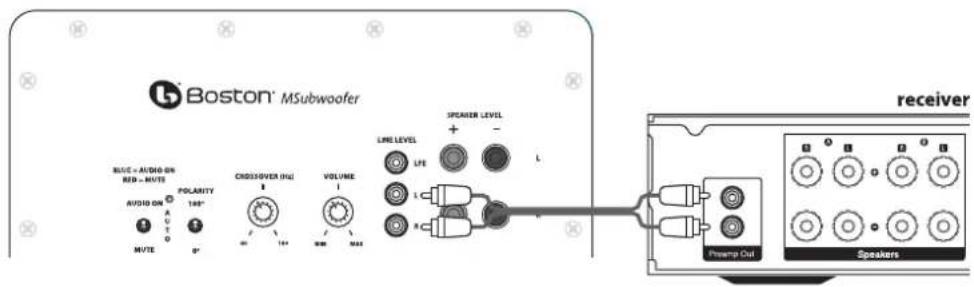
Connecting to Electronics Without a Subwoofer Output
If the preamp/receiver in your system does not have a subwoofer or LFE output you can connect the MSubwoofer to a preamp/variable output. Use a stereo audio RCA cable (not included) to connect the preamp outputs to the "L" and "R" Line Level inputs. Note: for preamps without multiple preamp outputs, splitters may be required.
Adjusting the Crossover Control
When using the Line Level inputs (not the LFE input) the subwoofer's built-in crossover is engaged. As a starting point, set the crossover control on the subwoofer about 10Hz higher than the lower limit of your main speakers' bass response. Fine-tune the crossover setting by ear for the smoothest blend with your main speakers. The best setting of the crossover control will depend on speaker placement and personal preference.
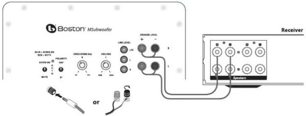
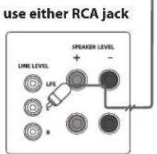
Speaker level
Use these high-level terminals with receivers that do not have subwoofer output. The speaker inputs accept both left and right channel speaker signals from your receiver. When using a home theater receiver, set the speaker type to "Large." The large setting will produce a fuller sound.
Note
Certain receivers use speaker grounding circuits that may be incompatible with external powered audio products, such as powered subwoofoers. When speaker wire is used instead of line level cables, this incompatibility can result in an audible hum when the receiver is turned off or switched to a different speaker channel.
If this should happen with your MSubwoofer,
you will need to make a ground cable and connect it to either RCA line input on the subwoofer and any unused RCA line input or output on your receiver (see diagram). The proper ground cable for this application should consist of two male RCA plugs that have their negative outside terminals (or "sleeve") connected to each other by any length of single conductor copper cable.
back of subwoofer
back of receiver
use any available RCA jack
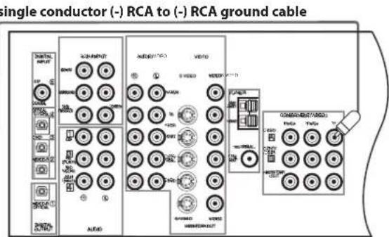
Note: The inside positive (or "pin") terminals should not be wired in either plug.
MSubwoofer Operation
Audio On/Auto/Mute
Plug the MSubwoofer's AC cord into a wall outlet. Do not use the outlets on the back of the receiver. Set the Audio On switch to the desired setting.
AUDIO ON - The MSubwoofer audio is always on.
AUTO - The MSubwoofer audio will turn on whenever a signal is detected. If no signal is detected after several minutes, it will automatically enter the Mute mode.
MUTE - The MSubwoofer is muted and will not produce any sound. You may want to unplug your MSubwoofer if you will not be using it for some time or wish to conserve electricity. You may also turn off the main power switch, located next to the power cord.
An LED indicator next to the Polarity switch indicates what mode the MSubwoofer is in.
OFF - The MSubwoofer is unplugged or power switch is in the "Off" position.
RED - Mute (No signal detected, Audio Off)
BLUE - Audio On (Signal detected, Audio On)
The MSubwoofer will automatically enter the Mute mode after several minutes when no signal is detected from your system. The MSubwoofer audio will then turn on when a signal is detected.
Polarity Control
(0^ or 180^) : Selects regular (0^) or inverted (180^) phase for the MSubwoofer. Set this switch to provide the fullest, most dynamic bass. The effect of phase will be most audible on low-frequency percussion instruments or music with a continuously repeating bass line.
Crossover Control
Adjusts the frequency of the low pass filter for the MSubwoofer. Note: This control is not active when using the LFE input jack.
Volume Control
Turn the MSubwoofer Volume control to the 11 o'clock position. If no sound emanates from the MSubwoofer check the AC-line cord, Audio On switch, Power switch, and input cables.
Adjust the MSubwoofer Volume control until you hear a match between the main speaker and MSubwoofer. Bass response should not overpower the room but rather be adjusted so there is a natural blend across the entire musical range.
Maintenance and Service
All wiring connections should be inspected and cleaned at least once a year.
If a problem does occur, make sure that all connections are properly made, secure and clean. If a problem occurs in one loudspeaker, rewire that speaker in a different location within the system. Should the problem persist then the problem is with the speaker. If the speaker works fine in the new position it is a strong indication of an issue with the wiring or electronics in the system. In the event that your speakers ever need service, contact your Boston Acoustics dealer or visit bostonacoustics.com.
Limited Warranty
Boston Acoustics warrants to the original purchaser of an M Series Loudspeaker that it will be free of defects in materials and workmanship in its mechanical parts for a period of 5 years from the date of purchase. The warranty period for the electrical components of the MSubwoofer is 1 year.
Your responsibilities are to install and use them according to the instructions supplied, to provide safe and secure transportation to an authorized Boston Acoustics service representative, and to present proof of purchase in the form of your sales slip when requesting service.
Excluded from this warranty is damage that results from abuse, misuse, improper installation, accidents, shipping, or repairs/modifications by anyone other than an authorized Boston Acoustics service representative.
This warranty is limited to the Boston Acoustics product and does not cover damage to any associated equipment. This warranty does not cover the cost of removal or reinstallation. This warranty is void if the serial number has been removed or defaced. This warranty gives you specific legal rights, and you may also have other rights which vary from state to state.
If Service Seems Necessary
First, contact the dealer from whom you purchased the product.
Or contact us via e-mail at:
US: support@bostona.com
Japan: ba_info@dm-holdings.com
Asia Pacific: service@dm-singapore.com
If that is not possible, write to:
Boston Acoustics, Inc.
100 Corporate Drive
Mahwah, NJ 07430 U.S.A.
We will promptly advise you of what action to take. If it is necessary to return your subwoofer, please ship it prepaid to the above address. After it has been repaired, we will return it freight prepaid in the United States and Canada.
For EU Customers Only
This symbol found on the product indicates that the product must not be disposed of with household waste.
Instead, it may be placed in a separate collection facility for electronic waste or returned to a retailer when
purchasing similar product. The producer paid to recycle this product. Doing this contributes to reuse and recycling,
minimizes adverse effects on the environment and human health and avoids any fines for incorrect disposal.
Japon: ba_info@dm-holdings.com
En Asia Pacifico: service@dm-singapore.com
Boston Acoustics, Inc.
100 Corporate Drive
BLUE - Audio active (signal detected, Audio active)
Japon: ba_info@dm-holdings.com
Asie-Pacifique:service 品 dm-singapore.com
Boston Acoustics, Inc.
100 Corporate Drive
Asia Pacifico: service@dm-singapore.com
Boston Acoustics, Inc.
100 Corporate Drive
Mahwah, NJ 07430 U.S.A.
Japan: ba_info@dm-holdings.com
Asien Stilla havet: service@dm-singapore.com
Boston Acoustics, Inc.
100 Corporate Drive
Mahwah, NJ 07430 U.S.A.
Japan: ba_info@dm-holdings.com
Boston Acoustics, Inc.
100 Corporate Drive
Mahwah, NJ 07430 U.S.A.
Use only with the cart, stand, tripod, bracket, or table specified by the manufacturer, or sold with the apparatus. When a cart is used, use caution when moving the cart/apparatus combination to avoid injury from tip-over.
n安全注意事项

注意触电危险,请勿打开。

注意:
Boston Acoustics, Inc.
100 Corporate Drive
Mahwah, NJ 07430 U.S.A.
This symbol found on the product indicates that the product must not be disposed of with household waste. Instead, it may be placed in a separate collection facility for electronic waste or returned to a retailer when purchasing similar product. The producer paid to recycle this product. Doing this contributes to reuse and recycling, minimizes adverse effects on the environment and human health and avoids any fines for incorrect disposal.

- IMPORTANT SAFETY INSTRUCTIONS
- American Users:
- Canadian Users
- Introduction
- Features
- Unpacking the System
- Grilles
- Feet & Spikes
- Where to Place the Speakers
- Front Left and Right Speakers
- Center Speaker
- Surround Speakers
- Connections
- Loudspeaker Connections
- Important!
- Subwoofer
- Connecting the Subwoofer to Digital Home Theater Systems Using LFE
- Connecting to Electronics Without a Subwoofer Output
- Adjusting the Crossover Control
- Speaker level
- Note
- MSubwoofer Operation
- Audio On/Auto/Mute
- Polarity Control
- Crossover Control
- Volume Control
- Maintenance and Service
- Limited Warranty
- If Service Seems Necessary
- For EU Customers Only
- n安全注意事项
Brand : BOSTON ACOUSTICS
Model : M250
Category : Loudspeaker